Table of Contents
Advertisement
Quick Links
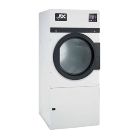
AD-285DH / AD-285D
Installation Manual
Phase 7 / Dual Timer / S.A.F.E. System
! ! ! ! !
WARNING:
FIRE OR EXPLOSION HAZARD
Failure to follow safety warnings exactly
could result in serious injury, death or
property damage.
– Do not store or use gasoline or other
flammable vapors and liquids in the
vicinity of this or any other appliance.
– WHAT TO DO IF YOU SMELL GAS
● ● ● ● ●
Do not try to light any appliances.
● ● ● ● ●
Do not touch any electrical switch;
do not use any phone in your
building.
● ● ● ● ●
Clear the room, building or area of
all occupants.
● ● ● ● ●
Immediately call your gas supplier
from a neighbor's phone. Follow
the gas supplier's instructions.
● ● ● ● ●
If you cannot reach your gas
supplier, call the fire department.
– Installation and service must be
performed by a qualified installer, service
agency or the gas supplier.
! ! ! ! !
AVERTISSEMENT:
RISQUE D'INCENDIE OU D'EXPLOSION
Le non-respect des avertissements de
sécurité pourrait entraîner des blessures
graves, la mort ou des dommages
matériels.
– N'entreposer pas et n'utilisez pas
d'essence ni d'autres vapeurs ou
liquides inflammables dans le voisinage
de cet appareil ou de tout autre appareil.
– QUE FAIRE SI VOUS SENTEZ UNE
ODEUR DE GAZ
● ● ● ● ●
Ne tentez pas d'allumer d'appareil.
● ● ● ● ●
Ne touchez à aucun interrupteur. Ne
vous servez pas des téléphones se
trouvant dans le bâtiment où vous
vous trouvez.
● ● ● ● ●
Évacuez la pièce, le bâtiment ou la zone.
● ● ● ● ●
Appelez immédiatement votre
fournisseur de gaz depuis un voisin.
Suivez les instructions du fournisseur.
● ● ● ● ●
Si vous ne pouvez rejoindre le
fournisseur de gaz, appelez le service
des incendies.
– L'installation et l'entretien doivent être
assurés par un installateur ou un service
d'entretien qualifié ou par le fournisseur
de gaz.
American Dryer Corporation
88 Currant Road, Fall River MA 02720-4781 USA
Telephone: +1 (269) 923-3000 / Fax: +1 (508) 678-9447
e-mail: mdl-service@whirlpool.com / www.adclaundry.com
ADC Part No. 113235- 17
Advertisement
Table of Contents

Related Manuals for American Dryer Corp. AD-285DH


Summary of Contents for American Dryer Corp. AD-285DH
- Page 1 AD-285DH / AD-285D Installation Manual Phase 7 / Dual Timer / S.A.F.E. System ! ! ! ! ! ! ! ! ! ! WARNING: AVERTISSEMENT: FIRE OR EXPLOSION HAZARD RISQUE D’INCENDIE OU D’EXPLOSION Failure to follow safety warnings exactly Le non-respect des avertissements de could result in serious injury, death or sécurité...
- Page 2 Retain This Manual In A Safe Place For Future Reference American Dryer Corporation products embody advanced concepts in engineering, design, and safety. If this product is properly maintained, it will provide many years of efficient, trouble free, and most importantly, safe operation. ONLY qualified technicians should service this equipment.
- Page 3 In the State of Massachusetts, the following installation instructions apply: ■ Installations and repairs must be performed by a qualified or licensed contractor, plumber, or gas fitter qualified or licensed by the State of Massachusetts. ■ Acceptable Shut-off Devices: Gas Cocks and Ball Valves installed for use shall be listed.
- Page 4 WARNING UNDER NO CIRCUMSTANCES should the dryer door switches, lint drawer switch, or heat safety circuit ever be disabled. WARNING DO NOT MODIFY THIS APPLIANCE. WARNING The dryer must never be operated with any of the back guards, outer tops, or service panels removed.
-
Page 5: Table Of Contents
Table of Contents SECTION I SAFETY PRECAUTIONS ....................3 SECTION II SPECIFICATIONS ......................6 SECTION III INSTALLATION PROCEDURES .................. 9 A. Unpacking/Setting Up ......................... 9 B. Location Requirements ........................10 C. Dryer Enclosure Requirements ......................11 D. Fresh Air Supply Requirements ......................12 E. - Page 6 SECTION VII DATA LABEL INFORMATION ..................37 SECTION VIII PROCEDURE FOR FUNCTIONAL CHECK OF REPLACEMENT COMPONENTS ............... 38 SECTION IX SENSOR ACTIVATED FIRE EXTINGUISHING (S.A.F.E.) SYSTEM ....41 SECTION X PROGRAMMING ......................47 A. Non-Coin Programming ........................47 B. Coin Programming ..........................48...
-
Page 7: Safety Precautions
SECTION I SAFETY PRECAUTIONS WARNING: For your safety, the information in this manual must be followed to minimize the risk of fire or explosion or to prevent property damage, personal injury, or loss of life. WARNING: The dryer must never be operated with any of the back guards, outer tops, or service panels removed. - Page 8 WARNING: DO NOT dry mop heads. Contamination by wax or flammable solvents will create a fire hazard. WARNING: DO NOT use heat for drying articles that contain plastic, foam, sponge rubber, or similarly textured rubberlike materials. Drying in a heated tumbler may damage plastics or rubber and may be a fire hazard.
- Page 9 IMPORTANT: Dryer must be installed in a location/environment, which the ambient temperature remains between 40° F (4.44° C) and 130° F (54.44° C). CE ONLY IMPORTANT: This appliance must only be installed and operated in the country of destination indicated on the dryer’s data plate. If the appliance is to be installed and operated in a country other than the one indicated on the data plate, a data plate amendment must be obtained from American Dryer Corporation.
-
Page 10: Specifications
SECTION II SPECIFICATIONS MODEL ADG-285DH (WITH HEAT RECLAIMER) MODEL ADG-285D (NO HEAT RECLAIMER) 13.6 kg MAXIMUM CAPACITY (DRY WEIGHT) 30 lb TUMBLER DIAMETER 27-1/4” 69.22 cm TUMBLER DEPTH 30” 76.2 cm 288.27 L TUMBLER VOLUME 10.18 cu ft 0.373 kW TUMBLER/DRIVE MOTOR 1/2”... - Page 11 ADG-285DH (with Heat Reclaimer) Specifications NOTE: ADC reserves the right to make changes in specifications at any time without notice or obligation. 113235 - 17 www.adclaundry.com...
- Page 12 ADG-285D (No Heat Reclaimer) Specifications NOTE: ADC reserves the right to make changes in specifications at any time without notice or obligation. American Dryer Corp. 113235 - 17...
-
Page 13: Installation Procedures
SECTION III INSTALLATION PROCEDURES Installation should be performed by competent professional in accordance with local, state, and country codes. In the absence of these codes, the installation must conform to applicable American National Standards: National Fuel Gas Code ANSI Z223.1/NFPA 54 and National Electric Code ANSI/NFPA 70, or in Canada, the installation must conform to applicable Canadian Standards: Natural Gas and Propane Installation Code CSA B149.1 and Canadian Electric Code CSA C22.1. -
Page 14: Location Requirements
B. LOCATION REQUIREMENTS Before installing the dryer, ensure the location conforms to local codes and ordinances. In the absence of such codes or ordinances the location must conform with National Fuel Gas Code ANSI Z223.1/NFPA 54, or in Canada, the installation must conform to applicable Canadian Standards: Natural Gas and Propane Installation Code CSA B149.1. -
Page 15: Dryer Enclosure Requirements
C. DRYER ENCLOSURE REQUIREMENTS Bulkheads and partitions should be made of noncombustible materials and must be located a minimum of 12-inches (30.48 cm) above the dryer’s outer top; except along the front of the dryer, which may be closed if desired. -
Page 16: Fresh Air Supply Requirements
D. FRESH AIR SUPPLY REQUIREMENTS This appliance may only be installed in a room that meets the appropriate ventilation requirements specified in the national installation regulations. When the dryer is operating, it draws in room air, heats it, passes this air through the tumbler, and exhausts it out of the building. -
Page 17: Exhaust Requirements
E. EXHAUST REQUIREMENTS Exhaust ductwork should be designed and installed by a qualified professional. Improperly sized ductwork will create excessive back pressure, which results in slow drying, increased use of energy, and shutdown of the burner by the airflow (sail) switch, burner hi-limit, or lint chamber hi-heat protector thermostat. The dryer must be installed with a proper exhaust duct connection to the outside. - Page 18 IMPORTANT: DO NOT use screens, louvers, or caps on the outside opening of the exhaust ductwork. NOTE: As per the National Fuel Gas Code, “Exhaust ducts for type 2 clothes dryers shall be constructed of sheet metal or other noncombustible material. Such ducts shall be equivalent in strength and corrosion resistance to ducts made of galvanized sheet steel not less than 26 gauge (0.0195-inches [0.50 mm]) thick.”...
- Page 19 HORIZONTAL VENTING OF MODEL ADG-285D (No Heat Reclaimer) When horizontal single 8-inch (20.32 cm) venting is used with model ADG-285D, the ductwork to the outlet cannot exceed 40 feet (12 meters) refer to Illus. A2 below. This calculation of 40 feet (12 meters) compensates or allows for the use of a maximum of three (3) elbows in addition to that shown.
- Page 20 VERTICAL VENTING OF MODEL ADG-285DH (With Heat Reclaimer) When vertical single venting is used with model ADG-285DH, the minimum duct size is 8-inches (20.32 cm), refer to Illus. B1 below, the ductwork from the dryer to the outside outlet cannot exceed 60 feet (18 meters), refer to Illus.
- Page 21 If the length of the duct run or quantity of elbows used exceeds the above noted specifications, the cross section area of the ductwork must be increased in proportion to the number of elbows or duct run added. IMPORTANT: For extended ductwork runs, the cross section area of the duct can only be increased to an extent.
- Page 22 NOTE: Distance between dryer single ducts being connected to the main common duct must be a minimum of 28-1/2” (72.39 cm) dryer width. Ductwork should be laid out in such a manner where allowances are made at rear area of the dryer for removal of rear service panels or guards.
-
Page 23: Electrical Information
Illus. D (refer to the illustration on the previous page) shows the minimum cross section area for vertical multiple dryer venting. These figures must be increased in proportion if the main duct run from the last dryer to where it exhausts has numerous elbows or is unusually long. IMPORTANT: For extended ductwork runs, the cross section area of the duct can only be increased to an extent. - Page 24 NOTE: ADC reserves the right to make changes in specifications at any time without notice or obligation. 2. Electrical Service Specifications IMPORTANT: Figures shown are for non-reversing models only. For reversing models contact the factory. ELECTRICAL SERVICE SPECIFICATIONS (PER DRYER) IMPORTANT: 208 VAC AND 230/240 VAC ARE NOT THE SAME.
- Page 25 4. Electrical Connections A wiring diagram is located inside the control box for connection data. If local codes permit, power to the dryer can be made by the use of a flexible U.L. listed power cord/pigtail (wire size must conform to rating of dryer), or the dryer can be hard wired directly to the service breaker panel.
- Page 26 Single-Phase Electrical Lead Connections White or Red Black Green Neutral Positive Ground or L2 FOR 110V APPLICATIONS FOR 208-240V APPLICATIONS A ground lug is provided in the rear electrical box to connect your service ground. American Dryer Corp. 113235 - 17...
-
Page 27: Gas Information
G. GAS INFORMATION It is your responsibility to have ALL plumbing connections, materials, and workmanship conform to local and state regulations or codes of the country of destination. In the absence of such codes, ALL plumbing connections, materials, and workmanship must conform to the applicable local requirements. In the USA this is National Fuel Gas Code ANSI Z223.1/NFPA 54, or in Canada, Natural Gas and Propane Installation Code CSA B149.1. - Page 28 2. Technical Gas Data a. Gas Specifications For Australia, refer to data plate. TYPE OF GAS NATURAL PROPANE Manifold Pressure* 3.5 inches W.C. 8.7 mb 10.5 inches W.C. 26.1 mb In-Line Pressure 6.0 - 12.0 inches W.C. 14.92 - 29.9 mb 11.0 inches W.C.
- Page 29 Installer within Australia – refer to AS/NZS5601.1 for guidance on gas supply pipe sizing required for this appliance installation. The dryer is provided with a 1/2” N.P.T. inlet pipe connection located in the upper rear of the dryer. The minimum pipe size (supply line) to the dryer is 1/2” pipe. For ease in servicing, the gas supply line of each dryer must have its own shutoff valve.
- Page 30 Consistent gas pressure is essential at ALL gas connections. It is recommended that a 3/4-inch (19.05 mm) pipe gas loop be installed in the supply line servicing a bank of dryers. An in-line pressure regulator must be installed in the gas supply line (header) if the (natural) gas pressure exceeds 12.0 inches (29.9 mb) of water column (W.C.) pressure.
-
Page 31: Preparation For Operation And Start-Up
H. PREPARATION FOR OPERATION AND START-UP The following items should be checked before attempting to operate the dryer: 1. Read ALL “CAUTION,” “WARNING,” and “DIRECTION” labels attached to the dryer. 2. Check incoming supply voltage to be sure that it is the same as indicated on the dryer data label. 3. -
Page 32: Preoperational Test
I. PREOPERATIONAL TEST ALL dryers are thoroughly tested and inspected before leaving the factory. However, a preoperational test should be performed before the dryer is publicly used. It is possible that adjustments have changed in transit or due to marginal location (installation) conditions. Installer must instruct the user on how to correctly operate the dryer before leaving. -
Page 33: Preoperational Instructions
NOTE: If computer program changes are required, refer to the computer programming section of the manual supplied with the dryer. 5. The dryer should be operated through one (1) complete cycle to ensure that no further adjustments are necessary and that ALL components are functioning properly. TUMBLER COATING The tumbler is treated with a protective coating. - Page 34 2. Mechanical Drop/Rotary Coin Meter or Slide Coin Meter a. Insert coin and turn knob (rotary type meter), or for slide meter unit, push in coin chute. b. Select Temperature. c. Push the “Start” button. d. To stop dryer, open the main door. NON-COIN MODELS 1.
-
Page 35: Shutdown Instructions
DUAL TIMER DRYERS 1. Turn drying timer knob for a time of 20 minutes. 2. Select “High Temp.” 3. Push “Push to Start” button. 4. To stop dryer, open the main door. Spin and dwell (stop) times are adjustable at the reversing timer. -
Page 36: Service And Parts Information
SECTION IV SERVICE AND PARTS INFORMATION A. SERVICE Only properly licensed or trained technicians should service the dryer. If service is required, contact the reseller from whom the ADC equipment was purchased. If the reseller cannot be contacted or is unknown, contact the ADC Service Department for a reseller in your area. -
Page 37: Warranty Information
SECTION V WARRANTY INFORMATION A. WARRANTY REGISTRATION Warranty registration for this product is done on-line. To do so, go to www.adclaundry.com. First choose SERVICE (top left), then WARRANTY, then WARRANTY REGISTRATION. This registration is intended to serve the customer wherein, we record the individual installation date and warranty information to better serve you should you file a warranty claim. - Page 38 2. Each part must be tagged with the following information: a. Model number and serial number of the dryer from which part was removed. b. Nature of failure (be specific). c. Date of dryer installation. d. Date of part failure. e.
-
Page 39: Routine Maintenance
SECTION VI ROUTINE MAINTENANCE A. CLEANING A program and/or schedule should be established for periodic inspection, cleaning, and removal of lint from various areas of the dryer, as well as throughout the ductwork system. The frequency of cleaning can best be determined from experience at each location. -
Page 40: Adjustments
90 DAYS Inspect and remove lint accumulation in customer furnished exhaust ductwork system from dryer’s internal exhaust ducting. WARNING: THE ACCUMULATION OF LINT IN THE EXHAUST DUCTWORK CAN CREATE A POTENTIAL FIRE HAZARD. WARNING: DO NOT OBSTRUCT THE FLOW OF COMBUSTION AND VENTILATION AIR. -
Page 41: Data Label Information
SECTION VII DATA LABEL INFORMATION STANDARD LABEL CE LABEL When contacting American Dryer Corporation, certain information is required to ensure proper service/parts AGA LABEL information from ADC. This information is on the data label that is affixed to either the backside of the upper control door or left side panel/wall area behind the control door. -
Page 42: Procedure For Functional Check Of Replacement Components
SECTION VIII PROCEDURE FOR FUNCTIONAL CHECK OF REPLACEMENT COMPONENTS 1. Microprocessor Controller (Computer) Board a. Phase 7 Coin Models 1) Upon completing installation of the replacement microprocessor controller (computer) board, reestablish power to the dryer. 2) Start the drying cycle by pressing any temperature selection keys (HI, MED, or LO). 3) Verify that the applicable indicator lights on the microprocessor controller (computer) board are lit. - Page 43 b. Phase 7 Non-Coin Models 1) Upon completing installation of the replacement microprocessor controller (computer) board, reestablish power to the dryer. 2) Start the drying cycle by pressing any of the preset cycles in letters A-F. 3) Verify that the applicable indicator lights on the microprocessor controller (computer) board are lit.
- Page 44 2. For Models with Direct Spark Ignition (DSI) Module (Type I) Theory of Operation: Start the drying cycle. When the gas burner ignites within the chosen trial for ignition time (6-seconds), the flame sensor detects gas burner flame and signals the DSI module to keep the gas valve open as long as there is a call for heat.
-
Page 45: Sensor Activated Fire Extinguishing (S.a.f.e.) System
SECTION IX SENSOR ACTIVATED FIRE EXTINGUISHING (S.A.F.E.) SYSTEM The exclusive Sensor Activated Fire Extinguishing (S.A.F.E.) System will extinguish fires that may start in the drying tumbler. A series of sensors positioned throughout the tumbler and interfaced with the microprocessor will trigger the S.A.F.E. system water jet(s) to quickly extinguish the flames. The water jet(s) remain on for 2 minutes and will automatically activate again if a fire condition remains or reignites. - Page 46 WARNING: If the water in the supply line or water solenoid valve freezes, the S.A.F.E. system will be INOPERATIVE!! IMPORTANT: Appliance is to be connected to the water mains using a new hose set and the old hose set should not be reused. 2.
- Page 47 OPTIONAL MANUAL BYPASS Provisions are made in the dryer S.A.F.E. system for the installation of an optional manual bypass. Depending on the model dryer, the connections for the manual bypass are made at the “T” or “three way” fitting located in the outlet supply side of the water solenoid valve.
- Page 48 3. Electrical Requirements No independent external power source or supply connection is necessary. The 24 volt power to operate the S.A.F.E. system is accomplished internally in the dryer (from the dryer controls). WARNING: Electrical power must be provided to the dryer at ALL times. If the main electrical power supply to the dryer is disconnected, the S.A.F.E.
- Page 49 S.A.F.E. SYSTEM WATER VALVE CHECK The operation of the water solenoid valve can be tested to ensure that the water supply system and valve are functional. Before attempting a system check, be sure that ALL water supply shutoff valves to the dryer are in the OPEN position;...
- Page 50 S.A.F.E. SYSTEM DIAGNOSTICS MESSAGES OPEN THERMISTOR PROBE – This message indicates that the S.A.F.E. system thermistor probe either is not connected or is damaged. If this condition is detected, the Phase 7 non-coin control will immediately enter S.A.F.E. SYSTEM DISABLED mode. SHORTED THERMISTOR PROBE –...
-
Page 51: Programming
SECTION X PROGRAMMING SAIL SWITCH OPEN FAULT – Sail switch remained open after A. NON-COIN PROGRAMMING the cycle started. Should have closed. BURNER HIGH LIMIT FAULT – Burner temp. disk has opened. BURNER IGNITION CONTROL – No signal to gas valve from (DSI) module during trial for ignition time. -
Page 52: Coin Programming
Accessing and Clearing Coin Vault Total B. COIN PROGRAMMING Enter program mode by switching program switch (up) while no Enter the programming mode by placing the switch on the Phase 7 cycle is in progress. board in the up position while no cycle is in progress. “Program Press HI –... - Page 53 NOTES ____________________________________________________________________________________________________________________ ___________________________________________________________________________________________________________________________ ___________________________________________________________________________________________________________________________ ___________________________________________________________________________________________________________________________ ___________________________________________________________________________________________________________________________ ___________________________________________________________________________________________________________________________ ___________________________________________________________________________________________________________________________ ___________________________________________________________________________________________________________________________ ___________________________________________________________________________________________________________________________ ___________________________________________________________________________________________________________________________ ___________________________________________________________________________________________________________________________ ___________________________________________________________________________________________________________________________ ___________________________________________________________________________________________________________________________ ___________________________________________________________________________________________________________________________ ___________________________________________________________________________________________________________________________ ___________________________________________________________________________________________________________________________ ___________________________________________________________________________________________________________________________ ___________________________________________________________________________________________________________________________ ___________________________________________________________________________________________________________________________ ___________________________________________________________________________________________________________________________ ___________________________________________________________________________________________________________________________ ___________________________________________________________________________________________________________________________ ___________________________________________________________________________________________________________________________ ___________________________________________________________________________________________________________________________ 113235 - 17 www.adclaundry.com...
- Page 54 ADC Part No. 113235 17 - 06/07/22...
Need help?
Do you have a question about the AD-285DH and is the answer not in the manual?
Questions and answers