Table of Contents
Advertisement
Quick Links
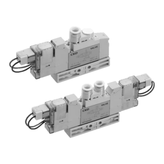
3, 5-PORT PNEUMATIC SOLENOID VALVE
(M)3GA/B R SERIES
(M)4GA/B R SERIES
(M)3GD/E R SERIES
(M)4GD/E R SERIES
・Single Valve
・Manifold (Metal Base)
INSTRUCTION MANUAL
SM-P00077-A/3
INSTRUCTION MANUAL
SM-358642
• Read this Instruction Manual before using the product.
• Read the safety notes carefully.
• Keep this Instruction Manual in a safe and convenient place for future reference.
Advertisement
Table of Contents

Subscribe to Our Youtube Channel
Related Manuals for CKD M3GA/B R Series


Summary of Contents for CKD M3GA/B R Series
- Page 1 3, 5-PORT PNEUMATIC SOLENOID VALVE (M)3GA/B R SERIES (M)4GA/B R SERIES (M)3GD/E R SERIES (M)4GD/E R SERIES ・Single Valve ・Manifold (Metal Base) INSTRUCTION MANUAL SM-P00077-A/3 INSTRUCTION MANUAL SM-358642 • Read this Instruction Manual before using the product. • Read the safety notes carefully. •...
-
Page 2: Preface
• Since there are a wide variety of customer applications, it is impossible for CKD to be aware of all of them. Depending on the application or usage, the product may not be able to exercise its full performance or an accident may occur due to fluid, piping, or other conditions. -
Page 3: Safety Information
SM-P00077-A/3 SAFETY INFORMATION SAFETY INFORMATION When designing and manufacturing any device incorporating the product, the manufacturer has an obligation to ensure that the device is safe. To that end, make sure that the safety of the machine mechanism of the device, the pneumatic or water control circuit, and the electric system that controls such mechanism is ensured. -
Page 4: Precautions On Product Use
• For applications where life or properties may be adversely affected and special safety measures are required. (Exception is made if the customer consults with CKD prior to use and understands the specifications of the product. However, even in that case, safety measures must be taken to avoid danger in case of a possible failure.) -
Page 5: Table Of Contents
SM-P00077-A/3 CONTENTS CONTENTS PREFACE ........................... i SAFETY INFORMATION ....................ii Precautions on Product Use ..................iii CONTENTS ........................iv PRODUCT OVERVIEW ..................... 1 Part Name ......................1 Model Number Indication ..................5 1.2.1 Single valve ....................5 1.2.2 Manifold ......................8 1.2.3 Related products .................. -
Page 6: Contents
SM-P00077-A/3 CONTENTS 3.1.6 Pressure sensor (option symbol: G1, G2) ............ 64 Manual Operation ..................... 67 3.2.1 Non-locking/locking combination manual override ........67 3.2.2 Residual pressure exahust mechanism (option symbol: X, X1) ....68 MAINTENANCE AND INSPECTION ............... 69 Periodic Inspection.................... 69 Disassembling and Assembling ................ -
Page 7: Product Overview
SM-P00077-A/3 1. PRODUCT OVERVIEW 1. PRODUCT OVERVIEW 1.1 Part Name Base piping type single valve Body piping type single valve Mounting plate Individual wiring manifold Reduced wiring manifold (figure shown is DIN rail mount) Common terminal block (T10) Common terminal block (T11) D-sub connector (T30) M3 thread fastening type Clamping type... - Page 8 SM-P00077-A/3 1. PRODUCT OVERVIEW Flat cable connector (T51) Flat cable connector (T50) Serial transmission (T6) Serial transmission (T8) DIN terminal box (B) Socket with cover (EJ) Pressure sensor (G1) Pressure sensor (G2) Residual pressure exhaust mechanism (X, X1) 2020-04-15...
- Page 9 SM-P00077-A/3 1. PRODUCT OVERVIEW Part name Description Lead wire Wire which has no polarity. Cover provided with a power indicator on the top surface which lights green while the Electrical component cover coil is energized (only for E-type and A-type connectors). Coil assembly which varies depending on the type of electrical connection and voltage Coil assembly selected for the valve.
- Page 10 Connector provided with a set of terminals for controlling the manifold valves. Serial transmission slave unit Slave unit specifically designed for manifold manufactured by CKD. Terminal box provided with a power indicator which lights green while the coil is DIN terminal box energized.
-
Page 11: Model Number Indication
SM-P00077-A/3 1. PRODUCT OVERVIEW 1.2 Model Number Indication 1.2.1 Single valve ● Single valve ( e ) ( a ) ( b ) ( c ) ( d ) ( f ) ( g ) ( h ) ● Single valve for mounting on base ( e ) ( a ) ( b ) - Page 12 SM-P00077-A/3 1. PRODUCT OVERVIEW Note 1: (e) Port size Symbol Description Variation Ports 4(A), 2(B) Ports P, R1, R2 ø1.8 barbed fitting ø1.8 push-in fitting ø4 push-in fitting M5, Rc1/8 ø6 push-in fitting M5, Rc1/8, Rc1/4 ø8 push-in fitting Rc1/8, Rc1/4 ø10 push-in fitting Rc1/4 Rc1/8...
- Page 13 SM-P00077-A/3 1. PRODUCT OVERVIEW Note 3: (g) Option Symbol Description Blank Non-locking/locking combination manual override Non-locking type manual override Equipped with exhaust malfunction prevention valves Mounting plate External pilot Ozone/cutting oil proof Surgeless Low heat generating/energy saving circuit Built-in A/B-port filter 1-port detection type pressure sensor (pressure range: 0 MPa to 0.7 MPa) 2-port detection type pressure sensor (pressure range: 0 MPa to 0.7 MPa) Non-locking type residual pressure exhaust mechanism...
-
Page 14: Manifold
SM-P00077-A/3 1. PRODUCT OVERVIEW 1.2.2 Manifold ●Manifold model no. ●Single valve for mounting on base (a) Number of ports (b) Piping direction (c) Series (d) Solenoid position (e) Port size Symbol Description Symbol Description Symbol Description Symbol Description Note 4 3-port valve (two M4G1R 2-position... - Page 15 SM-P00077-A/3 1. PRODUCT OVERVIEW Note 4: (e) Port size Symbol Description Variation Ports 4(A), 2(B) Ports P, R1, R2 ø1.8 barbed fitting Rc1/8 ø1.8 push-in fitting Rc1/8 ø4 push-in fitting Rc1/8, Rc1/4 ø6 push-in fitting Rc1/8, Rc1/4, Rc3/8 ø8 push-in fitting Rc1/8, Rc1/4, Rc3/8 ø10 push-in fitting Rc1/4, Rc3/8...
- Page 16 SM-P00077-A/3 1. PRODUCT OVERVIEW Note 5: (f) Electrical connection Individual wiring Symbol Description Lead wire, DIN terminal box Blank Grommet lead wire (300 mm) DIN terminal box (Pg7) With surge suppressor/lamp DIN terminal box (Pg7) (without terminal box) With surge suppressor E-type connector (top and side socket entries) Lead wire (300 mm) Lead wire (500 mm)
- Page 17 SM-P00077-A/3 1. PRODUCT OVERVIEW Reduced wiring Symbol Description Common terminal block (M3 thread) Left side connection T10R Right side connection Common terminal block (clamping) Left side connection T11R Right side connection D-sub connector Left side connection T30R Right side connection 20-pin flat cable connector Left side connection T50R...
- Page 18 SM-P00077-A/3 1. PRODUCT OVERVIEW Note 6: (h) Option Symbol Description Blank Non-locking/locking combination manual override Non-locking type manual override Equipped with exhaust malfunction prevention valves External pilot Ozone/cutting oil proof Surgeless Low heat generating/energy saving circuit Built-in A/B-port filter 1-port detection type pressure sensor (pressure range: 0 MPa to 0.7 MPa) 2-port detection type pressure sensor (pressure range: 0 MPa to 0.7 MPa) Non-locking type residual pressure exhaust mechanism Locking type residual pressure exhaust mechanism...
-
Page 19: Related Products
SM-P00077-A/3 1. PRODUCT OVERVIEW 1.2.3 Related products ◼ Mounting rail <N4GR-BAA> • Minimum length is 87.5 mm. • Select the length in pitches of 12.5 mm. ◼ Silencer <SLM-M5> <SLW-6S, 8S> Port size Cross section A-A Model Port size R1/8 13.3 10.5 10.5... -
Page 20: Kit Parts
SM-P00077-A/3 1. PRODUCT OVERVIEW 1.2.4 Kit parts ◼ Coil assembly Part name Model number 4GR-Electrical connection-Option-COIL-Rated voltage 1: 100 VAC 2: 200 VAC 3: 24 VDC 4: 12 VDC Coil assembly Blank: Standard (for individual wiring) A: Ozone-proof Blank: Grommet lead wire E□: E-type connector E□J: EJ-type connector B: DIN terminal box... - Page 21 SM-P00077-A/3 1. PRODUCT OVERVIEW ◼ Cartridge type fitting Model Part name Model number ø1.8 barbed 4G1R-JOINT-CF ø1.8 straight 4G1R-JOINT-C18 ø4 straight 4G1R-JOINT-C4 ø6 straight 4G1R-JOINT-C6 ø8 straight 4G1R-JOINT-C8 ø1.8 elbow 4G1R-JOINT-CL18, CLL18 4G1 R ø4 elbow 4G1R-JOINT-CL4, CLL4 ø6 elbow 4G1R-JOINT-CL6, CLL6 ø1/8 inch straight 4G1R-JOINT-C3N...
- Page 22 SM-P00077-A/3 1. PRODUCT OVERVIEW ◼ Plate kit Model Model number Kit contents 3GB1 R, 4GB1 R 4G1R-PLATE-KIT Plate (1), gasket (1), mounting screw (2) 3GB2 R, 4GB2 R 4G2R-PLATE-KIT Plate (1), gasket (1), mounting screw (2) 4GB3 R 4G3R-PLATE-KIT Plate (1), gasket (1), mounting screw (2) ◼...
- Page 23 SM-P00077-A/3 1. PRODUCT OVERVIEW ◼ DIN rail Model number Kit contents Mounting Manifold length Rail length pitch Longer than N4GR-BAA [*1] DIN rail (1) 47.5 or shorter 87.5 47.5 87.5 [*1] Specify the length to cut the DIN rail. 72.5 112.5 Select the rail length from the table to the right.
- Page 24 SM-P00077-A/3 1. PRODUCT OVERVIEW ◼ Gasket with exhaust malfunction prevention valve Model Model number 3G1 R, 4G1 R 4G1R-CHECK-VALVE 3G2 R, 4G2 R 4G2R-CHECK-VALVE 3G3 R, 4G3 R 4G3R-CHECK-VALVE ◼ PR check valve kit (2 per set) Model Model number 3G1 R, 4G1 R 4G1R-PR 3G2 R, 4G2 R...
- Page 25 SM-P00077-A/3 1. PRODUCT OVERVIEW ◼ Socket assembly for adding a valve For the socket assembly for adding a valve, specify a cable of appropriate length depending on the position where the valve is added. Incorrect selection may cause the cable to become disconnected or pinched. For A-type connector socket assembly, the position where the valve is added is indicated by specifying the row number, which is counted from the side on which the electrical component is mounted.
-
Page 26: Specifications
SM-P00077-A/3 1. PRODUCT OVERVIEW 1.3 Specifications 1.3.1 Common specifications Model 4G1 R, 4G2 R, 4G3 R Valve type and operation Pilot-operated soft spool valve Working fluid Compressed air Max. working pressure Note 3 Min. working pressure Proof pressure 1.05 Ambient temperature °C -5 to 55 (no freezing) Fluid temperature... -
Page 27: Response Times
SM-P00077-A/3 1. PRODUCT OVERVIEW 1.3.3 Response times (Unit: ms) 4GA/B R Series 4GD/E R Series 4GA/B1 R 4GA/B2 R 4GA/B3 R 4GD/E1 R 4GD/E2 R 4GD/E3 R Solenoid position Two 3-port valves integrated type Single 2-position Double 3-position connection * Values determined with surge suppressor/lamp are shown. They are values determined with a supply pressure of 0.5 MPa, a temperature of 20°C, and no lubrication. - Page 28 SM-P00077-A/3 1. PRODUCT OVERVIEW ◼ Manifold 1(P) -> 4(A)/2(B) 4(A)/2(B) -> 5(R1)/3(R2) Model Solenoid position C [dm /(s/bar)] C [dm /(s/bar)] Two 3-port valves integrated type 0.86 0.31 1.1 (0.66) 0.19 (0.22) M3GA1 R 2-position 0.99 0.20 1.2 (0.70) 0.20 (0.12) M4GA1 R All ports closed 0.94...
-
Page 29: Weight
SM-P00077-A/3 1. PRODUCT OVERVIEW 1.3.5 Weight ◼ 4GA/B R Series (Unit: g) Solenoid position/ 3GB1 R 3GB2 R 3GA1 R 3GA2 R 3GA3 R 4GA1 R 4GA2 R 4GA3 R 4GB3 R electrical connection 4GB1 R 4GB2 R Grommet lead wire (41) (74) (100) - Page 30 SM-P00077-A/3 1. PRODUCT OVERVIEW ◼ Manifold base • Body piping (Unit: g) M3GA1 R, M4GA1 R M3GA2 R, M4GA2 R M3GA3 R, M4GA3 R M3GD1 R, M4GD1 R M3GD2 R, M4GD2 R M3GD3 R, M4GD3 R Pilot air exhaust method Direct DIN rail Direct...
-
Page 31: Internal Structure
SM-P00077-A/3 1. PRODUCT OVERVIEW 1.4 Internal Structure 1.4.1 Description of operation ◼ Valve operation Diagram of operation (with 4GA R Series as an example) Description of operation De-energized (shown in the diagram) 1(P) -> 2(B) 4G□10R 4(A) -> 5(R1) 2-position Single Energized 1(P) ->... - Page 32 SM-P00077-A/3 1. PRODUCT OVERVIEW Diagram of operation (with 3GA R Series as an example) Description of operation De-energized (shown in the diagram) 3GA□10R 4(A) -> 5(R1) Normally closed Energized 1(P) -> 4(A) De-energized (shown in the diagram) 3GA□110R 1(P) -> 2(B) Normally open Energized 2(B) ->...
- Page 33 SM-P00077-A/3 1. PRODUCT OVERVIEW ◼ Manifold operation The main and pilot exhaust air are collected in the manifold base and discharged from the exhaust port. ◼ Malfunction prevention PR check valves are provided as a standard. PR check valves prevent malfunction of the solenoid valve itself caused by pilot back pressure. In addition, gaskets equipped with exhaust malfunction prevention valves can be selected as an option.
-
Page 34: Installation
• If cutting oil splashes onto the cylinder rod, the oil may enter into the secondary side piping of the solenoid valve through the cylinder, causing a malfunction. Consult CKD before using the product in such an environment. -
Page 35: Unpacking
SM-P00077-A/3 2. INSTALLATION 2.2 Unpacking CAUTION Do not remove the solenoid valves from their packaging bag until just before piping. If bags are opened before the valves are ready to be piped, foreign matters may enter inside the solenoid valves from the piping ports and may cause a failure or malfunction. •... -
Page 36: How To Mount A Body Piping Type Single Valve
SM-P00077-A/3 2. INSTALLATION 2.3.1 How to mount a body piping type single valve ◼ Mounting directly The 4GA2 R/4GA3 R Series body piping type single valve can be mounted using through holes or screw holes. When using screw holes, the recommended tightening torque is 0.7 N·m to 1.2 N·m (4GA1 R Series has only through holes). - Page 37 SM-P00077-A/3 2. INSTALLATION ◼ Mounting with mounting plate The way the body piping type single valve is mounted on the mounting plate differs among 2-position single, 2-position double, and 3-position. Attach the valve and the mounting plate in the right direction and use correct holes since damage can occur if not mounted correctly.
- Page 38 SM-P00077-A/3 2. INSTALLATION <For DIN terminal box and E-type connector (AC voltage) connections> 4GA1 R, 4GD1 R Series 2-position single 2-position double 3-position 4GA2 R, 4GD2 R Series 2-position single 2-position double 3-position 4GA3 R, 4GD3 R Series 2-position single 2-position double 3-position 2020-04-15...
-
Page 39: How To Mount A Base Piping Type Single Valve
SM-P00077-A/3 2. INSTALLATION 2.3.2 How to mount a base piping type single valve The base piping type single valve can be mounted using through holes in the subbase. 4GB1 R, 4GE1 R Series 4GB2 R, 4GE2 R Series 2-ø3.2 Mounting hole 2-ø4.4 Mounting hole 4GB3 R, 4GE3 R Series 2-ø4.3 Mounting hole... -
Page 40: How To Mount A Manifold
SM-P00077-A/3 2. INSTALLATION 2.3.3 How to mount a manifold ◼ Mounting with DIN rail The manifold can be mounted on the DIN rail by selecting a DIN rail mount manifold (mount type symbol: D) or by modifying a direct mount manifold with the DIN rail kit. If not mounted correctly, the manifold may fall off or become damaged. - Page 41 SM-P00077-A/3 2. INSTALLATION ◼ Mounting directly M4G2 R/M4G3 R Series can be mounted using through holes or screw holes. When using screw holes, select bolts that can be screwed in by at least 10 threads and tighten them with proper tightening torque. The recommended tightening torque is 1.0 N·m to 1.5 N·m (M4G1 R Series has only through holes).
-
Page 42: Piping
SM-P00077-A/3 2. INSTALLATION 2.4 Piping CAUTION Tighten the pipes/tubes with the appropriate tightening torque. Observe the appropriate tightening torque to prevent air leakage and damage to the threads. To prevent damage to the screw threads, first use your hands to lightly tighten the pipe/tube and then use a tool to tighten the pipe/tube further. -
Page 43: Seal Material
2.4.7 Piping connection ◼ Appropriate tube For solenoid valves provided with push-in fitting, use tubes specified by CKD. • Soft nylon tubes (F-1500 Series) • Urethane tubes (U-9500 Series) * For ø1.8 push-in fitting (C18), use UP-9402 (urethane). - Page 44 The tension applied sideways through the tube should not exceed 40 N (or 5 N for C18, CL18, and CLL18). ◼ Blanking plug to use For solenoid valves provided with push-in fitting, use blanking plugs specified by CKD: • Blanking plug (PG-P2-B) : ø1.8 push-in fitting •...
-
Page 45: Piping Ports For External Pilot (Option Symbol: K)
SM-P00077-A/3 2. INSTALLATION 2.4.8 Piping ports for external pilot (option symbol: K) The external pilot model (option symbol: K) has a separate pilot air exhaust. Since pilot air supply and exhaust ports are both M5 screw ports, make sure to pipe to correct ports. Otherwise, a malfunction may result. -
Page 46: Wiring
SM-P00077-A/3 2. INSTALLATION 2.5 Wiring WARNING Turn off the power before wiring. An electric shock may occur. Do not touch live parts with bare hands. An electric shock may occur. Thoroughly read and understand this Instruction Manual before working on electrical wiring. The product must be handled by a person who understands the structure and operation principle of solenoid valve and has knowledge to secure the safety. -
Page 47: E-Type Connector
SM-P00077-A/3 2. INSTALLATION 2.5.1 E-type connector E-type connector has entries on both the top and side to which a socket can be connected from either direction. The socket is attached to the side entry at shipment. Change the connecting direction depending on the installation environment. -
Page 48: Ej-Type ("Socket With Cover" Type) Connector
SM-P00077-A/3 2. INSTALLATION 2.5.3 EJ-type ("socket with cover" type) connector Do not bend the lead wire beyond the dimension shown below. 2.5.4 DIN terminal box ◼ Disassembling the DIN terminal box Loosen screw (1) and pull cover (2) in the direction of screw (1) to remove the connector from coil assembly (12). - Page 49 SM-P00077-A/3 2. INSTALLATION ◼ Wiring How to prepare for wiring: Applicable dimension for cable (7) is VCTF 2-conductor (3-conductor) (ø3.5 to ø7) defined in JIS C 3306. Length of sheath peeled from lead wires of cable is 10 mm. Either twisted wire or solid wire can be used for (11) wiring.
-
Page 50: Common Terminal Block (T10/T11)
SM-P00077-A/3 2. INSTALLATION 2.5.5 Common terminal block (T10/T11) ◼ Precautions on wiring the common terminal block (T10/T11) • With the common terminal block, common wires are connected beforehand. Therefore, use the same manifold power. When using an independent contact PLC output unit, wire so that contacts share a common connection. - Page 51 SM-P00077-A/3 2. INSTALLATION ◼ Examples of terminal layouts for wiring method T10 Maximum number of stations on the manifold varies depending on the model. Check individual specifications. In the table below, each valve number (Valve no.) consists of a number (the station number) and an alphabet (a for the a-side solenoid and b for the b-side solenoid).
- Page 52 SM-P00077-A/3 2. INSTALLATION ◼ Examples of terminal layouts for wiring method T11 Maximum number of stations on the manifold varies depending on the model. Check individual specifications. In the table below, each valve number (Valve no.) consists of a number (the station number) and an alphabet (a for the a-side solenoid and b for the b-side solenoid).
-
Page 53: D-Sub Connector (T30)
SM-P00077-A/3 2. INSTALLATION 2.5.6 D-sub connector (T30) ◼ Connector for T30 The connector used for wiring method T30, generally called D-sub connector, is used widely for FA and OA devices. The 25-pin D-sub connector is specified in the RS-232C standard and is especially used for communication between computers and peripheral devices. - Page 54 SM-P00077-A/3 2. INSTALLATION ◼ Examples of connector pin layouts for wiring method T30 Maximum number of stations on the manifold varies depending on the model. Check individual specifications. In the table below, each valve number (Valve no.) consists of a number (the station number) and an alphabet (a for the a-side solenoid and b for the b-side solenoid).
- Page 55 SM-P00077-A/3 2. INSTALLATION ◼ How to connect to PLC The common wiring has already been connected on the manifold side. Since the solenoid valves have no polarity, they can be connected to DC output unit (for PLC) of either output types (NPN or PNP). Wire according to the following diagrams.
- Page 56 SM-P00077-A/3 2. INSTALLATION ◼ CKD cable specifications CKD cables can be ordered using the following model numbers. 4GR-CABLE-D User-side end of cable Cable length Unfinished (cut to length only) With round terminal for M3.5 screw 4GR-CABLE-D00-*2 Multi-conductor cable (UL2464-SB-13P24AWG) D-sub connector: HDBB-25S from Hirose Electric Co., Ltd.
-
Page 57: Flat Cable Connector (T50)
SM-P00077-A/3 2. INSTALLATION 2.5.7 Flat cable connector (T50) ◼ Flat cable connector The connector used for wiring method T50 complies with MIL-C-83503 standard. Flat cable insulation displacement connector simplifies wiring work. Pin numbers are assigned differently depending on the PLC manufacturer, but the functions are assigned in the same way. - Page 58 SM-P00077-A/3 2. INSTALLATION ◼ Examples of connector pin layouts for wiring method T50 Maximum number of stations on the manifold varies depending on the model. Check individual specifications. In the table below, each valve number (Valve no.) consists of a number (the station number) and an alphabet (a for the a-side solenoid and b for the b-side solenoid).
- Page 59 SM-P00077-A/3 2. INSTALLATION ◼ Power supply This terminal block is used when power needs to be supplied from the external source. Supply power to the wiring block or the input/output unit in a manner as shown in the following figures. When properly connected, the power indicator will light up.
-
Page 60: Flat Cable Connector (T51/T52/T53)
SM-P00077-A/3 2. INSTALLATION 2.5.8 Flat cable connector (T51/T52/T53) ◼ Precautions on wiring the flat cable connector (T51/T52/T53) • Signal arrays of the PLC output unit must match signal arrays on the valve side. • Only 24 VDC or 12 VDC power can be used. •... - Page 61 SM-P00077-A/3 2. INSTALLATION ◼ Examples of connector pin layouts for wiring method T51 Maximum number of stations on the manifold varies depending on the model. Check individual specifications. In the table below, each valve number (Valve no.) consists of a number (the station number) and an alphabet (a for the a-side solenoid and b for the b-side solenoid).
- Page 62 SM-P00077-A/3 2. INSTALLATION ◼ Examples of connector pin layouts for wiring method T52 Maximum number of stations on the manifold varies depending on the model. Check individual specifications. In the table below, each valve number (Valve no.) consists of a number (the station number) and an alphabet (a for the a-side solenoid and b for the b-side solenoid).
- Page 63 SM-P00077-A/3 2. INSTALLATION ◼ Examples of connector pin layouts for wiring method T53 Maximum number of stations on the manifold varies depending on the model. Check individual specifications. In the table below, each valve number (Valve no.) consists of a number (the station number) and an alphabet (a for the a-side solenoid and b for the b-side solenoid).
- Page 64 SM-P00077-A/3 2. INSTALLATION ◼ How to connect to PLC The common wiring has already been connected on the manifold side. Since the solenoid valves have no polarity, they can be connected to DC output unit (for PLC) of either output types (NPN or PNP). Wire according to the following diagrams.
- Page 65 SM-P00077-A/3 2. INSTALLATION <For T53> Part name Model Manufacturer XG4M-2630 Socket XG4T-2604 Strain relief XG5M-2632-N Discrete-wire press connector Omron Corporation XG5M-2635-N Discrete-wire press connector XG5N-261-U Discrete-wire crimp connector (socket) XG5W-0231, 0232 Discrete-wire crimp connector (contact) ◼ Cable This system, in general, uses flat cables or thin multi-conductor cables. These cables have thin conductors and must be checked that they have sufficient mechanical strength and electrical capacity for the application.
-
Page 66: Usage
SM-P00077-A/3 3. USAGE 3. USAGE WARNING Consult CKD about the specifications before using the product outside the designated specifications or for special applications. 3.1 Safety Instructions 3.1.1 Air quality WARNING Do not supply anything other than compressed air. Use clean compressed air that does not contain corrosive gases. - Page 67 SM-P00077-A/3 3. USAGE ◼ Contamination • Use compressed air that does not contain oxidized oil, tar, carbon, or other contaminants from the air compressor. If oxidized oil, tar, or carbon enters into and adheres to pneumatic components, the resistance of the sliding section may increase and result in operation faults.
-
Page 68: Electric Circuit
SM-P00077-A/3 3. USAGE 3.1.2 Electric circuit CAUTION Check for leakage currents from external control devices to prevent a malfunction. When a programmable controller or a similar control device is used, a leakage current may prevent the valve from operating correctly even if the solenoid valve is de-energized. When controlling solenoid valves using a programmable controller or a similar control device, make sure that the leakage current from the programmable controller output is as specified in the table below. -
Page 69: Surgeless (Option Symbol: S)
SM-P00077-A/3 3. USAGE 3.1.3 Surgeless (option symbol: S) Diodes are incorporated in the solenoid valves of surgeless models to reduce the surge voltage of solenoid valves to approximately 1 V. There is no polarity with 4G R Series. Voltage V Approx. -
Page 70: Pressure Sensor (Option Symbol: G1, G2)
SM-P00077-A/3 3. USAGE 3.1.6 Pressure sensor (option symbol: G1, G2) DANGER Do not diassemble or dismantle the pressure sensor. Parts can fly off when pressure is applied. Use the product within the specified voltage range. Applying voltage beyond the specified range may cause a malfunction, damage to the product, electric shock, or fire. - Page 71 SM-P00077-A/3 3. USAGE ◼ Pressure sensor specifications Working pressure 0 MPa to 0.7 MPa Characterstic between analog output voltage and pressure Supply voltage 10.8 VDC to 30.0 VDC Current consumption 5 mA (24 VDC, at no load) Pressure detection method Diffused semiconductor pressure switch Ambient temperature 0°C to 55°C...
- Page 72 SM-P00077-A/3 3. USAGE ◼ How to replace the pressure sensor <1-port detection type (option symbol: G1)> Pressure sensor Insert the connecting part of the sensor all the way into the connection port. Pull on the sensor to check that it does not come off.
-
Page 73: Manual Operation
SM-P00077-A/3 3. USAGE 3.2 Manual Operation WARNING After operating the manual override (including the residual pressure exhaust mechanism), return the cylinder to the original position (initial position) before re-starting operation. Make sure that nobody is near the cylinder to be activated before performing manual operation (including residual pressure exhaust). -
Page 74: Residual Pressure Exahust Mechanism (Option Symbol: X, X1)
SM-P00077-A/3 3. USAGE 3.2.2 Residual pressure exahust mechanism (option symbol: X, X1) ◼ How to open and close the cover Do not apply excessive force to the cover when opening and closing the cover. Excessive external force may cause damage (below 5 N). Cover ◼... -
Page 75: Maintenance And Inspection
SM-P00077-A/3 4. MAINTENANCE AND INSPECTION 4. MAINTENANCE AND INSPECTION 4.1 Periodic Inspection WARNING Turn off the power, stop the supply of compressed air, and make sure that there is no residual pressure before maintenance. Observe the condition to ensure safety. CAUTION Plan and perform daily and periodic inspections so that maintenance can be managed properly. -
Page 76: Disassembling And Assembling
SM-P00077-A/3 4. MAINTENANCE AND INSPECTION 4.2 Disassembling and Assembling WARNING Thoroughly read and understand this Instruction Manual before working on disassembly or assembly of the manifold. • The product must be handled by a person who understands the structure and operation principle of solenoid valve and has knowledge to secure the safety. -
Page 77: How To Replace A Cartridge Type Fitting (4Ga/B R, 4Gd/E R)
SM-P00077-A/3 4. MAINTENANCE AND INSPECTION 4.2.3 How to replace a cartridge type fitting (4GA/B R, 4GD/E R) To change the push-in fitting size, check the procedure before replacing. If it is not installed correctly or if the tightening of the mounting screws is insufficient, problems such as air leakage will occur. ◼... - Page 78 SM-P00077-A/3 4. MAINTENANCE AND INSPECTION ◼ Base piping (4GB R/4GE R) type Remove the mounting screws. Pull out the fitting stopper plate and fitting at the same time. Adjust the groove on the replacement fitting to the fitting stopper plate and assemble them temporarily.
-
Page 79: How To Change Piping Connection Specifications (4Ga/B R)
SM-P00077-A/3 4. MAINTENANCE AND INSPECTION 4.2.4 How to change piping connection specifications (4GA/B R) Observe the tightening torque of the mounting screws when replacing the plate or the fitting adaptors attached to the body, when changing the body piping specifications and base piping specifications, or when changing the push-in fitting and internal thread specifications of body piping type. -
Page 80: Adding A Valve To The Reduced Wiring Manifold
SM-P00077-A/3 4. MAINTENANCE AND INSPECTION 4.3 Adding a Valve to the Reduced Wiring Manifold WARNING Turn off the power and release the pressure before adding a manifold valve. 4.3.1 How to add to the position where spare wiring is equipped The masking plate at the reserved adding location is equipped with spare wiring beforehand. -
Page 81: How To Open And Close The Reduced Wiring Cover
SM-P00077-A/3 4. MAINTENANCE AND INSPECTION 4.3.3 How to open and close the reduced wiring cover ◼ How to open the reduced wiring cover Open the reduced wiring cover by hooking the tip of a precision screw driver to the cable through hole on the cover. -
Page 82: Instructions For Wiring The Electric Circuit Board Connectors
SM-P00077-A/3 4. MAINTENANCE AND INSPECTION 4.3.4 Instructions for wiring the electric circuit board connectors Rules for establishing correspondence between the connectors on the electric circuit board and the valves differ depending on the wiring specifications. When wiring the electric circuit board connectors, always check the connector numbers printed on the circuit board. - Page 83 SM-P00077-A/3 4. MAINTENANCE AND INSPECTION Wire in the order indicated by the arrows. Electric circuit board assembly Correspondence between connectors and valves 1) Single solenoid valves only (maximum of 16 stations) Connector no. Valve no. Connector no. Valve no. 2) Double solenoid valves only (maximum of 8 stations) Connector no.
- Page 84 SM-P00077-A/3 4. MAINTENANCE AND INSPECTION Wire in the order indicated by the arrows. Electric circuit board assembly Correspondence between connectors and valves 1) Single solenoid valves only (maximum of 20 stations) Connector no. Valve no. Empty Empty Connector no. Valve no. Empty Empty 2) Double solenoid valves only (maximum of 12 stations)
-
Page 85: Troubleshooting
Keep organic chemicals away. Port A or B is open to atmosphere. Inspect and correct the piping. Foreign matters are stuck in packing. Remove foreign matters. If you have any other questions or concerns, contact your nearest CKD sales office or distributor. 2020-04-15... -
Page 86: Reference Information
SM-P00077-A/3 6. REFERENCE INFORMATION 6. REFERENCE INFORMATION 6.1 Port Identification Piping ports are identified and labeled, such as 1P and 4A, in accordance with ISO and JIS standards. Port ISO standard JIS standard Supply port Output port Output port Exhaust port Exhaust port Pilot air supply port 12/14... -
Page 87: Warranty Provisions
If the product specified herein fails for reasons attributable to CKD within the warranty period specified below, CKD will promptly provide a replacement for the faulty product or a part thereof or repair the faulty product at one of CKD’s facilities free of charge.
Need help?
Do you have a question about the M3GA/B R Series and is the answer not in the manual?
Questions and answers