Table of Contents
Advertisement
Quick Links
●
Please read this instruction manual carefully before using this product,
especially the section describing safety.
●
Retain this instruction manual with the product for further consultation
whenever necessary.
Discontinue
INSTRUCTION MANUAL
PILOT TYPE 3,5 PORTS
ELECTRIC-MAGNETIC
VALVE
(M)3GD/E1-SERIES
(M)3GD/E2-SERIES
(M)3GD3-SERIES
(M)4GD/E1-SERIES
(M)4GD/E2-SERIES
(M)4GD/E3-SERIES
Individual sub base type
Manifold type
SM-P00046-A
2ND EDITION
Advertisement
Table of Contents

Subscribe to Our Youtube Channel
Related Manuals for CKD 3GD/E1 Series


Summary of Contents for CKD 3GD/E1 Series
- Page 1 Discontinue SM-P00046-A INSTRUCTION MANUAL PILOT TYPE 3,5 PORTS ELECTRIC-MAGNETIC VALVE (M)3GD/E1-SERIES (M)3GD/E2-SERIES (M)3GD3-SERIES (M)4GD/E1-SERIES (M)4GD/E2-SERIES (M)4GD/E3-SERIES Individual sub base type Manifold type ● Please read this instruction manual carefully before using this product, especially the section describing safety. ● Retain this instruction manual with the product for further consultation whenever necessary.
- Page 2 Pneumatic or water control circuit Electric control that controls the above It is important to select, use, handle, and maintain the product appropriately to ensure that the CKD product is used safely. Observe warnings and precautions to ensure device safety.
- Page 3 If any failure for which CKD CORPORATION is recognized to be responsible occurs within the above warranty period, a substitute or necessary replacement parts shall be provided free of charge, or the product shall be repaired free of charge at the plant of CKD CORPORATION. However, the guarantee excludes following cases: ①...
- Page 4 Discontinue UNPACKING (Chapter 3.) Bags containing solenoid valves should be opened only when you ! CAUTION : are ready to connect the valves to the pipes immediately afterward. ・If bags are opened before the valves are ready to be connected to the pipes, the entry of foreign matter from the piping ports could cause the solenoid valves to fail or malfunction.
- Page 5 Discontinue PIPING (Section 4.3.) a) Observe the recommended tightening torque when connecting ! CAUTION : pipes. Observing the recommended tightening torque prevents air leakage and damage to the screw threads. To prevent damage to the screw threads, first use your hand to lightly tighten the screw and then use a tool to tighten the screw to the recommended torque.
- Page 6 Discontinue MANUAL OPERATION (Section 5.2.) a) After using the manual override, be sure to reset the manual ! WARNING : override to the original (OFF) position before resuming the operation of the device. b) Before using the manual override, make sure that nobody is present near the cylinder to be activated.
- Page 7 Discontinue ELECTRIC CIRCUIT (Section 5.4.) a) Check for the presence of any current leak from the external ! CAUTION : control device because it may cause malfunction. When a programmable controller or a similar control device is used, a current leak may prevent the normal returning of the valve when the solenoid is de-energized.
-
Page 8: Table Of Contents
Discontinue 1 PRODUCT INDEX (M)3GD/E1 , (M)3GD/E2 , (M)3GD3 (M)4GD/E1 , (M)4GD/E2 , (M)4GD/E3 Pneumatic 3,5-port solenoid valve Instruction Manual No. SM-P00046-A PRODUCT·····························································································8 PORT INDICATION AND SI UNIT SYSTEM Port indication ··············································································11 Conversion between SI unit and conventional unit ·····················11 UNPACKING ·······················································································12... -
Page 9: Product
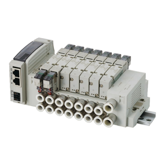
Discontinue 1 PRODUCT 1. PRODUCT base porting type body porting type Mounting plate Individual wiring type manifold Reduced wiring type manifold (The sketch shows DIN rail mount type) ... - Page 10 Discontinue 1 PRODUCT Flat cable connector(T50) Flat cable connector (T51) Serial transmission slave unit (T6*) DIN terminal box(B) ...
- Page 11 A set of terminals to control the valves mounted on the manifold. Serial transmission slave unit This is a slave station dedicated to a CKD-made manifold. DIN terminal box A green power indicator lamp is lit while the solenoid is energized.
-
Page 12: Port Indication And Si Unit System
Discontinue 2 SI UNIT 2. PORT INDICATION AND SI UNIT SYSTEM 2.1 Port Indication Each piping port is marked with ISO and JIS conformable piping port indication codes. Application Supply port Output port Output port Exhaust port Exhaust port Installing position of the solenoid valve is free. The position of the 4(A) and 5(R1) ports for 4G series are in reverse with 2(B) and 3(R2) ports respectively, compared with the 4K series. -
Page 13: Unpacking
Discontinue 3 UNPACKING 3. UNPACKING Bags containing solenoid valves should be opened only when you ! CAUTION : are ready to connect the valves to the pipes immediately afterward. If bags are opened before the valves are ready to be connected to the pipes, the entry of foreign matter from the piping ports could cause the solenoid valves to fail or malfunction. -
Page 14: Installation
Discontinue 4 INSTALLATION 4. INSTALLATION If you have to use the product under conditions that are different ! CAUTION : from the specified conditions or if you intend to use the product for a special application, be sure to consult us about the product specifications before using the product. -
Page 15: Installation
Discontinue 4 4 INSTALLATION 据 付 4.2 Installation When installing a solenoid valve unit, never attempt to hold it in ! WARNING : position by means of the pipes connected to it. ・ Fix the solenoid valve by applying the mounting screws and/or mounting plate to the solenoid valve. - Page 16 Discontinue 4 INSTALLATION 2) How to install Mounting plate(Option "P") For mounting plate of body porting individual valve, installation method may differ depending on single, double or 3-position. Incorrect installation may cause failures. For DIN terminal box type, it is restricted to the single solenoid type.
- Page 17 Discontinue 4 4 INSTALLATION 据 付 4.2.2 Mounting method of individual valve sub base type 4GE2 Series 4GE1 Series 2− 3.2 Mounting hole 2− 4.4 Mounting hole 4GE3 Series 2− 4.3 Mounting hole [SM-P00046-A] −16−...
- Page 18 Discontinue 4 INSTALLATION 4.2.3 How to install manifold How to install DIN rail A DIN rail mounting type manifold (Option symbol “D”) or a direct mounting type manifold which is modified using the DIN rail kit can be mounted on the DIN rail. If not mounted correctly, this may cause the manifold to drop or be damaged.
- Page 19 Discontinue 4 4 INSTALLATION 据 付 For direct mount M4G2/M4G3 series, through hole or internal thread hole is available for installation. When using the internal threads, select a mounting bolt that is screwed in by 10 threads or more, and note the tightening torque.
-
Page 20: Piping
Discontinue 4 INSTALLATION 4.3 Piping a) Observe the recommended tightening torque when connecting ! CAUTION : pipes. Observing the recommended tightening torque prevents air leakage and damage to the screw threads. To prevent damage to the screw threads, first use your hand to lightly tighten the screw and then use a tool to tighten the screw to the recommended torque. - Page 21 Discontinue 4 4 INSTALLATION 据 付 4.3.1 Seal material When using seal material, take care to avoid getting it in the pipes or overflowing on the exterior surface of the pipes. ●Seal Material (Paste or liquid) ●Seal Tape (Correct) (Incorrect) (Correct)
- Page 22 Discontinue 4 INSTALLATION 4.3.6 Pipe connections (1) Tubes to be used For use with solenoid valves with push-in joints, select tubes of the type specified by us: Soft nylon tubes (F-1500 Series) Urethane tubes (U-9500 Series) (2) For installation at a site that has spatters in the air, select incombustible tubes or metal pipes. (3) For a piping used for both hydraulic and pneumatic controls, select a hydraulic hose.
- Page 23 Discontinue 4 4 INSTALLATION 据 付 (8) Blank plug to be used For use with a solenoid valve with a push-in joint, select the blank plug specified by us: Blank plug GWP□-B Series [SM-P00046-A] −22−...
-
Page 24: Wiring
Discontinue 4 INSTALLATION 4.4 Wiring When carrying out electrical connections, please perform ! WARNING: disassembling and assembling work after reading the Instruction Manual carefully and with full understanding of its contents. ・ Your understanding of the structure of solenoid valve and its operation principle is required in order to secure the safety. - Page 25 Discontinue 4 4 INSTALLATION 据 付 4.4.2 How to use A-connector The A-connector is dedicated for the reduced wiring manifold, and is connected from the bottom. The same precaution as when using the E-connector is required when installing and removing the socket. When mounting and dismounting a socket, exercise the same caution as that when using E-type connectors.
- Page 26 Discontinue 4 INSTALLATION 2) Wiring (1) Press-fit a rod terminal [10] to the lead (stranded wire) of the cable [7]. Note that the solder less terminals must be prepared by the customer. For a single wire, the rod terminal is not necessary. A bare stranded wire can be used for wiring.
- Page 27 Discontinue 4 4 INSTALLATION 据 付 4.4.5 Common terminal stand type: Wiring style T10/T11 1) Points requiring your attention with common terminal stand type (T10/T11): (1) The internal common wiring for common terminal stand type has already been made. So, please unify the power source of manifold.
- Page 28 Discontinue 4 INSTALLATION 3) Wiring style T10 Maximum number of manifold station varies depending on the model. Please check the specifications for each model. Note) Valve No. 1a, 2a, 2b , etc. the numbers indicate the 1st station and 2nd station respectively, and alphabet (a) means the solenoid on a-side and (b) means the solenoid on b-side respectively.
- Page 29 Discontinue 4 4 INSTALLATION 据 付 Wiring style T11 Maximum number of manifold station varies depending on the model. Please check the specifications for each model. Note) Valve No. 1a, 2a, 2b , etc. the numbers indicate the 1st station and 2nd station respectively, and alphabet (a) means the solenoid on a-side and (b) means the solenoid on b-side respectively.
- Page 30 Discontinue 4 INSTALLATION 4.4.6 D sub-connector type : The connector for the T30 1) T30 connector The connector for the T30, which is usually called the D sub-connector, is widely used in FA and OA equipment. The 25P type, in particular, is the connector specified in the RS232C standard for use in personal computer communication.
- Page 31 Discontinue 4 4 INSTALLATION 据 付 4) Wiring style T30 Maximum number of manifold station varies depending on the model. Please check the specifications for each model. Note) Valve No. 1a, 2a, 2b , etc. the numbers indicate the 1st station and 2nd station respectively, and alphabet (a) means the solenoid on a-side and (b) means the solenoid on b-side respectively.
- Page 32 Discontinue 4 INSTALLATION 5) Connection to PLC The common wiring has been internally done on the manifold side. Since the electromagnetic valve has no polarity, it can be connected to either the NPN output or PNP output of the DC output unit of the PLC. Wire each unit in the following manner.
- Page 33 Discontinue 4 4 INSTALLATION 据 付 7) CKD cable specifications (CKD cables of the following models can be used) (Note 1) (Note 2) Model CABLE Note 1: Connecting method on the user side Note 2: Cable length L Cutting only With round crimp terminal for M3.5 screws...
- Page 34 Discontinue 4 INSTALLATION 4.4.7 Flat cable type : The connector for the T50 1) Flat cable connector The connector used in the T50 complies with the MIL standard (MIL-C-83503). Its flat-cable press-connection design makes wiring work easy. Pin numbers may differ from one PC manufacturer to another, but their functions are the same.
- Page 35 Discontinue 4 4 INSTALLATION 据 付 4) Wiring style T50 Maximum number of manifold station varies depending on the model. Please check the specifications for each model. Note) Valve No. 1a, 2a, 2b , etc. the numbers indicate the 1st station and 2nd station respectively, and alphabet (a) means the solenoid on a-side and (b) means the solenoid on b-side respectively.
- Page 36 Discontinue 4 INSTALLATION 5) Power supply The terminal stand is designed to accept power supplied from an external source when such outside power supply is needed. Supply the power to the wiring block or the input/output unit in the manner as shown in the following drawings.
- Page 37 Discontinue 4 4 INSTALLATION 据 付 4.4.8 Flat cable connector type : The connector for the T51/T52/T53 1) Cautions regarding the connector type (T51/T52/T53) (1) The order of signals in the PLC output unit should match the order of signals in the solenoid valve system.
- Page 38 Discontinue 4 INSTALLATION Wiring style T51 Maximum number of manifold station varies depending on the model. Please check the specifications for each model. Note) Valve No. 1a, 2a, 2b , etc. the numbers indicate the 1st station and 2nd station respectively, and alphabet (a) means the solenoid on a-side and (b) means the solenoid on b-side respectively.
- Page 39 Discontinue 4 4 INSTALLATION 据 付 Wiring style T52 Maximum number of manifold station varies depending on the model. Please check the specifications for each model. Note) Valve No. 1a, 2a, 2b , etc. the numbers indicate the 1st station and 2nd station respectively, and alphabet (a) means the solenoid on a-side and (b) means the solenoid on b-side respectively.
- Page 40 Discontinue 4 INSTALLATION Wiring style T53 Maximum number of manifold station varies depending on the model. Please check the specifications for each model. Note) Valve No. 1a, 2a, 2b , etc. the numbers indicate the 1st station and 2nd station respectively, and alphabet (a) means the solenoid on a-side and (b) means the solenoid on b-side respectively.
- Page 41 Discontinue 4 4 INSTALLATION 据 付 6) Connection to PLC The common wiring has been internally done on the manifold side. Since the electromagnetic valve has no polarity, it can be connected to either the NPN output or PNP output of the DC output unit of the PLC. Wire each unit in the following manner.
- Page 42 Discontinue 4 INSTALLATION 8) Cable The system uses flat cables or slender multi-conductor cables. As these cables have fine core wires, it should be checked that they have enough mechanical strength and electric capacity. Make sure to make a rounded corner (R) when bending the flat cable. The cable has large electric resistance (AWG28, approx.
-
Page 43: Proper Operation
Discontinue 5 OPERATION 5. PROPER OPERATION 5.1 Description of operation Valve operation 1) Description of Operation diagram (4GD1 series as an example) operation 4(A) 2(B) De-energized. (As shown in the diagram) 1(P) 2(B) 4(A) 5(R1) 4G**10 Single Energized 1(P) 4(A) 2(B) 3(R2) 5(R1) - Page 44 Discontinue 5 OPERATION Description of Operation diagram (4GD1 series as an example) operation 4(A) 2(B) De-energized. (As shown in the diagram) 4(A) 5(R1) 3GD*10 Normally Energized closed 1(P) 4(A) 5(R1) 1(P) 3(R2) 4(A) 2(B) De-energized. (As shown in the diagram) 1(P) 2(B) 3GD*110...
- Page 45 Discontinue 5 OPERATION 2) Manifold operation The main and pilot exhaust gases are collected in the manifold base and discharged from the exhaust port. 3) Prevention of malfunction A PR check valve is provided as a standard option. An exhaust malfunction prevention valve is provided when optionally selecting the symbol H.
-
Page 46: Manual Operation
Discontinue 5 OPERATION 5.2 Manual operation a) Once the manual operation device has been operated, ! WARNING: always return it to its origin (initial position), and then start the operation of the device. b) Before starting the manual operation, make sure that no one is around the cylinder to be operated. - Page 47 Discontinue 5 OPERATION 5.2.2 Operating the manual override (1) Push and non-lock operation Push the manual device in the direction indicated by an arrow until it is stopped. When the manual device is released, the manual operation is then cancelled. (2) Push and lock operation Push the manual device and turn it 90 in the direction indicated by an arrow.
-
Page 48: Air Quality
Discontinue 5 OPERATION 5.3 Air quality a) Do not supply air other than the compressed air. ! WARNING: b) Always use clean compressed air not including corrosive gas. a) A large amount of drain, oxidized oil, tar, foreign matter, and !... -
Page 49: Electric Circuit
Discontinue 5 OPERATION Always use compressed air without solid foreign matter. (1) Solid foreign matter of the compressed air enters the inside of the pneumatic device, causing the sliding part to be worn out or leading to sticking symptom. 5.3.5 Improvement of air quality The compressed air includes a large amount of drain (water, oxidized oil, tar, and/or foreign mater). -
Page 50: Maintenance
Discontinue 6 MAINTENANCE 6. MAINTENANCE 6.1 Periodic inspection Before providing a maintenance service, cut the power and the ! WARNING: supply of compressed air and confirm the absence of residual pressure. ・The above is required to ensure safety. Regularly perform the daily and periodic inspections to correctly !... -
Page 51: Disassembly And Reassembly
Discontinue 6 MAINTENANCE 6.2 Disassembly and reassembly Before providing maintenance service, cut the power and the supply ! WARNING: of compressed air and confirm residual pressure is released. ・The above is required to ensure safety. Regularly perform the daily and periodic inspections to correctly !... -
Page 52: Additional Installation Of A Valve Unit
Discontinue 6 MAINTENANCE 6.2.3 Replacement of cartridge joint Before changing the push-in joint size, check the proper work steps. If the cartridge joint is not mounted correctly or if the mounting screw is tightened insufficiently, this may cause air leak. 1) Direct piping (D) type (1) Remove the mounting screws. - Page 53 Discontinue 6 MAINTENANCE 6.3.2 Expanding at position with no reserved wiring When changing from the single to double type, internal wiring must be added to the b side solenoid to be expanded. Use the following procedures to expand the valves when reserved wiring is not provided. (1) ...
- Page 54 Discontinue 6 MAINTENANCE 6.3.4 Connection procedure of electric circuit board Connector and valve's compatibility on electric circuit board may differ depending on reduced wiring specifications (T10, T11, T30, T50, T51, T52, T53, T6*, T7*). When wiring the connector, always confirm the connector No.
- Page 55 Discontinue 6 MAINTENANCE Electric circuit board assembly Compatibility with valves −54− [SM-P00046-A]...
-
Page 56: Trouble Shooting
Discontinue TROUBLE SHOOTING 7. TROUBLE SHOOTING TROUBLE SHOOTING Motion troubles Suspected cause Remedies No electric signals Turn on the power Damage to signal wiring system Repair the control circuit Excessive fluctuating range of current or Reaffirm the power capacity. Does not actuate voltage (within ±10% of voltage fluctuation) The circuit is not wired correctly... -
Page 57: Product Specifications And How To Code Model Numbers
Discontinue 8 HOW TO ORDER 8. PRODUCT SPECIFICATIONS AND HOW TO CODE MODEL NUMBERS 8.1 Product specifications 1) Common specifications Model number 4G1・4G2・4G3 Item Working fluid Compressed air Operation method Pilot operated type Valve structure Soft spool valve Min. working pressure MPa Max. - Page 58 Discontinue 8 HOW TO ORDER Response time Item Two 3 -port valves − − built-in Response Single time 2-position − − − Double [ms] ABR port 3-position connection Values include the light surge suppressor. Response time is the value at an air supply of 0.5 MPa, 20℃, and oil-free. Changes based on pressure and quality of oil.
- Page 59 Discontinue 8 HOW TO ORDER 1(P) 4(A)/2(B) 4(A)/2(B) 5(R1)/3(R2) Model no. Position type C[dm /(s/bar)] C[dm /(s/bar)] 0.86 0.31 0.66 0.22 Two 3 -port valves built-in 0.99 0.20 0.70 0.12 2-position M3GD1 0.94 0.23 0.99 0.09 All ports blocked M4GD1 ABR port connection 3-position 0.93...
- Page 60 Discontinue 8 HOW TO ORDER 5) Weight Individual valve With sub base / Without sub base 3GA1 3GA2 3GA3 4GA1 4GA2 4GA3 4GB1 4GB2 4GB3 grommet lead 58/44 115/85 162/120 58/44 120/90 171/129 79/37 154/72 214/95 wire E-connector 60/46 117/87 164/122 60/46 122/92...
-
Page 61: How To Code Model Numbers
Discontinue 8 HOW TO ORDER 8.2 How to code model numbers Discrete valve: Body porting 4GD1 3GD1 Discrete valve for base installation 4GD1 Discrete 3 port valve for base installation (A) Model No 3GD1 Descriptions Sy mbol (B) Operator type 2-position single ● ● ● 2-position double ●... - Page 62 Discontinue 8 HOW TO ORDER (A) Model No Descriptions Sy mbol (D) Electric wire connection Blank Grommet lead wire(300mm) ● ● ● ● ● ● DIN terminal box ● ● ● ● E-connector (top/side common) Lead wire(300mm) ●...
- Page 63 Discontinue 8 HOW TO ORDER Discrete valve; sub-base porting 4GE1 3GE1 Discrete valve for base installation 4GE1 (A) Model No Discrete 3 port valve for base installation 3GE1 Descriptions Sy mbol (B) Operator type 2-position single ● ● ● 2-position double ● ● ● 3-position all port blocked ● ● ● 3-position ABR connection ●...
- Page 64 Discontinue 8 HOW TO ORDER (A) Model No Descriptions Sy mbol (D) Electric wire connection Blank Grommet lead wire(300mm) ● ● ● ● ● ● ● ● DIN terminal box E-connector (top/side common) ● ● ● ● ● Lead wire(300mm) E00 Lead wire(500mm) ●...
- Page 65 Discontinue 8 HOW TO ORDER Individual wiring manifold; body porting Manifold model no. 4GD1 3 port manifold model no. 3GD1 Discrete valve for base installation 4GD1 (A) Model No Discrete 3 port valve for base installation 3GD1 Descriptions Sy mbol (B) Operator type 2-position single ● ● ● 2-position double ● ● ● 3-position all port blocked ●...
- Page 66 Discontinue 8 HOW TO ORDER (A) Model No Descriptions Sy mbol (D) Electric wire connection Blank Grommet lead wire(300mm) ● ● ● ● ● ● DIN terminal box ● ● ● ● E-connector (top/side common) Lead wire(300mm) ●...
- Page 67 Discontinue 8 HOW TO ORDER Individual wiring manifold; sub-base porting Manifold model no. 4GE1 3 port manifold model no. 3GE1 Discrete valve for base installation 4GE1 (A) Model No Discrete 3 port valve for base installation 3GE1 Descriptions Sy mbol (B) Operator type 2-position single ● ● ● 2-position double ● ● ● 3-position all port blocked ●...
- Page 68 Discontinue 8 HOW TO ORDER (A) Model No Descriptions Sy mbol (D) Electric wire connection Blank Grommet lead wire(300mm) ● ● ● ● ● DIN terminal box ● ● ● E-connector (top/side common) Lead wire(300mm) ● ● ● ● ● ●...
- Page 69 Discontinue 8 HOW TO ORDER Reduced wiring manifold; body porting Manifold model no. 4GD1 3 port manifold model no. 3GD1 Discrete valve for base installation 4GD1 Discrete 3 port valve for base installation (A) Model No 3GD1 Descriptions Sy mbol (B) Operator type ● ● ● 2-position single ● ● ● 2-position double ● ● ● 3-position all port blocked 3-position ABR connection ●...
- Page 70 Discontinue 8 HOW TO ORDER (A) Model No Descriptions Sy mbol (D) Reduced wiring (light, surge absorber provided as standard) Left ● ● ● ● ● ● Common gland (M3 screw) T10R Right ● ● ● ● ● ● Left ● ● ● ● ● ● Common gland (push-in fitting) ●...
- Page 71 Discontinue 8 HOW TO ORDER Reduced wiring manifold; body porting; serial transmission Manifold model no. 4GD1 T6A0 3 port manifold model no. 3GD1 T6A0 Discrete valve for base installation 4GD1 Discrete 3 port valve for base installation (A) Model No 3GD1 Descriptions Sy mbol (B) Operator type 2-position single ● ● ● 2-position double ● ● ● 3-position all port blocked ●...
- Page 72 Discontinue 8 HOW TO ORDER (A) Model No Descriptions Sy mbol (D) Serial transmission (light and surge absorber provided as standard) UNIWIRE SYSTEM 8 points ● ● ● ● ● ● T6A0 UNIWIRE SYSTEM 16 points T6A1 ● ● ● ● ● ● OMRON CompoBus/S 8 points T6C0 ●...
- Page 73 Discontinue 8 HOW TO ORDER Reduced wiring manifold; sub-base porting Manifold model no. 4GE1 3 port manifold model no. 3GE1 Discrete valve for base installation 4GE1 Discrete 3 port valve for base installation (A) Model No 3GE1 Descriptions Sy mbol (B) Operator type 2-position single ● ● ● 2-position double ● ● ● 3-position all port blocked ●...
- Page 74 Discontinue 8 HOW TO ORDER (A) Model No Descriptions Sy mbol (D) Reduced wiring (light, surge absorber provided as standard) Left ● ● ● ● ● Common gland (M3 screw) ● ● ● ● ● T10R Right Left ● ● ● ● ● Common gland (push-in fitting) T11R Right ●...
- Page 75 Discontinue 8 HOW TO ORDER Reduced wiring manifold; sub-base porting; serial transmission Manifold model no. 4GE1 T6A0 3 port manifold model no. 3GE1 T6C0 Discrete valve for base installation 4GE1 (A) Model No Discrete 3 port valve for base installation 3GE1 Descriptions Sy mbol (B) Operator type 2-position single ● ● ● 2-position double ● ● ● 3-position all port blocked ●...
- Page 76 Discontinue 8 HOW TO ORDER (A) Model No Descriptions Sy mbol (D) Serial transmission (light and surge absorber provided as standard) UNIWIRE SYSTEM 8 points T6A0 ● ● ● ● ● UNIWIRE SYSTEM 16 points T6A1 ● ● ● ● ● OMRON CompoBus/S 8 points ● ● ● ● ● T6C0 OMRON CompoBus/S 16 points T6C1...
- Page 77 Discontinue 8 HOW TO ORDER 8.3 Option 1) Explanation of option ・With check valve: Symbol “H” Refer to 5.1 section. To prevent malfunction due to introduction of back pressure, a gasket with a malfunction prevention valve can be selected. ・Mounting plate: symbol "P" Refer to 4.2.3 section.
-
Page 78: Accessories
Discontinue 8 HOW TO ORDER 8.4 Accessories 1) Mounting rail All the angular corners are rounded. The mounting rail is cut at a mounting pitch of 12.5 mm. (pitch) Silencer SLM-M5 SLW-6A・8A・10A・8L・10L Port size Port size SLW-6S・8S Model Port Effective sectional Port size size area mm... -
Page 79: Kit Parts
Discontinue 8 HOW TO ORDER 8.5 Kit parts Commodity Part name Model 4G-Wiring type - Option - COIL - Voltage 1 : AC100V ... - Page 80 Discontinue 8 HOW TO ORDER Masking plate kit Model name Model Description 1 Masking plate 4G1-MP 1 Gasket 4G2-MP 2 Mounting screws 4G3-MP Mounting plate kit Model name Model Description 4G1-MOUNT-PLATE-KIT 1 Mounting plate, 2 Mounting screws, 2 Nut 4G2-MOUNT-PLATE-KIT 1 Mounting plate, 2 Mounting screws 4G3-MOUNT-PLATE-KIT 1 Mounting plate, 2 Mounting screws...
- Page 81 Discontinue 8 HOW TO ORDER 6) Reduced-wiring socket ass’y A 4G1 −SOCKET-ASSY−A R A − 2 2ND row to 24th row : Socket row number A or B : Solenoid position Blank or R : Connection type 4G1 or 4G2 or 4G3 : Series The wire-saving socket assembly A is used for manifold wiring.
- Page 82 Discontinue 8 HOW TO ORDER 8) PR check valves kit Model name Model Description 4G1-PR 2 PR check valves (for one unit) 4G2-PR 4G3-PR 9) Gasket with a malfunction prevention valve kit Model name Model Description 4G1-CHECK-VALVE 4G2-CHECK-VALVE 1 Gasket with check valve 4G3-CHECK-VALVE Gasket kit Model name...
- Page 83 Discontinue 8 HOW TO ORDER 15) M (Body porting valve, Individual wiring type) anifold base Model name Model Description M4GA1-00-[*4] 1 Manifold, 3 Pipe plugs M4GA2-00-[*4] M4GA3-00-[*4] * 4 No. of stations. Refer to 8.2 section. 16) Manifold base(Body porting , Fewer wiring) Model name Model Description...
- Page 84 Discontinue 8 HOW TO ORDER 21) Gasket for coil assembly Model Description 4G-COIL-GASKET 1 Gasket 22) Mounting screw for coil assembly (One set: 10 screws) Model Description 4G-COIL-SET-SCREW 10 Mounting screws (for 5 units) 23) Serial transmission slave unit Wiring type Model Description T6A0...
Need help?
Do you have a question about the 3GD/E1 Series and is the answer not in the manual?
Questions and answers