Table of Contents
Advertisement
Quick Links
Advertisement
Table of Contents

Related Manuals for CKD GHV Series


Summary of Contents for CKD GHV Series
- Page 1 SM-50767-A INSTRUCTION MANUAL Gas Combustion Combination Valve GHV Series ● Read this manual carefully and thoroughly before using this product. ● Pay extra attention to the instructions concerning safety. ● After reading this manual, keep it in a safe and...
- Page 2 It is important to select, operate, handle, and maintain CKD products appropriately to ensure that each CKD product is used safely. Please observe all warnings and precautions for each CKD product to ensure the safety of not only the CKD products but also your device containing CKD products.
- Page 3 • Determination of compatibility It is the responsibility of the customer to determine whether the CKD product is compatible with the system, machinery, and/or device with which the product is to be used.
-
Page 4: Table Of Contents
SM-50767-A Contents Page 1 Inspections upon delivery 1-1 Product appearance ...................... 1-2 Nameplate information ....................1-3 Product storage ......................2 Installation 2-1 Installation environment ....................2-2 Mounting ........................2-3 Piping ........................... 2-4 Wiring .......................... 3 Inspections before operation 3-1 Conformity with specifications ................... 11 3-2 Actuation ........................ -
Page 5: Inspections Upon Delivery
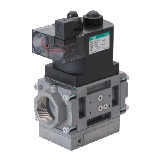
SM-50767-A 1 Inspections upon delivery 1-1 Product appearance Check the product’s exterior appearance for any abnormality by thoroughly inspecting the product for any damage or loose bolts that may have occurred during transportation. 1-2 Nameplate information Check the model number, specification, and any other information printed on the product nameplate. Model number Rated voltage (VAC) Apparent power (VA) -
Page 6: Installation
SM-50767-A 2 Installation 2-1 Installation environment a) Do not use this product in the presence of corrosive gas or in an atmosphere that may affect the material of construction. WARNING b) Do not install this product in locations subject to vibration and shock. c) Do not expose this product to direct sunlight, rain, and wind. -
Page 7: Piping
SM-50767-A 2-2-3 Flow direction Mount the product so the direction of the arrow on the product corresponds to the direction of gas flow. 2-2-4 Filter installation Install a filter upstream of the product to remove dust and other foreign matter. Filter 2-2-5 Space around the product Provide an access space of about 20 cm wide around the product for inspection and maintenance. -
Page 8: Wiring
SM-50767-A 2-3-3 Length of pipe thread For the gas pipe thread length, observe the effective thread length. Too long or too short may result in damage and leakage. Make sure to file off about one-half pitch of thread from the end. 2-3-4 Mounting and piping Before mounting this product on the pipes, attach flanges to pipe ends and align the flanges in a straight line. - Page 9 SM-50767-A 2-4-2 Fuse installation When installing a fuse in the power circuit, make sure to use a fuse of appropriate capacity. 2-4-3 Operating power source connection (1) When connecting the power source, properly connect the high voltage and ground wiring as shown below. High voltage High voltage Combustion...
- Page 10 SM-50767-A Once wiring is complete, turning on the power actuates the 2 solenoid valves constituting the product. Whether or not the power is on can be determined from the LED lights on the electrical part of the product. LED lights 2-4-4 Wiring of closed position indicator switch (Option: E) [Connecting to DIN terminal] 1) Strip away lead sheath and pass leads through cap, washer, gasket, and DIN terminal box case.
-
Page 11: Inspections Before Operation
SM-50767-A 2-4-5 Surge voltage prevention When connecting the product and inductive load (such as motor, relays) in parallel, wire them as shown below so the surge voltage is not applied to the product. 3 Inspections before operation 3-1 Conformity with the specifications Make sure operating conditions such as voltage and gas pressure are in conformity with the specifications on the product nameplate. -
Page 12: Heat Generation Of Coil
SM-50767-A · Internal leakage Primary-side valve Product (both valves open/close simultaneously) Water column gauge Secondary-side valve Test Valve 2 Valve 1 cock 1 Test Intermediate Test cock 3 pressure cock 2 Graduated cylinder detection port Procedure 1: Test for leakage of gas pipes a) Close valve 2. -
Page 13: Proper Operation
SM-50767-A 4 Proper operation 4-1 Precautions a) This product is not for use as an emergency shutoff valve. · This product is not designed to provide safety protection, like that provided by an emergency shutoff valve. If this product is used in a system which requires safety measures, make sure to adopt other WARNING reliable safety measures. -
Page 14: Pressure Adjustment
SM-50767-A 4-2 Pressure adjustment ※, This feature is available only on GHV-G- “solenoid valve with built-in governor + solenoid valve” type models. [Adjusting the pressure] Loosen and remove the governor cap (the taller cap). Adjust pressure by turning the pressure-adjusting screw with a flat blade screwdriver. -
Page 15: Start Gas Adjustment
SM-50767-A 4-3 Start gas adjustment ※, This feature is available only on GHV-L- “solenoid valve + solenoid valve (slow open)” type models. [Adjusting the start gas] To adjust the start gas, turn the damper assembly as shown below to change the flow rate of start gas. Slotted flat fillister head machine screw Screws with red paint (3 screws) (Do not loosen them.) -
Page 16: Periodic Inspection
Conduct actuation and leakage tests at least once a year (refer to sections 3-2 and 3-3). For repairs in case of abnormal actuation, contact the dealer from whom you made your purchase or your nearest CKD agent. Conduct periodic inspections according to the periodic inspection procedures for safety shutoff valves given in safety standards such as those listed below. -
Page 17: Troubleshooting
(Do not disassemble the product.) internal sliding parts CKD agent. If voltage is applied, inspect a. Control electric circuit Measure voltage at terminal block and repair the electric has failed inside DIN terminal box. -
Page 18: Product Specification And Model Number
SM-50767-A 7 Product specification and model number 7-1 Product application This product is used in gas passages as a gas shutoff valve and controls the ON and OFF supply of gas fuel within industrial gas combustion equipment. (This product is not for use as an emergency shutoff valve.) An example of how this product can be applied in a gas combustion system is shown below. -
Page 19: Product Specification
SM-50767-A 7-3 Product specification GHV-G GHV-N GHV-L Variation Solenoid valve with built-in Solenoid valve + Solenoid valve + Description governor + solenoid valve solenoid valve solenoid valve (slow open) Port size -D25 -D32 -D40 -D50 -D25 -D32 -D40 -D50 -D25 -D32 -D40 -D50... -
Page 20: Closed Position Indicator Switch Specification
SM-50767-A 7-5 Closed position indicator switch specification ※ This section is only for GHV- -E, models with closed position indicator switch (option). Ambient temperature for models with closed position indicator switch is -15°C to 60°C. CAUTION Under low temperatures, micro switch takes longer time to operate when the valve is open (about 5 seconds at -15°C). -
Page 21: Internal Structure And Outside Dimensions
SM-50767-A 8 Internal structure and outside dimensions 8-1 Internal structure · GHV-G (Solenoid valve with built-in governor + solenoid valve) · GHV-N (Solenoid valve + solenoid valve) · GHV-L (Solenoid valve + solenoid valve (slow open)) Part name Part name Part name Pressure-adjusting screw O-ring... -
Page 22: Outside Dimensions
SM-50767-A 8-2 Outside dimensions ● Solenoid valve with built-in governor + solenoid valve GHV-G-D25 and -D32 Rp 1/8 x 2 (both sides flanged) (Pressure detection port) Rp 1/8 x 2 (both sides) (Secondary-side Rp 1/8 x 2 (both sides) pressure detection port) (Intermediate 2: port size pressure detection port) - Page 23 SM-50767-A ● ● Solenoid valve + solenoid valve Solenoid valve + solenoid valve (slow open) GHV-N-D25 to -D50 GHV-L-D25 to -D50 ● Models with closed position indicator switch GHV-G-D25- to -D50-E GHV-N-D25- to -D50-E - 23 -...
-
Page 24: Reference Materials
SM-50767-A 9 Reference materials 9-1 Flow characteristics GHV-※-D25 GHV-※-D32 GHV-※-D40 GHV-※-D50 1000 9-2 Flow rate conversion factor Corresponding flow rate = (Flow rate from above table) x (factor) Natural gas City gas Gas type Propane (13A) (6B, 6C) Specific gravity 0.65 0.54 Factor...
Need help?
Do you have a question about the GHV Series and is the answer not in the manual?
Questions and answers