Table of Contents
Advertisement
Quick Links
Advertisement
Table of Contents

Related Manuals for Rohde & Schwarz R&S RTB2000


Summary of Contents for Rohde & Schwarz R&S RTB2000
- Page 1 ® R&S RTB2000 Oscilloscope User Manual (=Q@;2) 1333161102 Version 11...
- Page 2 ® This manual describes the following R&S RTB2000 models with firmware version 2.4xx: ● ® R&S RTB2002 (1333.1005K02) ● ® R&S RTB2004 (1333.1005K04) © 2021 Rohde & Schwarz GmbH & Co. KG Mühldorfstr. 15, 81671 München, Germany Phone: +49 89 41 29 - 0 Email: info@rohde-schwarz.com Internet:...
-
Page 3: Table Of Contents
® Contents R&S RTB2000 Contents 1 Preface....................19 Safety and regulatory information................19 1.1.1 Safety instructions......................19 1.1.2 Labels on the product....................24 1.1.3 Warning messages in the documentation..............24 1.1.4 CE declaration of conformity..................25 1.1.5 UKCA declaration of conformity..................26 1.1.6 Korea certification class A.....................27 Documentation overview....................27 1.2.1... - Page 4 ® Contents R&S RTB2000 2.2.1.2 Other connectors on the front panel................36 2.2.2 Rear panel........................37 3 Operating basics.................. 39 Display overview......................39 Selecting the application....................40 Using the touchscreen....................40 3.3.1 Accessing functionality using the main menu............... 40 3.3.2 Accessing functionality using shortcuts.................42 3.3.3 Entering data.........................42 3.3.4...
- Page 5 ® Contents R&S RTB2000 4.5.1 Shortcuts for acquisition settings.................. 67 4.5.2 Acquisition settings....................... 67 5 Trigger....................71 Trigger controls......................72 Shortcuts for trigger settings..................73 General trigger settings....................74 Edge trigger......................... 76 Width trigger........................ 78 Video trigger........................ 80 Pattern trigger......................82 Timeout trigger......................85 Actions on trigger.......................
- Page 6 ® Contents R&S RTB2000 6.4.1 Segmented memory....................107 6.4.2 Activating the history....................108 6.4.3 History settings......................108 6.4.4 Segment table and history player................110 6.4.5 Exporting history data....................113 6.4.5.1 Saving history to file....................113 6.4.5.2 File organization and content..................114 Search........................115 6.5.1 Search conditions and results..................
- Page 7 ® Contents R&S RTB2000 8.1.2 Using masks........................148 8.1.3 Mask window.......................151 8.1.4 Mask menu........................152 FFT analysis......................155 8.2.1 FFT display......................... 155 8.2.2 Performing FFT analysis..................... 157 8.2.3 FFT setup........................157 8.2.3.1 Short menu for FFT.....................157 8.2.3.2 Settings in the FFT window..................158 8.2.3.3 FFT menu........................159 XY-Diagram........................
-
Page 8: Gray) = The
® Contents R&S RTB2000 Quick save with onetouch..................185 Export and import..................... 186 10 General instrument setup..............189 10.1 Instrument settings....................189 10.2 Display settings......................192 10.3 Reset.......................... 195 10.4 Locking the touchscreen..................196 10.5 Performing a self-alignment..................196 10.6 Setting the date, time and language................197 10.7 Options........................199 10.7.1... - Page 9 ® Contents R&S RTB2000 12.1.2 Displaying decode results................... 214 12.1.3 Bus table: decode results....................215 12.1.4 Bus labels........................217 12.1.5 Label list........................218 12.1.5.1 Using label lists......................218 12.1.5.2 Content and format of the PTT file................219 12.2 SPI bus (option R&S RTB-K1)..................221 12.2.1 The SPI protocol......................
- Page 10 ® Contents R&S RTB2000 12.6.4 LIN decode results...................... 265 12.6.5 Search on decoded LIN data..................266 12.6.6 LIN label list.........................269 13 Logic analyzer (option R&S RTB-B1, MSO)........272 13.1 Short menu for logic channels................272 13.2 Logic analyzer settings.................... 274 13.3 Triggering on logic channels...................
- Page 11 ® Contents R&S RTB2000 15.2.1 Documenting results....................303 15.2.1.1 Saving screenshots to file................... 303 15.2.1.2 Saving, copying, and loading setup data..............304 15.2.1.3 Reading waveform data in real format................ 305 15.2.1.4 Reading waveform data in unsigned integer format............305 Data conversion......................306 15.2.2 Firmware update......................
- Page 12 ® Contents R&S RTB2000 15.6.1 Zoom........................... 345 15.6.2 Mathematics........................346 15.6.3 Reference waveforms....................350 15.6.4 Search.........................355 15.6.4.1 General search settings....................355 15.6.4.2 Edge search configuration..................357 15.6.4.3 Width search configuration..................357 15.6.4.4 Peak search configuration...................359 15.6.4.5 Rise/fall time search configuration................360 15.6.4.6 Runt search configuration...................
- Page 13 ® Contents R&S RTB2000 15.8.2.4 Mask data........................406 15.8.3 FFT analysis........................407 15.8.3.1 General settings......................407 15.8.3.2 Frequency settings......................409 15.8.3.3 Time settings....................... 411 15.8.3.4 Waveform settings.......................411 15.8.3.5 Waveform data......................412 15.8.4 XY-Waveforms......................415 15.8.5 Digital voltmeter......................416 15.8.6 Trigger counter......................418 15.8.7 Bode plot (option R&S RTB-K36)................419 15.8.7.1 Bode plot setup......................
- Page 14 ® Contents R&S RTB2000 15.11 Serial bus analysis....................463 15.11.1 General........................463 15.11.2 SPI (option R&S RTB-K1)................... 466 15.11.2.1 SPI (with CS)- configuration..................466 15.11.2.2 SPI (no CS) - configuration..................469 15.11.2.3 SPI - trigger......................... 473 15.11.2.4 SPI - decode results....................475 15.11.3 I²C (option R&S RTB-K1)....................
- Page 15 ® Contents R&S RTB2000 15.12.2.3 Parallel buses - decode results................... 539 15.13 Signal generation (option R&S RTB-B6)..............541 15.13.1 Function generator...................... 541 15.13.1.1 Basic settings of the function generator..............541 15.13.1.2 Arbitrary waveform setup.................... 544 15.13.1.3 Burst settings......................546 15.13.1.4 Modulation settings.....................
- Page 16 ® Contents R&S RTB2000 A.1.3 SCPI parameters......................569 A.1.3.1 Numeric values......................570 A.1.3.2 Special numeric values....................570 A.1.3.3 Boolean parameters....................571 A.1.3.4 Text parameters......................571 A.1.3.5 Character strings......................571 A.1.3.6 Block data........................572 A.1.4 Overview of syntax elements..................572 A.1.5 Structure of a command line..................573 A.1.6 Responses to queries....................
- Page 17 ® Contents R&S RTB2000 B.4.4 Error queue......................... 589 Reset values of the status reporting system............589 List of commands................591 User Manual 1333.1611.02 ─ 11...
- Page 18 ® Contents R&S RTB2000 User Manual 1333.1611.02 ─ 11...
-
Page 19: Preface
® Preface R&S RTB2000 Safety and regulatory information 1 Preface 1.1 Safety and regulatory information The product documentation helps you to use the product safely and efficiently. Follow the instructions provided here and in the Chapter 1.1.1, "Safety instructions", on page 19. Intended use The R&S RTB2000 oscilloscope is designed for measurements on circuits that are only indirectly connected to the mains or not connected at all. - Page 20 ® Preface R&S RTB2000 Safety and regulatory information aged or broken, stop using the product. Contact Rohde & Schwarz customer service at http://www.customersupport.rohde-schwarz.com. In these safety instructions, the term "product" covers instruments (oscilloscopes), probes and their accessories. Lifting and carrying the instrument Check the data sheet for the maximum weight of the instrument.
- Page 21 ® Preface R&S RTB2000 Safety and regulatory information Connecting to power and grounding The mains power supply input of the instrument complies with overvoltage category II. It has to be connected to a fixed installation used to supply energy-consuming equip- ment such as household appliances and similar loads.
- Page 22 ® Preface R&S RTB2000 Safety and regulatory information defined in the data sheet. If you use other than Rohde & Schwarz accessories, make sure that they are suitable for the instrument and the measurement task. ● Set the correct attenuation factor on the instrument according to the probe being used.
- Page 23 ® Preface R&S RTB2000 Safety and regulatory information – Eddy current loss can cause heating of the sensor head. – Dielectric heating can cause heating of cord insulation and other materials. Measurement categories IEC 61010-2-030 defines measurement categories that rate instruments on their ability to resist short transient overvoltages that occur in addition to the working voltage.
-
Page 24: Labels On The Product
® Preface R&S RTB2000 Safety and regulatory information Potential hazard Read the product documentation to avoid personal injury or product damage. Electrical hazard Indicates live parts. Risk of electric shock, fire, personal injury or even death. Protective conductor terminal Connect this terminal to a grounded external conductor or to protective ground. This protects you against electric shock should an electric problem occur. -
Page 25: Ce Declaration Of Conformity
® Preface R&S RTB2000 Safety and regulatory information 1.1.4 CE declaration of conformity User Manual 1333.1611.02 ─ 11... -
Page 26: Ukca Declaration Of Conformity
® Preface R&S RTB2000 Safety and regulatory information 1.1.5 UKCA declaration of conformity User Manual 1333.1611.02 ─ 11... -
Page 27: Korea Certification Class A
® Preface R&S RTB2000 Documentation overview 1.1.6 Korea certification class A 이 기기는 업무용(A급) 전자파 적합기기로서 판매자 또는 사용자는 이 점을 주의하시기 바라며, 가정외의 지역에서 사용하는 것을 목적으로 합니다. 1.2 Documentation overview This section provides an overview of the R&S RTB2000 user documentation. 1.2.1 Manuals and instrument help You find the manuals on the product page at: www.rohde-schwarz.com/manual/rtb2000... -
Page 28: Data Sheet And Brochure
® Preface R&S RTB2000 Conventions used in the documentation Service manual Describes the performance test for checking the rated specifications, module replace- ment and repair, firmware update, troubleshooting and fault elimination, and contains mechanical drawings and spare part lists. The service manual is available for regis- tered users on the global Rohde &... -
Page 29: Conventions For Procedure Descriptions
® Preface R&S RTB2000 Conventions used in the documentation Convention Description Input Input to be entered by the user is displayed in italics. Links Links that you can click are displayed in blue font. "References" References to other parts of the documentation are enclosed by quota- tion marks. -
Page 30: Getting Started
® Getting started R&S RTB2000 Preparing for use 2 Getting started 2.1 Preparing for use Here, you can find basic information about setting up the instrument for the first time or when changing the operating site. 2.1.1 Lifting and carrying See: "Lifting and carrying the instrument"... -
Page 31: Setting Up The Product
® Getting started R&S RTB2000 Preparing for use Electromagnetic compatibility classes The electromagnetic compatibility (EMC) class indicates where you can operate the product. The EMC class of the product is given in the data sheet under "General data". ● Class B equipment is suitable for use in: –... -
Page 32: Mounting The Product In A Rack
® Getting started R&S RTB2000 Preparing for use As an alternative, you can mount several products in a rack. 4. NOTICE! Overheating can damage the product. Prevent overheating as follows: ● Keep a minimum distance of 10 cm between the fan openings of the product and any object in the vicinity. -
Page 33: Connecting To Power
® Getting started R&S RTB2000 Preparing for use Cable selection and electromagnetic interference (EMI) Electromagnetic interference (EMI) can affect the measurement results. To suppress electromagnetic radiation during operation: ● Use high-quality shielded cables, for example, double-shielded RF and LAN cables. ●... -
Page 34: Switching On Or Off
® Getting started R&S RTB2000 Preparing for use The required ratings are listed next to the AC power connector and in the data sheet. 2.1.7 Switching on or off The instrument is switched on or off with the power switch and the [Standby] key. Table 2-1: Overview of power states Status Power switch... -
Page 35: Instrument Tour
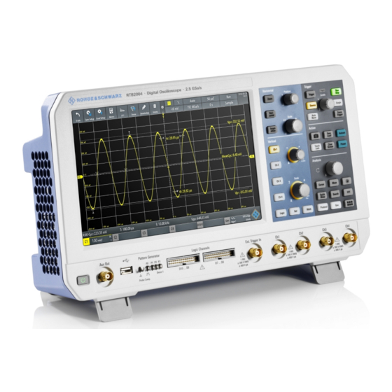
® Getting started R&S RTB2000 Instrument tour 2. Disconnect the product from the power source. 2.2 Instrument tour 2.2.1 Front panel Figure 2-1 shows the front panel of the R&S RTB2000. The function keys are grouped in functional blocks to the right of the display. Figure 2-1: Front panel of R&S RTB2004 with 4 input channels 1 = Display 2 = Horizontal and vertical setup controls... -
Page 36: Input Connectors
® Getting started R&S RTB2000 Instrument tour 2.2.1.1 Input connectors BNC inputs (4 and 5) The R&S RTB2000 has two or four channel inputs (4) to connect the input signals. The external trigger input (5) is used to control the measurement by an external signal. The trigger level can be set from -5 V to 5 V. -
Page 37: Rear Panel
® Getting started R&S RTB2000 Instrument tour [Pattern Generator] (7) Connectors for the pattern generator P0, P1, P2, P3. The "Demo 1" signal is intended for demonstration purposes. [Probe Comp.] (7) Probe compensation terminal to support adjustment of passive probes to the oscillo- scope channel. - Page 38 ® Getting started R&S RTB2000 Instrument tour 1 = LAN connector 2 = USB connector, type B 3 = AC power supply connector and main power switch 4 = Kensington lock slot to secure the instrument against theft 5 = Loop for lock to secure the instrument against theft 6 = not used [LAN] (1) 8-pin connector RJ-45 used to connect the instrument to a Local Area Network (LAN).
-
Page 39: Operating Basics
® Operating basics R&S RTB2000 Display overview 3 Operating basics 3.1 Display overview The touchscreen display of the instrument shows the waveforms and measurement results, and also information and everything that you need to control the instrument. Figure 3-1: Display of the R&S RTB2000 with 4 channels 1 = Toolbar 2 = Trigger source, main trigger parameter (here: slope for edge trigger), trigger level 3 = Trigger mode and sample rate... -
Page 40: Selecting The Application
® Operating basics R&S RTB2000 Using the touchscreen 3.2 Selecting the application The "Apps Selection" dialog provides fast access to all available applications. ► There are several ways to open the "Apps Selection" dialog: ● Press the [Apps Selection] key. ●... - Page 41 ® Operating basics R&S RTB2000 Using the touchscreen Figure 3-2: Open the main menu and select a menu item Figure 3-3: Switch on or off (left) and select a parameter value (right) ► To close the menu: User Manual 1333.1611.02 ─ 11...
-
Page 42: Accessing Functionality Using Shortcuts
® Operating basics R&S RTB2000 Using the touchscreen Tap "Back", or tap into the diagram outside the menu. 3.3.2 Accessing functionality using shortcuts The labels in information bar at the top of the display, the channel labels and also the results at the bottom provide shortcuts to the most important settings. -
Page 43: Using Gestures
® Operating basics R&S RTB2000 Using the touchscreen Figure 3-5: Enter numerical value and unit 3.3.4 Using gestures Drag one finger Drag horizontally in the diagram to change the horizontal position of all waveforms. In frequency domain, the center frequency is changed. Drag vertically in the diagram to change the vertical position of the selected waveform. -
Page 44: Front Panel Keys
® Operating basics R&S RTB2000 Front panel keys Spread or pinch two fingers in horizontal direction to change the horizontal scale of all waveforms. In frequency domain, the frequency span is changed. Swipe two fingers If the history option R&S RTB-K15 is installed, swipe two fingers in the diagram to scrolls through the history segments. -
Page 45: Analysis Controls
® Operating basics R&S RTB2000 Front panel keys [Clear Screen] Deletes all waveforms, annotations and the measurement results of deleted wave- forms. All settings remain unchanged. Remote command: on page 450 DISPlay:CLEar[:SCReen] 3.4.2 Analysis controls The controls in the [Analysis] functional block open various menus for signal analysis. [Navigation] The function of this universal rotary knob depends on the usage context: ●... -
Page 46: Using The Toolbar
® Operating basics R&S RTB2000 Using the toolbar Press the key to stop quick measurements. Note: Channels other than the selected one are switched off in quick measurement mode. When you activate quick measurements, cursor measurements are automati- cally deactivated. Deactivate quick measurements before selecting the cursors. [Search] Enables the search with the last configured setup. -
Page 47: Quick Access
® Operating basics R&S RTB2000 Quick access 2. Disable the functions that you do not need. 3. Tap the functions that you need. You can select maximum 8 functions. 4. Close the dialog box. 3.6 Quick access If the measurement task requires to change the settings from different menus repeat- edly, you can use the "QuickAccess". -
Page 48: Menu History
® Operating basics R&S RTB2000 Menu history c) Repeat steps a) and b) for each setting and function that you need for the mea- surement task. 3. To remove unwanted settings and functions: a) Tap the "Settings" icon of the function. b) To delete the selected setting or function, tap "Delete". -
Page 49: Getting Help
® Operating basics R&S RTB2000 Getting help 3.8 Getting help In most menus and dialogs, graphics explain the meaning of the selected setting. For further information, you can open the help, which provides functional description of selected setting. To open the help window 1. -
Page 50: Waveform Setup
® Waveform setup R&S RTB2000 Connecting probes and displaying a signal 4 Waveform setup This chapter describes how to connect and set up probes, to adjust the horizontal and vertical settings, and to control the acquisition. 4.1 Connecting probes and displaying a signal Risk of instrument damage Make sure to set the attenuation factor on the instrument according to the probe being used. -
Page 51: Horizontal Setup
® Waveform setup R&S RTB2000 Horizontal setup 1 Ω resistor and a 10:1 probe is used, the V/A-value of the resistor is 1 V/A. The attenuation factor of the probe is 0.1, and the resulting current probe attenuation is 100 mV/A. 5. - Page 52 ® Waveform setup R&S RTB2000 Horizontal setup the horizontal acquisition window to the waveform section of interest, you can use the following parameters: ● The horizontal position defines the time distance of the trigger point (the zero point of the diagram) to the reference point. Changing the horizontal position, you can move the trigger point, even outside the screen.
-
Page 53: Horizontal Controls
® Waveform setup R&S RTB2000 Horizontal setup 4.2.1 HORIZONTAL controls [Position] Changes the trigger position, the time distance from the trigger point to the reference point (trigger offset). The trigger point is the zero point of the diagram. Thus, you can set the trigger point even outside the diagram and analyze the signal some time before or after the trigger. -
Page 54: Shortcuts For Horizontal Settings
® Waveform setup R&S RTB2000 Horizontal setup [Horizontal] Opens the menu to configure horizontal scale, position, and reference point. The cur- rent scale and position is shown in the top information bar. If zoom is active, you can find also the zoom scale and zoom position in this menu. [Acquisition] Opens the "Acquisition"... -
Page 55: Vertical Setup
® Waveform setup R&S RTB2000 Vertical setup The reference point defines which part of the waveform is shown. By default, the refer- ence point is displayed in the center of the window, and you can move it to the left or right. -
Page 56: Vertical Controls
® Waveform setup R&S RTB2000 Vertical setup There are several ways to adjust vertical settings: ● Use the controls in the Vertical functional block of the front panel to select the channel, to scale the waveform, and to set the position. ●... - Page 57 ® Waveform setup R&S RTB2000 Vertical setup [Offset/Position (upper knob)] The upper vertical knob adjusts the following, depending on the selected waveform: ● Offset or position of an analog channel (adjustable: main menu > "Vertical"). The visual effect is the same. While the offset sets a voltage, position is a graphical set- ting given in divisions.
-
Page 58: Short Menu For Analog Channels
® Waveform setup R&S RTB2000 Vertical setup [Math] Displays the math waveforms with their last configuration. A math waveform is a wave- form that is calculated from the captured data. The second keypress opens the menu, where you can activate and configure math waveforms, and save and load equation sets. - Page 59 ® Waveform setup R&S RTB2000 Vertical setup b) Select "Vertical". 2. Select the parameter that is assigned to the upper vertical knob: "Offset" or "Posi- tion". 3. Open the channel menu. ► To open the channel menu directly, press the corresponding channel key. If the channel was active but not selected, press twice: Once to select the wave- form, and next to open the short menu.
- Page 60 ® Waveform setup R&S RTB2000 Vertical setup Vert. Position Knob Selects the parameter to be changed with the [Offset/Position (upper knob)]: "Offset" or "Position". By default, position is set. [Preset] does not affect the assignment. Channel <n> Opens the channel menu. State Switches the selected channel on or off.
- Page 61 ® Waveform setup R&S RTB2000 Vertical setup Remote command: on page 317 CHANnel<m>:BANDwidth Vertical Scale Sets the vertical scale in Volts per division to change the displayed amplitude of the selected waveform. The current value is shown in the waveform label below the grid. Vertical scale directly affects the resolution of the waveform amplitude.
-
Page 62: Threshold Settings
® Waveform setup R&S RTB2000 Vertical setup Deskew compensates delay differences between channels caused by the different length of cables, probes, and other sources. Correct deskew values are important for accurate triggering. Signals that are routed over lines with different lengths have a dif- ferent propagation delay. -
Page 63: Label Settings
® Waveform setup R&S RTB2000 Vertical setup Threshold A threshold is used for digitization of analog signals. If the signal value is higher than the threshold, the signal state is high (1 or true for the Boolean logic). Otherwise, the signal state is considered low (0 or false) if the signal value is below the threshold. -
Page 64: Probes
® Waveform setup R&S RTB2000 Probes Label Activates or deactivates the label display. The label is shown at the waveform on the right edge of the display. Remote command: on page 321 CHANnel<m>:LABel:STATe on page 320 CHANnel<m>:LABel Predefined Label Selects a predefined label text. You can edit the text with "Edit Label". Edit Label Opens on-screen keypad to enter a label text. -
Page 65: Probe Settings
® Waveform setup R&S RTB2000 Probes Two connector pins for compensation are at the front panel. The left pin is on ground level. The next pin supplies a square wave signal for the adjustment. 1. Press the [Apps Selection] key. 2. -
Page 66: Acquisition Setup
® Waveform setup R&S RTB2000 Acquisition setup User If default values do not fit, you can enter an arbitrary attenuation factor. The vertical scaling and measured values are multiplied by this factor so that the displayed values are equal to the undivided measured signal values. Remote command: on page 321 PROBe<m>:SETup:ATTenuation:MANual... -
Page 67: Shortcuts For Acquisition Settings
® Waveform setup R&S RTB2000 Acquisition setup 4.5.1 Shortcuts for acquisition settings To adjust the acquisition mode, and to perform a single acquisition, you can use the shortcuts on the top of the display. The labels show the current values. 1 = start or stop a continuous acquisition, or start a single acquisition if [Single] is active 2 = adjust the acquisition mode 3 = shows the current sample rate for information... - Page 68 ® Waveform setup R&S RTB2000 Acquisition setup Remote command: on page 325 ACQuire:POINts:AUTomatic on page 325 ACQuire:POINts[:VALue] Acquire Mode Defines how the waveform is built from the captured samples. There are two general methods to build the waveform record: sample decimation and waveform arithmetic. Sample decimation reduces the data stream of the ADC to a stream of waveform points with lower sample rate and a less precise time resolution.
- Page 69 ® Waveform setup R&S RTB2000 Acquisition setup "Enve- Each acquisition is done in peak detect mode, and the most extreme lope + PD" values of all consecutive acquisitions build the envelope. This method is more precise than "Envelope". Remote command: on page 326 ACQuire:TYPE on page 327...
- Page 70 ® Waveform setup R&S RTB2000 Acquisition setup Interpolation Selects the interpolation method if interpolation is required to get the defined record length. "Sin(x)/x" Two adjacent ADC sample points are connected by a sin(x)/x curve, and also the adjoining sample points are considered by this curve. The interpolated points are placed on the resulting curve.
-
Page 71: Trigger
® Trigger R&S RTB2000 5 Trigger Triggering means to capture the interesting part of the relevant waveforms. Choosing the right trigger type and configuring all trigger settings correctly allows you to detect various incidents in signals. A trigger occurs if the trigger conditions are fulfilled. The instrument acquires continu- ously and keeps the sample points to fill the pretrigger part of the waveform record. -
Page 72: Trigger Controls
® Trigger R&S RTB2000 Trigger controls 5.1 Trigger controls The keys and the rotary knob in the Trigger functional block adjust the trigger and start or stop acquisition. The green LED above the [Levels] knob lights up when the instrument triggers. [Trigger] Opens the "Trigger"... -
Page 73: Shortcuts For Trigger Settings
® Trigger R&S RTB2000 Shortcuts for trigger settings Remote command: on page 333 TRIGger:A:LEVel<n>[:VALue] on page 333 TRIGger:A:FINDlevel [Force Trigger] Provokes an immediate single acquisition. Use this key if the acquisition is running in normal mode and no valid trigger occurs. Thus, you can confirm that a signal is availa- ble and use the waveform display to determine how to trigger on it. -
Page 74: General Trigger Settings
® Trigger R&S RTB2000 General trigger settings 1 = adjust the trigger source 2 = open the keypad to enter the value of the trigger level or threshold 3 = adjust slope or polarity 4 = adjust the trigger mode 5 = start or stop a continuous acquisition, or start a single acquisition if [Single] is active 6 = available settings depend on the trigger type 5.3 General trigger settings... - Page 75 ® Trigger R&S RTB2000 General trigger settings "Norm" The instrument acquires a normal waveform only, if a trigger occurs, that is, if all trigger conditions are fulfilled. If no trigger occurs, no waveform is acquired and the last acquired waveform is displayed. If no waveform was captured before, nothing is displayed.
-
Page 76: Edge Trigger
® Trigger R&S RTB2000 Edge trigger Hold Off, Hold Off Time Enables the hold off and defines the "Hold Off Time". The next trigger occurs only after the hold off time has passed. The trigger "Hold Off" defines when the next trigger event is recognized after the cur- rent trigger event. - Page 77 ® Trigger R&S RTB2000 Edge trigger Slope..........................77 Trigger Level, Threshold....................77 Coupling........................77 Reject........................77 Noise Reject........................77 Slope Sets the edge direction for the trigger. You can trigger on: ● rising edge, that is a positive voltage change ● falling edge, that is a negative voltage change ●...
-
Page 78: Width Trigger
® Trigger R&S RTB2000 Width trigger Remote command: on page 335 TRIGger:A:EDGE:FILTer:NREJect 5.5 Width trigger The width trigger compares the pulse width (duration) with given time limits. It detects pulses with an exact pulse width, pulses shorter or longer than a given time, and also pulses inside or outside the allowable time range. - Page 79 ® Trigger R&S RTB2000 Width trigger Polarity.......................... 79 Comparison........................79 Time t..........................80 Variation........................80 Time t1, Time t2......................80 Threshold........................80 Hysteresis........................80 Polarity Sets the polarity of the pulse. You can trigger on: ● positive going pulse, the width is defined from the rising to the falling slopes. ●...
-
Page 80: Video Trigger
® Trigger R&S RTB2000 Video trigger "Inside"[, ]"Out- Triggers on pulses inside or outside a range specified with "Time t1" side" and "Time t2". This method is an alternative setting to the range definition with "Time t" and "Variation". The values are interdependent. "Variation" and "Time t"... - Page 81 ® Trigger R&S RTB2000 Video trigger First select the standard and the signal polarity, then decide to trigger on lines or fields and enter the specific settings. ► [Trigger] > "Trigger Type" = "Video" Figure 5-5: Video trigger menu Standard........................81 Signal..........................
-
Page 82: Pattern Trigger
® Trigger R&S RTB2000 Pattern trigger Signal Selects the polarity of the signal. Note that the sync pulse has the opposite polarity. If the video modulation is positive, the sync pulses are negative. If the modulation is neg- ative, sync pulses are positive. The edges of the sync pulses are used for triggering, therefore incorrect polarity setting causes a sporadic triggering by the video informa- tion. - Page 83 ® Trigger R&S RTB2000 Pattern trigger ► [Trigger] > "Trigger Type" = "Pattern" > "Edit Pattern" Figure 5-7: Pattern trigger with logic editor Thresholds At the bottom of the "Logic Editor", you see the current threshold settings of all chan- nels.
- Page 84 ® Trigger R&S RTB2000 Pattern trigger Remote command: on page 338 TRIGger:A:PATTern:SOURce And | Or Sets the logical combination of the channel states. "AND" All defined states must be true. "OR" At least one of the defined states must be true. Remote command: on page 339 TRIGger:A:PATTern:FUNCtion...
-
Page 85: Timeout Trigger
® Trigger R&S RTB2000 Timeout trigger Remote command: on page 340 TRIGger:A:PATTern:MODE on page 340 TRIGger:A:PATTern:WIDTh:RANGe on page 340 TRIGger:A:PATTern:WIDTh[:WIDTh] on page 341 TRIGger:A:PATTern:WIDTh:DELTa 5.8 Timeout trigger The timeout trigger checks if the signal stays above or below the threshold voltage for a specified time lapse. -
Page 86: Actions On Trigger
® Trigger R&S RTB2000 Actions on trigger Time Defines the time limit for the timeout at which the instrument triggers. Remote command: on page 341 TRIGger:A:TIMeout:TIME Threshold Threshold of the trigger source channel, used as trigger level for the timeout trigger. See also "Threshold"... - Page 87 ® Trigger R&S RTB2000 Actions on trigger Actions on Trigger Activates the selected actions on trigger event. Remote command: on page 342 TRIGger:EVENt[:ENABle] Configuration Opens a menu to select the actions that are initiated on trigger event. Pulse Generates a pulse on the Aux Out connector on trigger event. The acquisition is not delayed, the pulse generation runs asynchronously.
- Page 88 ® Trigger R&S RTB2000 Actions on trigger Set up the target directory, color, file name and file format in "File" menu > "Screen- shots" before you start acquisition. If fast segmentation is active, only the last acquisition is saved. Remote command: on page 343 TRIGger:EVENt:SCRSave on page 343...
-
Page 89: Waveform Analysis
® Waveform analysis R&S RTB2000 Zoom 6 Waveform analysis ● Zoom........................89 ● Mathematics......................93 ● Reference waveforms................... 102 ● History and segmented memory (option R&S RTB-K15)........107 ● Search........................115 6.1 Zoom The zoom magnifies a part of the waveform to view more details. The zoom is applied to all active analog and digital channels and math waveforms. - Page 90 ® Waveform analysis R&S RTB2000 Zoom Figure 6-1: Display of horizontal zoom: zoom in bottom window, normal waveform in upper window = Tap to activate zoom settings = Tap to activate normal waveform settings 3 (blue) = Horizontal zoom scale and width of the zoom area 4 (red) = Horizontal zoom position = Acquire mode, can be set in zoom window or in the upper status bar = Horizontal scale and position of the normal waveform...
-
Page 91: Modifying The Zoom
® Waveform analysis R&S RTB2000 Zoom Figure 6-2: Display of vertical zoom 6.1.2 Modifying the zoom There are several ways to adjust the zoom: ● Use finger gestures on the screen. ● Use the [Scale] and [Position] knobs. ● Tap the zoom scale or zoom position label in the zoom window and enter a value on the keypad. -
Page 92: Zoom Settings
® Waveform analysis R&S RTB2000 Zoom Drag the zoom area on the original waveform in the upper window. To adjust the zoom using the horizontal rotary knobs 1. To set the focus to the zoom window (lower window), tap in the zoom window. 2. -
Page 93: Mathematics
® Waveform analysis R&S RTB2000 Mathematics Remote command: on page 345 TIMebase:ZOOM:SCALe Zoom Position Defines the distance of the trigger point to the reference point in the zoom window. The value determines the position of the zoom area in the upper window. "Zoom Position"... -
Page 94: Configuring Math Waveforms
® Waveform analysis R&S RTB2000 Mathematics 6.2.2 Configuring math waveforms 1. Press the [Math] key. The math waveforms are activated, using the latest settings. 2. Press the [Math] key again. The "Mathematics" menu and the "Equation Set Editor" are shown. 3. -
Page 95: Mathematic Functions
® Waveform analysis R&S RTB2000 Mathematics – Waveform color Remote commands: ● on page 347 CALCulate:MATH<m>:STATe ● on page 348 CALCulate:MATH<m>:POSition ● on page 349 CALCulate:MATH<m>:SCALe ● on page 349 CALCulate:MATH<m>:WCOLor ● Waveform transfer: see Chapter 15.9.1.3, "Math waveforms", on page 433 ●... - Page 96 ® Waveform analysis R&S RTB2000 Mathematics Addition Source1 + Source2 Adds the values of 2 sources (channel or math waveform, or con- stant). Subtraction Source1 - Source2 Subtracts the second source from the first source. Multiplication Source1 * Source2 Multiplies the two sources. Division Source1 / Source2 Divides the first source by the second source.
-
Page 97: Derivative
® Waveform analysis R&S RTB2000 Mathematics Common Log. log(Source) Calculates the logarithm to the basis 10 of the source. Note that the logarithm of a negative number is undefined and the result is clipped. Natural Log. ln(Source) Calculates the logarithm to the basis e (Euler number) of the source. -
Page 98: Filters
® Waveform analysis R&S RTB2000 Mathematics The constant dx defines how many samples are averaged before using the average in derivative calculation. The optimal value depends on the signal's frequency, the sig- nal's noise and the configured record length and time scale (timebase). Recommended values are between 50 and 5000. - Page 99 ® Waveform analysis R&S RTB2000 Mathematics cycle of pulse width modulated waveforms (PWM) and pulse density modulated wave- forms (PDM). Math tracks are independent of the measurement functions. Tracks are used, for example, in power analysis, or for analysis of motor controls, which use PWM signals to control speed.
-
Page 100: Settings For Tracks
® Waveform analysis R&S RTB2000 Mathematics Figure 6-6: Unipolar PDM waveform with pulse width track M1 in green and period track M2 in blue 6.2.6.1 Settings for tracks The determination of track values requires a threshold. When the pulse crosses the threshold, the pulse width is measured and displayed as track value. -
Page 101: Demo For Tracks
® Waveform analysis R&S RTB2000 Mathematics Edge Sets the rising or falling edge as a reference for each measurement. The setting helps to determine values in terms of the power stage switching state. For unipolar sources, the on edge is the rising edge, and the off edge is the falling edge. -
Page 102: Reference Waveforms
® Waveform analysis R&S RTB2000 Reference waveforms To save an equation set 1. In the "Mathematics" menu, tap "Save". 2. Select the "Destination": internal storage or USB, and the directory. The destination /USB_FRONT is only active, if a USB flash drive is connected to the front USB port. -
Page 103: Using References
® Waveform analysis R&S RTB2000 Reference waveforms TRF is the specific binary format for reference waveforms of the R&S RTB2000. It con- tains the amplitude value of each sample that is displayed on the screen (8 bit or 16 bit long). -
Page 104: Settings For Reference Waveforms
® Waveform analysis R&S RTB2000 Reference waveforms 9. Tap "Save" 10. Close the dialog box. To load a reference waveform 1. To open the "References" menu, tap the menu icon and select "References". 2. Select the target "Reference" waveform. 3. Tap "Load Reference". 4. - Page 105 ® Waveform analysis R&S RTB2000 Reference waveforms State..........................105 Load Reference......................105 Load Setup........................105 Save Reference......................106 Waveform Color......................106 Label........................... 106 └ Bit........................106 └ Label......................106 └ Predefined Label...................106 └ Edit Label...................... 106 Source Defines the source of the reference waveform. Any active channel, math or reference waveform can be selected.
- Page 106 ® Waveform analysis R&S RTB2000 Reference waveforms Remote command: on page 353 REFCurve<m>:LOAD:STATe Save Reference Opens a dialog box to save a waveform as reference waveform: "Source" Select the waveform to be saved. You can save any active analog channel, math or reference waveform, or logic pod. "Destination"...
-
Page 107: History And Segmented Memory (Option R&S Rtb-K15)
® Waveform analysis R&S RTB2000 History and segmented memory (option R&S RTB-K15) 6.4 History and segmented memory (option R&S RTB- K15) Using the history and segmented memory, you can access the data of previously acquired waveforms and analyze them. For example, you can analyze signals that occur in short bursts with long idle times, packet communication on serial buses, radar pulses, and laser pulses. -
Page 108: Activating The History
® Waveform analysis R&S RTB2000 History and segmented memory (option R&S RTB-K15) The history stores the following data during acquisition: ● All active analog channels. ● All logic channels if at least one logic is active (with option R&S RTB-B1). ●... - Page 109 ® Waveform analysis R&S RTB2000 History and segmented memory (option R&S RTB-K15) 1. Activate the history. 2. If you want to set an individual record length or segment number, disable "Auto". If "Auto" is enabled, the record length is selected in the "Acquisition" menu. 3.
-
Page 110: Segment Table And History Player
® Waveform analysis R&S RTB2000 History and segmented memory (option R&S RTB-K15) No. of Segments Shows or sets the number of history segments in the memory, depending on the selected "Auto" mode. The record length is adjusted accordingly. When you change the number of segments, the history is deleted. - Page 111 ® Waveform analysis R&S RTB2000 History and segmented memory (option R&S RTB-K15) To display history segments 1. Activate the history. 2. Stop the acquisition. 3. Set the "Time Format" to be shown in the table: absolute or relative time. 4. Set the "Speed". 5.
- Page 112 ® Waveform analysis R&S RTB2000 History and segmented memory (option R&S RTB-K15) Play Starts and stops the playback of the history segments. Remote command: ...:HISTory:PLAYer:STATe Prev. Steps back to the next older segment. Next Steps forward to the next newer segment. Repeat If selected, the playback of the selected history segments repeats automatically.
-
Page 113: Exporting History Data
® Waveform analysis R&S RTB2000 History and segmented memory (option R&S RTB-K15) 6.4.5 Exporting history data Data of history segments can be saved to files on a USB flash drive even if the history is not active ("Show History" is disabled). You can select to save all visible channels, or one channel. -
Page 114: File Organization And Content
® Waveform analysis R&S RTB2000 History and segmented memory (option R&S RTB-K15) To save the segment table 1. Connect a USB flash drive to the instrument. 2. In the segment table window, tap "Save". 3. To select the target folder, double-tap it. 4. -
Page 115: Search
® Waveform analysis R&S RTB2000 Search The data files contain the time and voltage data of the samples. If you save all visible channels, the voltages of all channels are written into one file. Figure 6-10: Content of a history segment file, two channels are saved In addition to the data files, an index file is written. - Page 116 ® Waveform analysis R&S RTB2000 Search 4. Configure the search conditions: "Setup". The found events and the search conditions are shown in the result table at the bottom of the display. The table shows the following result values: result number, time value, and optional value depending on the search type (voltage, width).
- Page 117 ® Waveform analysis R&S RTB2000 Search 3. In the "Search" menu, select "Track event". The selected event is moved to the reference point. If you select another event, it is shown at the same position. To save search results 1. In the upper right corner of the search result table, tap the "Save" symbol. 2.
-
Page 118: General Search Settings
® Waveform analysis R&S RTB2000 Search 5. Tap "Save". The data is saved to a CSV file. 6.5.2 General search settings General search settings are independent of the search type. They are described in the current section. The specific settings for individual search types are described in the following sections. -
Page 119: Edge Search
® Waveform analysis R&S RTB2000 Search "Runt" The runt search finds pulses lower than normal in amplitude. In addi- tion, you can define a time limit for the runt. For settings, see Chapter 6.5.7, "Runt setup", on page 124. "Data2Clock" The Data2Clock search - also known as setup/hold - finds violation of setup and hold times. -
Page 120: Width Search
® Waveform analysis R&S RTB2000 Search ► [Search] > "Search Type" = "Edge" > "Setup" Slope Sets the slope to be found: rising, falling, or both slopes. Remote command: on page 357 SEARch:TRIGger:EDGE:SLOPe Level Sets the voltage level for the search. To let the instrument set the level, tap "Find Threshold". - Page 121 ® Waveform analysis R&S RTB2000 Search Polarity Indicates the polarity of the pulse to be searched for. Remote command: on page 358 SEARch:TRIGger:WIDTh:POLarity Level Sets the voltage level on which the pulse width is measured. To let the instrument set the level, tap "Find Threshold".
-
Page 122: Peak Search
® Waveform analysis R&S RTB2000 Search Remote command: on page 359 SEARch:TRIGger:WIDTh:WIDTh Variation Sets a range Δt to the reference "Width" if comparison is set to "Equal" or "Not equal". The instrument finds pulses inside or outside the range width ± Δt. Remote command: on page 359 SEARch:TRIGger:WIDTh:DELTa... - Page 123 ® Waveform analysis R&S RTB2000 Search Edge Sets the slope to be found: ● "Rising" to search for rise time ● "Falling" to search for fall time ● "Both" to search for rise and fall time Remote command: on page 360 SEARch:TRIGger:RISetime:SLOPe Upper Level, Lower Level Set the upper and lower voltage thresholds.
-
Page 124: Runt Setup
® Waveform analysis R&S RTB2000 Search Rise/Fall Time Sets the reference rise or fall time, the nominal value for comparisons. Remote command: on page 361 SEARch:TRIGger:RISetime:TIME Variation Sets a range Δt to the reference "Rise/Fall Time" if comparison is set to "Equal" or "Not equal". -
Page 125: Data2Clock
® Waveform analysis R&S RTB2000 Search Upper Level Sets the upper voltage threshold for runt detection. A negative runt crosses the upper level twice without crossing the lower level. Remote command: on page 362 SEARch:TRIGger:LEVel:RUNT:UPPer Lower Level Sets the lower voltage threshold for runt detection. A positive runt crosses the lower level twice without crossing the upper level. - Page 126 ® Waveform analysis R&S RTB2000 Search Clock Selects the input channel of the clock signal. Remote command: on page 364 SEARch:TRIGger:DATatoclock:CSOurce Data Selects the input channel of the data signal. Remote command: on page 356 SEARch:SOURce Level Set the voltage levels for clock and data signals. The crossing of clock level and clock edge defines the start point for setup and hold time.
-
Page 127: Pattern Search
® Waveform analysis R&S RTB2000 Search "Rising" Only positive clock edges are considered. "Falling" Only negative clock edges are considered. "Either" The clock edges next to the data edge are considered regardless of the clock slope. Use this setting, for example, for signals with double data rate. - Page 128 ® Waveform analysis R&S RTB2000 Search Threshold, Hysteresis Sets the search threshold value for each analog channel. If the signal value is higher than the threshold, the signal state is high. Otherwise, the signal state is considered low. For each analog channel, set a hysteresis to avoid unwanted search results caused by noise oscillation of the signal.
- Page 129 ® Waveform analysis R&S RTB2000 Search "NOR" "Not or" operator, no channel has the required state. Remote command: on page 366 SEARch:TRIGger:PATTern:FUNCtion Comparison Sets the condition how the duration of a steady pattern is compared with the given limit. The three settings "Width" "Variation" and "Comparison" define the time range how long the true result of the state pattern must be valid.
-
Page 130: Measurements
® Measurements R&S RTB2000 Quick measurements 7 Measurements 7.1 Quick measurements Quick measurement performs a set of automatic measurements on the selected input channel. The measurements cannot be configured. The results are displayed directly at the waveform (WF) or in the bottom result line (L) and are updated continuously. If the instrument detects a period in the signal, the quick measurement measures the first cycle and displays the results. -
Page 131: Automatic Measurements
® Measurements R&S RTB2000 Automatic measurements Quick measurement is not available on math and reference waveforms. Channels other than the selected one are switched off in quick measurement mode. When quick measurement is active, cursor measurements are not possible, but you can use auto- matic measurements in parallel. -
Page 132: Statistics
® Measurements R&S RTB2000 Automatic measurements Figure 7-1: Results of four active measurements Measurement errors are indicated as follows: A result cannot be determined. Adjust the horizontal and vertical settings if the instrument cannot measure. "clipping+" or "clipping-" The measurement result is outside the measurement range and clipping occurs. - Page 133 ® Measurements R&S RTB2000 Automatic measurements Figure 7-2: Statistic results of four active measurements 1. To delete all measurement results, and to restart statistical evaluation, tap the "Reset" button. 2. To write statistic and measurement results to CSV file, tap the "Save" button. You can save the statistic results to CSV file for further evaluation.
-
Page 134: Measurement Types
® Measurements R&S RTB2000 Automatic measurements Figure 7-3: Exported statistic results, converted to columns with comma delimiter 7.2.2 Measurement types The R&S RTB2000 provides many measurement types to measure time and amplitude characteristics, and to count pulses and edges. User Manual 1333.1611.02 ─ 11... -
Page 135: Horizontal Measurements (Time)
® Measurements R&S RTB2000 Automatic measurements 7.2.2.1 Horizontal measurements (Time) Meas. type Symbol Description Graphic / formula Frequency Frequency of the signal, reciprocal value of the measured f = 1 / T first period. in Hz Period Time of the first period, measured on the middle reference level. -
Page 136: Vertical Measurements (Amplitude)
® Measurements R&S RTB2000 Automatic measurements Meas. type Symbol Description Graphic / formula Delay Time difference between two slopes of the same or different waveforms, measured on the middle reference level. The in s settings of slope selection are described in Chapter 7.2.4, "Delay setup",... - Page 137 ® Measurements R&S RTB2000 Automatic measurements Meas. type Symbol Description Graphic / formula Mean Cycle MeanCyc Mean value of the left-most signal period. in V RMS Cycle RMS-Cyc RMS (root mean square) value of the voltage of the left- most signal period. in V Peak Peak Difference of maximum and minimum values.
-
Page 138: Counting
® Measurements R&S RTB2000 Automatic measurements Meas. type Symbol Description Graphic / formula σ-Std. Dev. Cycle σ-Cyc Standard deviation of one cycle, usually of the first, left-most signal period. σ Crest Factor Crest The crest factor is also known as peak-to-average ratio. It is Crest ... - Page 139 ® Measurements R&S RTB2000 Automatic measurements In the measurement menu, you can configure up to 6 parallel measurements (also called measurement places). Available measurement types depend on the type of the selected waveform. Meas. Place Selects one of the 6 available measurement places to be configured or activated. Measure <n>...
- Page 140 ® Measurements R&S RTB2000 Automatic measurements Remote command: on page 385 MEASurement<m>:SOURce Measure Source, Measure Source 2 Set the source waveforms for delay and phase measurement, where two sources are required. Remote command: on page 385 MEASurement<m>:SOURce Delay Setup Opens a menu to configure the delay measurement or the delay to trigger measure- ment.
-
Page 141: Delay Setup
® Measurements R&S RTB2000 Cursor measurements 7.2.4 Delay setup Access: [Meas] > "Type" = "Delay" or "Delay to Trigger" > "Delay Setup" In the "Delay Setup" menu, you configure the delay measurement or delay to trigger measurement. Figure 7-4: Left: menu for delay measurement, right: menu for delay to trigger measurement Measure Source Selects the rising or falling edge for the indicated source. - Page 142 ® Measurements R&S RTB2000 Cursor measurements Figure 7-5: Cursor measurement with vertical and horizontal cursors and Set To Trace Results = below the grid Cursor lines 1, 2, 3 = no focus Cursor line 4 = has focus, can be moved by turning the [Navigation] knob To configure cursor measurements 1.
-
Page 143: Cursor Settings
® Measurements R&S RTB2000 Cursor measurements The keypad opens, and you can enter an exact value. 7.3.1 Cursor settings ► To open the "Cursor" menu: a) Tap the "Menu" icon in the lower right corner of the screen. b) Scroll down. Select "Cursor". Figure 7-6: Cursor menu, cursor on one source (left), cursor on two sources (right) Cursor Activates or deactivates the cursor measurement. - Page 144 ® Measurements R&S RTB2000 Cursor measurements "Vertical" Sets two vertical cursor lines and measures the time from the trigger point to each cursor line, the time between the cursor lines and the frequency calculated from that time. Results: t1, t2, Δt, 1/Δt (for FFT measurements: frequencies) "Vertical &...
- Page 145 ® Measurements R&S RTB2000 Cursor measurements Figure 7-7: Cursor on one source Figure 7-8: Cursor on two sources. Sources are indicated with the measurement results. Remote command: on page 396 CURSor<m>:USSOURce on page 396 CURSor<m>:SSOURce Track Scaling If enabled, the cursor lines are adjusted when the vertical or horizontal scales are changed.
- Page 146 ® Measurements R&S RTB2000 Cursor measurements Coupling If enabled, the cursors lines are coupled and moved together. Press the [Navigation] key to select whether both cursors or one cursor is moved. If coupling is disabled, pressing the [Navigation] key toggles the single cursor lines. Remote command: on page 397 CURSor<m>:XCOupling...
-
Page 147: Applications
® Applications R&S RTB2000 Mask testing 8 Applications All available applications are provided in the "Apps Selection" dialog. ► To select an application, press the [Apps Selection] key. See also: Chapter 3.2, "Selecting the application", on page 40. Applications are grouped on several tabs: ●... -
Page 148: Using Masks
® Applications R&S RTB2000 Mask testing Once a mask has been defined, the copied envelope is kept in the instrument until the next mask is defined or loaded. If you need more than one mask, you can save the mask to internal storage and load it at a later time. Mask testing results The mask testing analyzes whether tested signal runs inside the mask. - Page 149 ® Applications R&S RTB2000 Mask testing To create and set up a mask You create a mask based on a channel waveform, then optimize it by changing its posi- tion and proportions, and save it. 1. Select and adjust the channel waveform that you want to use as basis for the mask.
- Page 150 ® Applications R&S RTB2000 Mask testing 6. To save the mask for later use, tap "Save". To load a mask 1. Press the [Apps Selection] key. 2. Tap "Mask". 3. Tap "Load". 4. Select the mask file. 5. Tap "Load". To perform a mask testing 1.
-
Page 151: Mask Window
® Applications R&S RTB2000 Mask testing 6. Tap "Reset" to delete the results. 7. To finish the test, tap "Stop". 8.1.3 Mask window The mask window provides the most important function to set up a mask, and to run the test. Reset Deletes all test results. -
Page 152: Mask Menu
® Applications R&S RTB2000 Mask testing Size+, Size- Enlarges or decreases the mask in x- and y-direction. Save, Load Saves the created mask to file, or loads a previously saved mask. The file format is MSK. Remote command: on page 402 MASK:SAVE on page 402 MASK:LOAD... - Page 153 ® Applications R&S RTB2000 Mask testing Test Performs a mask test for the selected signal, i.e. the signal amplitudes are compared with the specified mask. If the amplitude exceeds the limits of the mask, a violation is detected. Remote command: on page 405 MASK:TEST Copy Channel...
- Page 154 ® Applications R&S RTB2000 Mask testing Width X Changes the width of the mask in horizontal direction. The specified factor in divisions is added to the positive x-values and subtracted from the negative x-values of the mask limits in relation to the mask center. Thus, the left half of the mask is pulled to the left, the right half is pulled to the right.
-
Page 155: Fft Analysis
® Applications R&S RTB2000 FFT analysis on page 403 MASK:ACTion:SCRSave:EVENt:MODE on page 403 MASK:ACTion:WFMSave:EVENt:MODE Capture Segments Selects whether all acquisitions are stored in segments, or only failed acquisition. You can use the hostiry to analyze the segments. Only available with history option R&S RTB-K15. Remote command: on page 406 MASK:CAPTure[:MODE]... - Page 156 ® Applications R&S RTB2000 FFT analysis 1 = Enable FFT 2 = Signal vs. time display 3 = FFT parameters 4 = Spectrum, result of the FFT analysis 5 = FFT label with vertical scale (range per division). Color indicates the source waveform of FFT calcula- tion.
-
Page 157: Performing Fft Analysis
® Applications R&S RTB2000 FFT analysis Vertical position and size of the FFT waveform To set the position and the vertical scaling, select the FFT window and use the vertical [Scale] and [Offset/Position] knobs. Remote commands: ● on page 409 SPECtrum:FREQuency:SCALe ●... -
Page 158: Settings In The Fft Window
® Applications R&S RTB2000 FFT analysis ► To open the short menu, tap the FFT label in the bottom line of the display. The label is only available, if the FFT analysis is active. 8.2.3.2 Settings in the FFT window Typical FFT parameters can be set directly in the FFT window, above the diagram. -
Page 159: Fft Menu
® Applications R&S RTB2000 FFT analysis Center Defines the frequency in the center of the displayed span. The instrument adjusts the start and stop frequencies. To set the center frequency, you can also use the horizontal [Position] knob if the focus is on the spectrum window. - Page 160 ® Applications R&S RTB2000 FFT analysis If the menu does not open, tap twice: Once to enable FFT, and next to open the menu. Source Selects the channel for which the captured data is analyzed with FFT. You can select one of the active input channels, math or reference waveforms.
- Page 161 ® Applications R&S RTB2000 FFT analysis "Blackman" The Blackman window is bell shaped and has the steepest fall in its wave shape of all other available functions. Its value is zero at both borders of the measuring interval. In the Blackman window, the ampli- tudes can be measured very precisely.
- Page 162 ® Applications R&S RTB2000 FFT analysis "Spectrum" The current value for each frequency is displayed. "Min Hold" The minimum value for each frequency over all FFTs is displayed. Using the "Min Hold" waveform type is a good way to highlight signals within noise or suppress intermittent signals.
-
Page 163: Xy-Diagram
® Applications R&S RTB2000 XY-Diagram "dBV" Logarithmic scaling; related to 1 Veff. Logarithmic scaling; related to 1 μVeff. "dBμV" "Veff" Linear scaling; displays the RMS value of the voltage. Remote command: on page 408 SPECtrum:FREQuency:MAGNitude:SCALe 8.3 XY-Diagram XY-diagrams combine the voltage levels of two waveforms in one diagram. They use the amplitude of a second waveform as the x-axis, rather than a timebase. -
Page 164: Digital Voltmeter
® Applications R&S RTB2000 Digital voltmeter To analyze the signal in the XY-diagram, you can use cursor measurements. You can select specific cursor measurement types:" Voltage X", "Voltage Y1", "Voltage Y2" use 2 cursor lines, "Voltage X-Y1" and "Voltage X-Y2" use 4 cursor lines. Source X Defines the source to be displayed in x-direction in an XY-diagram, replacing the usual timebase. -
Page 165: Using The Meter
® Applications R&S RTB2000 Digital voltmeter Figure 8-1: Results of 4 meter measurements. The measurement source is indicated by the channel color. The source of meter 1 is channel 1, and it is clipped. Remote commands to read meter results: ●... -
Page 166: Meter Settings
® Applications R&S RTB2000 Digital voltmeter To deactivate meter measurements ► Use one of the following ways: ● Tap the "Meter" icon on the toolbar again. ● Close the "Meter" result box. 8.4.2 Meter settings ► To open the "Meter" configuration menu, tap inside the "Meter" result box. Meter (on/off) Activates or deactivates the digital voltmeter with the last configuration. -
Page 167: Trigger Counter
® Applications R&S RTB2000 Trigger counter 8.5 Trigger counter The counter shows two basic parameters of the trigger source: frequency and period. 1. Press the [Apps Selection] key. 2. Tap "Trigger Counter". By default, the result box shows the frequency and period of the trigger source. 1. -
Page 168: Bode Plot (Option R&S Rtb-K36)
® Applications R&S RTB2000 Bode plot (option R&S RTB-K36) 8.6 Bode plot (option R&S RTB-K36) A Bode plot displays the frequency response of an electrical system. It is divided in two parts, a magnitude plot and a phase shift plot. 8.6.1 About the bode plot Bode plot display The Bode plot display is divided into several sections, see... -
Page 169: Using A Bode Plot
® Applications R&S RTB2000 Bode plot (option R&S RTB-K36) Bode plot result table In the Bode plot result table, all sample points are displayed with the respective value for the frequency, gain, phase and amplitude. If you select a sample in the table, the respective points in the Bode plot are highlighted by a white line on the gain and the phase curve. - Page 170 ® Applications R&S RTB2000 Bode plot (option R&S RTB-K36) 3. Set the required parameters. See "Setting up the Bode plot" on page 170. Connecting the test setup Figure 8-3: Bode Plot Test Setup 1. Connect the DUT input to the generator output of the oscilloscope. 2.
-
Page 171: Bode Plot Window Controls
® Applications R&S RTB2000 Bode plot (option R&S RTB-K36) 3. Select the number of "Points" to be shown per decade. 4. Set the amplitude for the measurement. 5. If necessary, open the "Setup" dialog to refine the settings: a) Set an "Amplitude Profile" for systems with sensitive circuits. b) Set the "Maximum Phase"... - Page 172 ® Applications R&S RTB2000 Bode plot (option R&S RTB-K36) Input Selects the channel for the input signal of the DUT. Remote command: on page 421 BPLot:INPut[:SOURce] Output Selects the channel for the output signal of the DUT. Remote command: on page 422 BPLot:OUTPut[:SOURce] Gain Enables the gain waveform for the Bode plot.
-
Page 173: Bode Plot Settings
® Applications R&S RTB2000 Bode plot (option R&S RTB-K36) 8.6.4 Bode plot settings ► To open the "Bode Plot" configuration menu, tap the "Setup" icon inside the "Bode Plot" result box. Amplitude Profile Enables the amplitude profile. You can then define different amplitudes for different fre- quency in the "Configuration"... - Page 174 ® Applications R&S RTB2000 Bode plot (option R&S RTB-K36) Remote command: on page 420 BPLot:AMPLitude:MODE on page 424 BPLot:AMPLitude:ENABle Configuration Opens a dialog to set the amplitude profile. For each point, you can set an amplitude and frequency pairs. Remote command: on page 420 BPLot:AMPLitude:PROFile:POINt<n>:AMPLitude on page 420...
- Page 175 ® Applications R&S RTB2000 Bode plot (option R&S RTB-K36) Maximum Phase Sets the upper boundary of the vertical phase window. The lower boundary is given by "Maximum Phase" - 360°. By default, the "Maximum Phase" is set to 180° for a phase window ranging from -180° to 180° accordingly. Display Meas.
-
Page 176: Documenting Results
® Documenting results R&S RTB2000 9 Documenting results The R&S RTB2000 can store various data to files for further usage, analysis and reporting: ● Instrument settings: Chapter 9.1, "Saving and loading instrument settings", on page 177 ● Waveforms: Chapter 9.2, "Saving waveform data", on page 178 ●... -
Page 177: Saving And Loading Instrument Settings
® Documenting results R&S RTB2000 Saving and loading instrument settings external storage location (USB_FRONT). This location is only available if the USB flash drive is connected. Using a USB hub is not supported. Reference waveforms and instrument settings, which are intended for further use on the instrument, are usually saved to the internal storage (/INT). -
Page 178: Saving Waveform Data
® Documenting results R&S RTB2000 Saving waveform data Save Opens a dialog box to save the current instrument setup to file. To change the storage location, select "Destination" > "Location". Change the filename if the auto name does not fit. The file extension SET is set auto- matically. -
Page 179: Waveform Export Settings
® Documenting results R&S RTB2000 Saving waveform data 2. Press the [Save Load] key. 3. Select "Waveforms". 4. Adjust the settings in the dialog box. 5. Tap "Save". 9.2.1 Waveform export settings Destination The destination /USB_FRONT is only active, if a USB flash drive is connected to the front USB port. -
Page 180: Waveform File Formats
® Documenting results R&S RTB2000 Saving waveform data For a description of the file formats, see Chapter 9.2.2, "Waveform file formats", on page 180. Source Select the channels to be saved: either one active channel, or all active channels together. Remote command: on page 439 EXPort:WAVeform:SOURce... -
Page 181: Txt Format
® Documenting results R&S RTB2000 Saving waveform data The first column contains the time values of the samples in relation to the trigger point, and the second column contains the associated amplitude values. The first line indi- cates the units of the values in each column, and the name of the waveform. Pairs of values are listed as two single values with the same time value (minimum and maxi- mum). -
Page 182: Bin Format
® Documenting results R&S RTB2000 Annotations 9.2.2.3 BIN format BIN files contain only binary amplitude values but no time values. Each value has a word size of 8, or 16, or 32 bit, the word size is the same throughout the file. You can set the word order: BIN MSBF saves data in Big Endian order - beginning with the MSB (Most Significant Byte) and ending with the LSB (Least Significant Byte). -
Page 183: Screenshots
® Documenting results R&S RTB2000 Screenshots 1 = Annotations on / off 2 = Drawing tools 3 = Text tool 4 = Eraser to delete single lines 5 = Remover to delete all annotations 3. To finish, tap the "Annotation" icon in the toolbar again. To change the tool, switch the "Annotation"... -
Page 184: Screenshot Settings
® Documenting results R&S RTB2000 Screenshots To configure screenshots: 1. Press the [Save Load] key. 2. Select "Screenshots". 3. Adjust the target directory ("Destination"), filename, format, and color mode. Chapter 9.4.1, "Screenshot settings", on page 184. You can save the current display with "Save", or close the dialog box. The screen- shot settings are saved and applied when you create screenshots with the key. -
Page 185: Quick Save With Onetouch
® Documenting results R&S RTB2000 Quick save with onetouch Format Selects the file format. ● "BMP": Bitmap is an uncompressed format, files are large and saving can take some time. ● "PNG": Portable Network Graphics is a graphic format with lossless data compres- sion. -
Page 186: Export And Import
® Documenting results R&S RTB2000 Export and import ● Save reference waveforms. ● Save search results. ● Decoded bus data ("Bus Table", requires at least one protocol option for serial bus. ● Statistical results. OneTouch is the only way to save statistical results. All data is saved to a ZIP file on the connected USB flash drive. - Page 187 ® Documenting results R&S RTB2000 Export and import The name of the target file can be changed, so you can copy and rename in one oper- ation. For reference waveforms, you can also change the target file format and convert the data during export/import.
- Page 188 ® Documenting results R&S RTB2000 Export and import The source file is copied to the destination directory with the specified name and format. User Manual 1333.1611.02 ─ 11...
-
Page 189: General Instrument Setup
® General instrument setup R&S RTB2000 Instrument settings 10 General instrument setup The general instrument settings are available in all operating modes. 10.1 Instrument settings ► To open the "Setup" menu: a) Tap the "Menu" rhomb icon in the lower right corner of the screen. b) Scroll down. - Page 190 ® General instrument setup R&S RTB2000 Instrument settings Interface Activates or deactivates additional instrument interfaces. Use these interfaces to com- municate with the instrument, for example to read out data or automate the measuring station. USB and Ethernet (LAN) interfaces are installed in the rear panel. After select- ing an interface, tap "Parameter"...
- Page 191 ® General instrument setup R&S RTB2000 Instrument settings "Trigger Out" Outputs a pulse when the instrument triggers. "10 MHz" Outputs a 10 MHz reference frequency. "Function Generator" Outputs the waveform specified in the "Function Generator" dialog. "Mask Violation" Outputs a pulse when a mask is violated. This setting is only available if the "Mask"...
-
Page 192: Display Settings
® General instrument setup R&S RTB2000 Display settings "Set Password" You can enter a password to prevent unauthorized activation or deac- tivation of the education mode. "Clear Password" Deletes the password and allows all users enabling or disabling the education mode. You have to enter the password first before you can delete it. - Page 193 ® General instrument setup R&S RTB2000 Display settings ► To remove all waveforms and results from the display, press the [Clear Screen] key at the front panel. Persistence Defines the persistence (afterglow effect) of the waveform on the display. "Off" Deactivates persistence.
- Page 194 ® General instrument setup R&S RTB2000 Display settings Waveform ← Intensities Defines the brightness of the waveform lines in the diagram. Enter a percentage between 0 (barely visible) and 100% or turn the [Navigation] knob to adjust the wave- form brightness directly. The default value is 50%. Remote command: on page 453 DISPlay:INTensity:WAVeform...
-
Page 195: Reset
® General instrument setup R&S RTB2000 Reset Grid Defines how the grid is displayed. "Lines" Displays the grid as horizontal and vertical lines. "Reticle" Displays crosshairs instead of a grid. "Off" Removes the grid from the display. Remote command: on page 452 DISPlay:GRID:STYLe Annotation ←... -
Page 196: Locking The Touchscreen
® General instrument setup R&S RTB2000 Performing a self-alignment Preset does not change the display settings, for example, intensities and brightness. To reset these settings, restore the factory settings. To restore the factory settings: 1. Press [Save Load]. 2. Tap "Setup". 3. -
Page 197: Setting The Date, Time And Language
® General instrument setup R&S RTB2000 Setting the date, time and language Preparing the instrument for self-alignment Make sure that the instrument has been running and warming up before you start the self-alignment. The minimum warm-up time is indicated in the data sheet. Before the self-alignment, remove all probes, leads, and other connected lines from the instrument input. - Page 198 ® General instrument setup R&S RTB2000 Setting the date, time and language To set date and time 1. Open the "Setup" menu. 2. Scroll down the menu. Tap "Date & Time". 3. Select the date: Scroll the year, month, and day columns until the required date is displayed.
-
Page 199: Options
® General instrument setup R&S RTB2000 Options Display Date & Time Switches the date and time display in the upper right corner of the screen on or off. Remote command: on page 450 DISPlay:DTIMe 10.7 Options All options (except for R&S RTB-B1) are activated by license keys. No additional instal- lation or hardware change is required. -
Page 200: Updating The Firmware
® General instrument setup R&S RTB2000 Updating the firmware 6. If you received a key in written form, tap "Input option key manually". Enter the key. If you received a key in digital form as a file, tap "Read option key from file". Select path /USB_FRONT and the option key file. -
Page 201: Network Connections And Remote Operation
® Network connections and remote operation R&S RTB2000 LAN connection 11 Network connections and remote operation 11.1 LAN connection The R&S RTB2000 is equipped with a network interface and can be connected to an Ethernet LAN (local area network). A LAN connection is necessary for remote control of the instrument, and for access from a computer using a web browser. - Page 202 ® Network connections and remote operation R&S RTB2000 LAN connection Figure 11-1: Example of the Ethernet setup dialog and menu IP Mode Selects the Internet protocol mode: ● "Manual": To be used if the network does not support dynamic host configuration protocol (DHCP).
- Page 203 ® Network connections and remote operation R&S RTB2000 LAN connection IP Port, VXI-11 Port Specify the IP port number (default = 5025) and the VXI-11 port number (default = 1024). Remote command: on page 459 SYSTem:COMMunicate:INTerface:ETHernet:IPPort on page 460 SYSTem:COMMunicate:INTerface:ETHernet:VXIPort Link "Yes", if the instrument is connected to a local area network via the LAN interface on the rear panel.
-
Page 204: Usb Connection
® Network connections and remote operation R&S RTB2000 USB connection 11.2 USB connection Alternatively to a LAN connection, you can use the USB type B (device USB) connec- tor at the rear panel to access the instrument via USB. Connecting the instrument using USB 1. -
Page 205: Usb Vcp
® Network connections and remote operation R&S RTB2000 Remote access using a web browser 11.2.2 USB VCP USB VCP uses the virtual COM port (VCP) to communicate with the measuring instru- ment. You can use any terminal program to send SCPI commands. USB VCP requires a USB VCP driver on the controlling computer. -
Page 206: Instrument Home
® Network connections and remote operation R&S RTB2000 Remote access using a web browser ● "Setup" menu > "Interface" > "Ethernet" > "Parameter" > "IP". 2. Open an Internet browser on the control computer. 3. Enter the IP address of the R&S RTB2000 in the address line: http:// xxx.yyy.zzz.xxx. -
Page 207: Scpi Device Control
® Network connections and remote operation R&S RTB2000 Remote access using a web browser ● "Preset" = [Preset] key on the instrument Screenshots ● "Auto refresh" and "Update" Get the current screen content from the instrument. With "Auto refresh", you can set the interval of automatic updates. -
Page 208: Save/Load
® Network connections and remote operation R&S RTB2000 Remote access using a web browser If the sent command has an error, an error message is created in the background, and you do not get any response. You can see the error messages using "Last Error Mes- sage"... -
Page 209: Network Settings
® Network connections and remote operation R&S RTB2000 Remote access using a web browser 4. Click "Save". 11.3.6 Network settings On the "Network Setting" page, you can change the port settings, switch off DHCP address and enter an IP address in a more comfortable way than directly on the instru- ment. -
Page 210: Change Password
® Network connections and remote operation R&S RTB2000 Remote access using a web browser 11.3.7 Change password On the "Change Password" page, you can change or remove the password to protect remote access to the instrument. Alternatively, you can change the password in the Ethernet settings dialog on the instrument. -
Page 211: Serial Bus Analysis
® Serial bus analysis R&S RTB2000 Basics of protocol analysis 12 Serial bus analysis Using the R&S RTB2000 and additional options, you can analyze the following serial protocols: ● SPI no CS (Serial Peripheral Interface with 2 lines) and SPI with CS (Serial Periph- eral Interface with 3 lines) - requires option R&S RTB-K1 Chapter 12.2, "SPI bus (option R&S RTB-K1)",... -
Page 212: Protocol - Common Settings
® Serial bus analysis R&S RTB2000 Basics of protocol analysis ● Protocol - common settings...................212 ● Displaying decode results..................214 ● Bus table: decode results..................215 ● labels......................217 ● Label list........................218 12.1.1 Protocol - common settings ► To open the protocol setup, press the [Protocol] key. The common settings in the "Protocol"... - Page 213 ® Serial bus analysis R&S RTB2000 Basics of protocol analysis Remote command: on page 464 BUS<b>:STATe Configuration Opens or closes the dialog box with configuration settings of the selected bus. The following chapters describe manual protocol configuration: ● Chapter 13.5, "Parallel buses", on page 276 ●...
-
Page 214: Displaying Decode Results
® Serial bus analysis R&S RTB2000 Basics of protocol analysis 12.1.2 Displaying decode results When the configuration of a serial bus is complete, the instrument can decode the sig- nal. The decode results are displayed in two ways: ● Bus signal with combs, time-correlated to the input signals. The combs show the values of the frames or words. -
Page 215: Bus Table: Decode Results
® Serial bus analysis R&S RTB2000 Basics of protocol analysis Display Selects the decoding format of the data: binary, hexadecimal, decimal, octal or ASCII. The setting applies to the data in the combs of the decoded bus line, and to the bus table. - Page 216 ® Serial bus analysis R&S RTB2000 Basics of protocol analysis 2. Select "Bus Table". The menu entry gets highlighted, and the bus table is shown below the diagram. To navigate in the bus table 1. To adjust the table size, drag up or down one of the arrow buttons on the left or right.
-
Page 217: Bus Labels
® Serial bus analysis R&S RTB2000 Basics of protocol analysis Track Frame If enabled, the selected frame in the bus table is automatically synchronized with the waveform display. The function is only available if the acquisition has been stopped. Frame time difference If selected, the time column in the bus table shows the frame's time difference to the previous frame. -
Page 218: Label List
® Serial bus analysis R&S RTB2000 Basics of protocol analysis The maximum name length is 8 characters, and only ASCII characters provided on the on-screen keypad can be used. Remote command: on page 464 BUS<b>:LABel 12.1.5 Label list For all protocols using ID or address identification, it is possible to create label lists containing addresses or IDs, a symbolic name for each node (symbolic label), and some protocol-specific information. -
Page 219: Content And Format Of The Ptt File
® Serial bus analysis R&S RTB2000 Basics of protocol analysis 5. Select "Load". 6. Navigate to the label list file, select it, and tap "Load". 7. To read the label list, tap "Show Label List". 8. To see the node labels in the display of the decoded data, tap "Apply". To trigger on an identifier or address using the label Prerequisites: The bus is configured, decoding is enabled, and a decoded signal is visi- ble. - Page 220 ® Serial bus analysis R&S RTB2000 Basics of protocol analysis @PROTOCOL_NAME = can [... Label list for CAN] # --- End of PTT file Standard lines Standard lines define the contents of the label list. The rules for standard lines follow the csv convention, they are: ●...
-
Page 221: Spi Bus (Option R&S Rtb-K1)
® Serial bus analysis R&S RTB2000 SPI bus (option R&S RTB-K1) 12.2 SPI bus (option R&S RTB-K1) ● The SPI protocol....................221 ● configuration....................222 ● trigger......................225 ● SPI decode results....................228 12.2.1 The SPI protocol A 4-channel instrument is required for full support of the SPI protocol, or the MSO option R&S RTB-B1. -
Page 222: Spi Configuration
® Serial bus analysis R&S RTB2000 SPI bus (option R&S RTB-K1) 12.2.2 SPI configuration The correct setup of the protocol parameters and the threshold is the condition for decoding the signal. To set up and decode an SPI signal (with or without CS) 1. -
Page 223: Chip Select
® Serial bus analysis R&S RTB2000 SPI bus (option R&S RTB-K1) Figure 12-5: SPI (with CS) setup Chip Select........................223 Clock........................... 223 Slope........................... 223 MOSI / MISO.......................223 Polarity........................224 Threshold, Find Threshold..................224 Word Size........................224 Idle Time........................224 Chip Select Selects the input channel of the chip select (CS) line. Only available in the "SPI (with CS)"... -
Page 224: Polarity
® Serial bus analysis R&S RTB2000 SPI bus (option R&S RTB-K1) If the MSO option R&S RTB-B1 is installed, you can use logic channels as source. Note: MISO is available only on bus 1. On bus 2, you can set only one "Data" line. The MISO line occupies a second bus line. -
Page 225: Spi Trigger
® Serial bus analysis R&S RTB2000 SPI bus (option R&S RTB-K1) A new frame begins when the idle time has expired and the clock line has been inac- tive during that time. If the time interval between the data words is shorter than the idle time, the words are part of the same frame. -
Page 226: Source
® Serial bus analysis R&S RTB2000 SPI bus (option R&S RTB-K1) Figure 12-6: SPI trigger menu Figure 12-7: SPI trigger settings with an example of an SPI serial pattern = Hex value of the 1 nibble, with the binary value 1001 $ (blue) = Hex value of the 3 nibble, which includes some "X"... -
Page 227: Bit Offset
® Serial bus analysis R&S RTB2000 SPI bus (option R&S RTB-K1) "Frame Start" Sets the trigger to the start of the message: ● For SPI with CS, the frame starts when the chip select signal CS changes to the active state. ●... -
Page 228: Spi Decode Results
® Serial bus analysis R&S RTB2000 SPI bus (option R&S RTB-K1) Remote command: on page 474 TRIGger:A:SPI:PATTern 12.2.4 SPI decode results When the configuration of the serial bus is complete, the signal can be decoded: 1. In the "Bus" menu, enable "Decode". 2. -
Page 229: I²C (Option R&S Rtb-K1)
® Serial bus analysis R&S RTB2000 I²C (option R&S RTB-K1) Table 12-1: Content of the SPI bus table Column Description Start time Time of the frame start in relation to the trigger point Length Number of words in the frame Data Hexadecimal values of the data words State... - Page 230 ® Serial bus analysis R&S RTB2000 I²C (option R&S RTB-K1) Data transfer The format of a simple I²C message (frame) with 7-bit addressing consists of the fol- lowing parts: ● Start condition: a falling slope on SDA while SCL is high ●...
-
Page 231: I²C Configuration
® Serial bus analysis R&S RTB2000 I²C (option R&S RTB-K1) Trigger The R&S RTB2000 can trigger on various parts of I²C messages. The data and clock lines must be connected to the input channels, triggering on math and reference wave- forms is not possible. -
Page 232: I²C Trigger
® Serial bus analysis R&S RTB2000 I²C (option R&S RTB-K1) SCL..........................232 SDA..........................232 Threshold, Find Threshold..................232 Selects the source channel to which the clock line is connected. If the MSO option R&S RTB-B1 is installed, you can use logic channels as source. Remote command: on page 479 BUS<b>:I2C:CLOCk:SOURce... - Page 233 ® Serial bus analysis R&S RTB2000 I²C (option R&S RTB-K1) ● "Stop": end of the message ● "Restart": repeated start condition ● "No Ack (Missing Ack)": transfer of data bits is not acknowledged ● "Address and Data": address pattern and/or up to 3 data bytes 5.
- Page 234 ® Serial bus analysis R&S RTB2000 I²C (option R&S RTB-K1) "Address and Sets the trigger to an address or data pattern, or a combination of Data" both. "Slave Address" on page 234 and "Data condition" on page 234. Remote command: on page 480 TRIGger:A:I2C:MODE Slave Address...
-
Page 235: I²C Decode Results
® Serial bus analysis R&S RTB2000 I²C (option R&S RTB-K1) Data: Bin / Hex pattern ← Data condition Defines the data pattern in binary and hexadecimal format. To set an individual binary bit or hex nibble (half byte), tap it and enter the value on the on-screen keypad. The maximum pattern length is 3 bytes. -
Page 236: I²C Label List
® Serial bus analysis R&S RTB2000 I²C (option R&S RTB-K1) Gray brackets = start and end of the frame Violet = address Blue = correct data words Green = acknowledge bit, ok Table 12-2: Content of the I C frame table Column Description Start time... - Page 237 ® Serial bus analysis R&S RTB2000 I²C (option R&S RTB-K1) For general information on label lists, see Chapter 12.1.5, "Label list", on page 218. Figure 12-15: Label list for I2C Figure 12-16: Decoded I2C signal with applied label list and zoom on second frame User Manual 1333.1611.02 ─...
-
Page 238: Uart / Rs232 (Option R&S Rtb-K2)
® Serial bus analysis R&S RTB2000 UART / RS232 (option R&S RTB-K2) 12.4 UART / RS232 (option R&S RTB-K2) ● The UART / RS232 interface................238 ● UART configuration....................238 ● UART trigger......................241 ● UART decode results.................... 243 12.4.1 The UART / RS232 interface The Universal Asynchronous Receiver/Transmitter UART converts a word of data into serial data, and vice versa. - Page 239 ® Serial bus analysis R&S RTB2000 UART / RS232 (option R&S RTB-K2) To set up and decode a UART signal 1. Press the [Protocol] key in the Analysis area of the front panel. 2. Select the "Bus Type" = UART. 3.
- Page 240 ® Serial bus analysis R&S RTB2000 UART / RS232 (option R&S RTB-K2) Note: TX is available only on bus 1, and bus 2 is not available if TX is used. On bus 2, you can set only the RX line. The TX line occupies a second bus line. Remote command: on page 490 BUS<b>:UART:RX:SOURce...
-
Page 241: Uart Trigger
® Serial bus analysis R&S RTB2000 UART / RS232 (option R&S RTB-K2) "User" Specifies an individual bit rate with values between 150 and 39,062,500. Remote command: on page 492 BUS<b>:UART:BAUDrate Data Size Sets the number of data bits of a word in a range from 5 bits to 9 bits. Remote command: on page 491 BUS<b>:UART:SSIZe... - Page 242 ® Serial bus analysis R&S RTB2000 UART / RS232 (option R&S RTB-K2) 6. If "Pattern" or "Any Symbol" is selected, the UART trigger setup dialog expands to define the serial pattern or the symbol. UART trigger settings Figure 12-19: Trigger setup dialog with an example of a UART serial pattern = Hex value of the 1 symbol, with the binary value 01010101 = Hex value of the 2...
-
Page 243: Uart Decode Results
® Serial bus analysis R&S RTB2000 UART / RS232 (option R&S RTB-K2) "Parity Error" Triggers on a parity error indicating a transmission error. "Pattern" Triggers on a data pattern at a specified position. The pattern setup consists of the "Symbol Offset" on page 243, the "Numb. -
Page 244: Can (Option R&S Rtb-K3)
® Serial bus analysis R&S RTB2000 CAN (option R&S RTB-K3) See also: Chapter 12.1.3, "Bus table: decode results", on page 215 The instrument captures and decodes the signal according to the protocol definition and the configuration settings. The color-coding of the various protocol sections and errors simplifies the interpretation of the visual display. -
Page 245: The Can Protocol
® Serial bus analysis R&S RTB2000 CAN (option R&S RTB-K3) agement. Today, it is also used in many other systems, for example, in industrial machines, aerospace, subsea, merchant marine. ● The CAN protocol....................245 ● configuration....................246 ● trigger......................248 ● CAN decode results.................... -
Page 246: Can Configuration
® Serial bus analysis R&S RTB2000 CAN (option R&S RTB-K3) CAN data message format The CAN protocol defines two formats for the data frame: the base frame format and the extended frame format. The data frames are built as follows: Figure 12-21: CAN basic frame Figure 12-22: CAN extended frame The following fields, compose the base/extended frame format:... - Page 247 ® Serial bus analysis R&S RTB2000 CAN (option R&S RTB-K3) To set up and decode a CAN signal 1. Press the [Protocol] key in the Analysis area of the front panel. 2. Select the bus that you want to use: B1 or B2. 3.
-
Page 248: Can Trigger
® Serial bus analysis R&S RTB2000 CAN (option R&S RTB-K3) Remote command: on page 319 CHANnel<m>:THReshold on page 320 CHANnel<m>:THReshold:FINDlevel on page 532 DIGital<m>:THReshold Type Selects the CAN-High or CAN-Low line. CAN uses both lines for differential signal transmission. If you measure with a differential probe, connect the probe to both CAN-H and CAN-L lines and select "High". - Page 249 ® Serial bus analysis R&S RTB2000 CAN (option R&S RTB-K3) To trigger on CAN signals: 1. Press the [Protocol] key in the Analysis area of the front panel. 2. Select the bus that is configured for CAN. 3. Select "Trigger". This selection has several effects: ●...
- Page 250 ® Serial bus analysis R&S RTB2000 CAN (option R&S RTB-K3) "End of Frame" Triggers on the end of the frame (7 recessive bits). "Frame" Triggers on the frame type that is selected with "Frame" See: "Frame" on page 250. "Error" Triggers on a frame error.
- Page 251 ® Serial bus analysis R&S RTB2000 CAN (option R&S RTB-K3) Stuff Bit ← Error The following frame segments are coded by the bit stuffing method: ● Start of frame ● Arbitration field ● Control field ● Data field ● CRC sequence The transmitter automatically inserts a complementary bit into the bitstream when it detects five consecutive bits of identical value in the bitstream to be transmitted.
-
Page 252: Can Decode Results
® Serial bus analysis R&S RTB2000 CAN (option R&S RTB-K3) Bin / Hex pattern ← Identifier condition Defines the identifier or data pattern in binary and hexadecimal format. To set an indi- vidual binary bit or hex nibble (half byte), tap it and enter it via the on-screen keypad. "Bin"... - Page 253 ® Serial bus analysis R&S RTB2000 CAN (option R&S RTB-K3) The instrument captures and decodes the signal according to the protocol definition and the configuration settings. The color-coding of the various protocol sections and errors simplifies the interpretation of the visual display. The decode information condenses or expands, depending on the horizontal scale.
-
Page 254: Search On Decoded Can Data
® Serial bus analysis R&S RTB2000 CAN (option R&S RTB-K3) Remote commands are described in Chapter 15.11.5.3, "CAN - decode results", on page 505. 12.5.5 Search on decoded CAN data Using the search functionality, you can find the same events in the decoded data which you also can trigger on. - Page 255 ® Serial bus analysis R&S RTB2000 CAN (option R&S RTB-K3) CAN search settings Figure 12-26: Settings for search on CAN bus for frames with identifier 567 (hex) that have an error Event Sets the event or combination of events to be searched for. For example, you can search for frames, errors, data, or IDs.
-
Page 256: Can Label List
® Serial bus analysis R&S RTB2000 CAN (option R&S RTB-K3) Frame Type Selects the frame type to be searched for, if "Event" = "Identifier" is selected. You can search for data and/or remote frames. Remote command: on page 514 SEARch:PROTocol:CAN:FTYPe Identifier condition Settings to define the identifier pattern, if "Event"... - Page 257 ® Serial bus analysis R&S RTB2000 CAN (option R&S RTB-K3) @PROTOCOL_NAME = can # --------------------------------------------------------------------------- # Labels for CAN protocol Column order: Identifier type, Identifier value, Label # --------------------------------------------------------------------------- 11,064h,Diag_Response 11,1E5h,EngineData 11,0A2h,Ignition_Info 11,1BCh,TP_Console 11,333h,ABSdata 11,313h,Door_Left 11,314h,Door_Right 29,01A54321h,Throttle 29,13A00FA2h,LightState 29,0630ABCDh,Engine_Status 29,03B1C002h,Airbag_Status 29,01234ABCh,NM_Gateway # ---------------------------------------------------------------------------- Figure 12-27: Label list for CAN...
-
Page 258: Lin (Option R&S Rtb-K3)
® Serial bus analysis R&S RTB2000 LIN (option R&S RTB-K3) Figure 12-28: Decoded CAN signal with bus table and applied label list 12.6 LIN (option R&S RTB-K3) The Local Interconnect Network (LIN) is a simple, low-cost bus system used within automotive network architectures. - Page 259 ® Serial bus analysis R&S RTB2000 LIN (option R&S RTB-K3) LIN characteristics Main characteristics of LIN are: ● Single-wire serial communications protocol, based on the UART byte-word inter- face ● Single primary, multiple secondaries - usually up to 12 nodes ●...
-
Page 260: Lin Configuration
® Serial bus analysis R&S RTB2000 LIN (option R&S RTB-K3) The identifier byte consists of 6 bits for the frame identifier and two parity bits. This combination is known as protected identifier. Trigger The R&S RTB2000 can trigger on various parts of LIN frames. The data line must be connected to an input channel, triggering on math and reference waveforms is not pos- sible. - Page 261 ® Serial bus analysis R&S RTB2000 LIN (option R&S RTB-K3) LIN Configuration Settings Figure 12-31: LIN setup dialog Source.........................261 Idle..........................261 Threshold, Find Threshold..................261 Version........................261 Rate........................262 Source Sets the source of the data line. All channel waveforms can be used. If the MSO option R&S RTB-B1 is installed, you can use logic channels as source.
-
Page 262: Lin Trigger
® Serial bus analysis R&S RTB2000 LIN (option R&S RTB-K3) Remote command: on page 517 BUS<b>:LIN:STANdard Bit Rate Sets the number of transmitted bits per second. The LIN standard defines a maximum bit rate of 20 kbit/s. "Predefined" To select a bit rate from the list of predefined values, set "Bit Rate" to "Predefined"... - Page 263 ® Serial bus analysis R&S RTB2000 LIN (option R&S RTB-K3) LIN Trigger Settings Figure 12-32: Trigger setup to trigger on identifier and data patterns o (blue) = Selected bit in the 2 byte of the data pattern, where the blue color indicates that the keypad is active for this bit Trigger........................
- Page 264 ® Serial bus analysis R&S RTB2000 LIN (option R&S RTB-K3) Remote command: on page 518 TRIGger:A:LIN:TYPE Error Select one or more error types as trigger condition. Checksum ← Error Checksum error. The checksum verifies the correct data transmission. It is the last byte of the frame response.
-
Page 265: Lin Decode Results
® Serial bus analysis R&S RTB2000 LIN (option R&S RTB-K3) Symbolic ID ← Identifier condition If a label list with symbolic names was loaded and applied in the bus configuration, you can select a symbolic name from the list instead of entering the numeric identifier. The instrument triggers on the identifier of the selected node. -
Page 266: Search On Decoded Lin Data
® Serial bus analysis R&S RTB2000 LIN (option R&S RTB-K3) The instrument captures and decodes the signal according to the protocol definition and the configuration settings. The color-coding of the various protocol sections and errors simplifies the interpretation of the visual display. The decode information condenses or expands, depending on the horizontal scale. - Page 267 ® Serial bus analysis R&S RTB2000 LIN (option R&S RTB-K3) Figure 12-34: Search on a LIN bus for errors To search for events in a LIN signal 1. Configure and decode the bus correctly. 2. Acquire decoded data. 3. Press the Search key. 4.
- Page 268 ® Serial bus analysis R&S RTB2000 LIN (option R&S RTB-K3) LIN Search Settings Figure 12-35: Search on LIN bus for frames with identifier 2C (hex) that have an error Event........................... 268 Frame Setup....................... 268 Error..........................268 Identifier condition....................... 268 Data condition......................
-
Page 269: Lin Label List
® Serial bus analysis R&S RTB2000 LIN (option R&S RTB-K3) After setting the "Compare" condition, you can enter the identifier value by setting the state high, low, or X (do not care) for each single bit. Alternatively, you can enter a hex- adecimal value for each half byte. - Page 270 ® Serial bus analysis R&S RTB2000 LIN (option R&S RTB-K3) # Following ID is provided as integer 33,Mirror 0x37,Indoor lights # Labels for reserved addresses 0x3C,Master_Request_Frame 0x3D,Slave_Response_Frame # ---------------------------------------------------------------------------- Figure 12-36: Label list for LIN User Manual 1333.1611.02 ─ 11...
- Page 271 ® Serial bus analysis R&S RTB2000 LIN (option R&S RTB-K3) Figure 12-37: Decoded LIN signal with frame table and applied label list gray = synchronization break, synchronization byte, correct checksum yellow = identifier green = parity bits blue = data words (UART words) User Manual 1333.1611.02 ─...
-
Page 272: Logic Analyzer (Option R&S Rtb-B1, Mso)
® Logic analyzer (option R&S RTB-B1, MSO) R&S RTB2000 Short menu for logic channels 13 Logic analyzer (option R&S RTB-B1, MSO) The Mixed Signal Option R&S RTB- B1 adds logic analyzer functions to the classical oscilloscope functions. Using the logic analyzer, you can analyze and debug embed- ded systems with mixed-signal designs that use analog signals and time-correlated digital signals simultaneously. - Page 273 ® Logic analyzer (option R&S RTB-B1, MSO) R&S RTB2000 Short menu for logic channels 1 = selects all/one logic channel 2 = displays the logic channel 3 = scales all visible channels to a minimum 4 = scales all visible channels to a maximum 5 = shows the threshold of the channels 6 = shows the activity of the logic channel Logic channels - activity display...
-
Page 274: Logic Analyzer Settings
® Logic analyzer (option R&S RTB-B1, MSO) R&S RTB2000 Logic analyzer settings 13.2 Logic analyzer settings Prerequisite: a logic probe is connected to the instrument. 1. If logic analysis is not active, press the [Logic] key to activate it. 2. Press the [Logic] key again. The "Logic"... - Page 275 ® Logic analyzer (option R&S RTB-B1, MSO) R&S RTB2000 Logic analyzer settings "ECL: -1.3V" Sets the threshold to -1.3 V, which is typically used in emitter-coupled logic (ECL). "User Level" Selects the user-defined threshold. Enter the value in User Level. Remote command: on page 531 DIGital<m>:TECHnology...
-
Page 276: Triggering On Logic Channels
® Logic analyzer (option R&S RTB-B1, MSO) R&S RTB2000 Parallel buses 13.3 Triggering on logic channels Each logic channel can be used as trigger source. Using the pattern trigger, you can trigger on logical combinations of analog and digital channels. Also, you can define a trigger holdoff time. -
Page 277: Parallel Bus Configuration
® Logic analyzer (option R&S RTB-B1, MSO) R&S RTB2000 Parallel buses 13.5.1 Parallel bus configuration You can configure a parallel bus or a parallel clocked bus. For the parallel clocked bus, a clock line and an optional chip select line are defined in addition to the other settings. Access: [Protocol] >... - Page 278 ® Logic analyzer (option R&S RTB-B1, MSO) R&S RTB2000 Parallel buses Figure 13-2: Configuration menu Parallel clocked bus The menus offer the following settings: Width........................278 Thresholds........................278 Source.........................279 Set to Default......................279 Chip Select........................279 Polarity........................279 Slope........................... 279 Bus Width Sets the number of lines (bits) of the logic channels D0 to D15 to be analyzed in the parallel or clocked parallel bus.
-
Page 279: Decode Results
® Logic analyzer (option R&S RTB-B1, MSO) R&S RTB2000 Parallel buses Remote command: on page 532 DIGital<m>:THReshold Source Selects the input line for each bit of the parallel or clocked parallel bus. If you use a clocked parallel bus, in the last two lines you can select the source for the "Clock"... - Page 280 ® Logic analyzer (option R&S RTB-B1, MSO) R&S RTB2000 Parallel buses Figure 13-3: Decoded Parallel bus signal with bus table Figure 13-4: Decoded Parallel clocked bus signal The bus table shows the data of decoded frames and the corresponding start time. Remote commands are described in Chapter 15.12.2.3, "Parallel buses - decode results",...
-
Page 281: Signal Generation (Option R&S Rtb-B6)
® Signal generation (option R&S RTB-B6) R&S RTB2000 Function generator 14 Signal generation (option R&S RTB-B6) The R&S RTB2000 has an integrated function and pattern generator which can gener- ate signals while testing circuits, for instance. The waveform generator can output simple functions, modulated sine waveform, arbi- trary waveforms and sweep waveforms. - Page 282 ® Signal generation (option R&S RTB-B6) R&S RTB2000 Function generator 4. Activate "Output" to output the waveform at the [Aux Out] connector at the front panel. To generate a modulated waveform Modulation settings are described in Chapter 14.1.4, "Modulation settings", on page 288.
- Page 283 ® Signal generation (option R&S RTB-B6) R&S RTB2000 Function generator 9. Tap "Visible" to enable the arbitrary waveform. The arbitrary waveform is shown in magenta color. If the arbitrary waveform was created from a part of the displayed channel waveform, this part is stretched in hor- izontal direction to fill all divisions.
-
Page 284: Basic Settings Of The Function Generator
® Signal generation (option R&S RTB-B6) R&S RTB2000 Function generator To configure a burst Burst settings are described in Chapter 14.1.5, "Burst settings", on page 290. 1. Press the [Gen] key on the front panel. 2. Configure the signal waveform as described above. 3. - Page 285 ® Signal generation (option R&S RTB-B6) R&S RTB2000 Function generator Output Enables the function generator. Remote command: on page 544 WGENerator:OUTPut[:ENABle] Function Selects the type of waveform to be generated. For all waveforms, you can set the Fre- quency, Amplitude, Offset, and Noise. "DC"...
- Page 286 ® Signal generation (option R&S RTB-B6) R&S RTB2000 Function generator Amplitude Sets the amplitude of the waveform. Remote command: on page 542 WGENerator:VOLTage Offset Sets the vertical offset of the generated waveform. Remote command: on page 542 WGENerator:VOLTage:OFFSet Noise Sets the noise of the generated waveform. Remote command: on page 544 WGENerator:NOISe:ABSolute...
-
Page 287: Sweep Settings
® Signal generation (option R&S RTB-B6) R&S RTB2000 Function generator Sweep Opens a menu to configure the sweep. Chapter 14.1.3, "Sweep settings", on page 287. Modulation Opens a menu to configure the modulation. Chapter 14.1.4, "Modulation settings", on page 288. Invert Inverts the waveform at the offset level. -
Page 288: Modulation Settings
® Signal generation (option R&S RTB-B6) R&S RTB2000 Function generator Remote command: on page 550 WGENerator:SWEep:FSTart Stop Frequency Sets the stop frequency of the sweep signal. Remote command: on page 550 WGENerator:SWEep:FEND Sweep Time Sets the duration of the sweep. Remote command: on page 551 WGENerator:SWEep:TIME... - Page 289 ® Signal generation (option R&S RTB-B6) R&S RTB2000 Function generator Remote command: on page 548 WGENerator:MODulation[:ENABLE] Modulation Type Selects the modulation type, which defines how the carrier signal is modified. "AM" Amplitude modulation. The amplitude of the carrier signal is varied according to the modulation signal.
-
Page 290: Burst Settings
® Signal generation (option R&S RTB-B6) R&S RTB2000 Function generator Remote command: on page 549 WGENerator:MODulation:ASK:DEPTh Polarity Sets the polarity of the ramp function for AM and FM modulation. Remote command: on page 550 WGENerator:MODulation:RAMP:POLarity Hop. Frequency Sets the second frequency of the FSK-modulated signal. Remote command: on page 550 WGENerator:MODulation:FSK:HFREquency... -
Page 291: Arbitrary Setup Settings
® Signal generation (option R&S RTB-B6) R&S RTB2000 Function generator Burst Enables or disables the burst. Remote command: on page 547 WGENerator:BURSt[:STATe] N-Cycle Sets the number of times the generator outputs one cycle of the waveform per burst. Remote command: on page 546 WGENerator:BURSt:NCYCle Idle Time... - Page 292 ® Signal generation (option R&S RTB-B6) R&S RTB2000 Function generator Visible Enables the display of the arbitrary waveform. Remote command: on page 546 WGENerator:ARBitrary:VISible Source Selects the source of the arbitrary waveform. You can load an existing file or load the current oscilloscope waveform.
- Page 293 ® Signal generation (option R&S RTB-B6) R&S RTB2000 Function generator Set Period ← Cut Waveform Sets the copy area to the first period of the waveform. Set To Screen ← Cut Waveform Sets the copy area within the screen. Select All ← Cut Waveform Selects the whole waveform.
-
Page 294: Pattern Generator
® Signal generation (option R&S RTB-B6) R&S RTB2000 Pattern generator 14.2 Pattern generator The pattern generator outputs parallel patterns on the four pins P0 to P3 on the front panel of the instrument. 1. Press the [Apps Selection] key. 2. Tap "Pattern Gen.". A dialog box shows the pins, on which the pattern is output, depending on the selected pattern. -
Page 295: Settings For Square Wave Pattern
® Signal generation (option R&S RTB-B6) R&S RTB2000 Pattern generator "UART, SPI, I2C, CAN, LIN, Audio-I2S, Audio-TDM" Generate a bus signal for measurements without measurement object. Remote command: on page 552 PGENerator:FUNCtion 14.2.2 Settings for square wave pattern Access: "Menu" > "Pattern Gen." > "Pattern" = "Square Wave" Frequency Sets the frequency of the square wave. -
Page 296: Settings For Counter Pattern
® Signal generation (option R&S RTB-B6) R&S RTB2000 Pattern generator Remote command: on page 553 PGENerator:PATTern:SQUarewave:DCYCle 14.2.3 Settings for counter pattern Access: "Menu" > "Pattern Gen." > "Pattern" = "Counter" Frequency Sets the switching frequency, how fast the pattern condition changes. The square waveforms at the pins have the following resulting frequencies: ●... -
Page 297: General Settings
® Signal generation (option R&S RTB-B6) R&S RTB2000 Pattern generator ● General settings....................297 ● Pattern setup......................298 ● Timing setup......................299 14.2.4.1 General settings Pattern Setup Opens the menu to define the individual bit values of the pattern. Chapter 14.2.4.2, "Pattern setup", on page 298. -
Page 298: Pattern Setup
® Signal generation (option R&S RTB-B6) R&S RTB2000 Pattern generator Pattern trigger Selects the mode for the trigger for the ARB signal. You can select an automatic con- tinuous trigger or a manual one time trigger. If "1x" is selected, tap "Manual" to initiate the trigger. -
Page 299: Timing Setup
® Signal generation (option R&S RTB-B6) R&S RTB2000 Pattern generator 14.2.4.3 Timing setup Access: "Menu" > "Pattern Gen." > "Pattern" = "Arbitrary" Bit Time Sets the time at which each sample is applied. The time is identical for all samples. Remote command: on page 557 PGENerator:PATTern:STIMe... -
Page 300: Settings For Manual Pattern
® Signal generation (option R&S RTB-B6) R&S RTB2000 Pattern generator 14.2.5 Settings for manual pattern Access: "Menu" > "Pattern Gen." > "Pattern" = "Manual" P0/P1/P2/P3 Sets the states to high or low for the respective pin of the manual pattern. Remote command: on page 558 PGENerator:MANual:STATe<s>... - Page 301 ® Signal generation (option R&S RTB-B6) R&S RTB2000 Pattern generator Data Rate Select the data rate of the bus signal. The following values are available for the specific bus: ● UART: 9600 Bit/s, 115.2 kBit/s, 1 MBit/s ● SPI: 100 kBit/s, 250 kBit/s, 1 MBit/s ●...
-
Page 302: Remote Control Commands
® Remote control commands R&S RTB2000 Conventions used in command description 15 Remote control commands This chapter provides the description of all remote commands available for R&S RTB2000. The commands are sorted according to the menu structure of the instrument. A list of commands in alphabetical order ist given in the "List of Com- mands"... -
Page 303: Programming Examples
® Remote control commands R&S RTB2000 Programming examples If not specified otherwise, a parameter can be used to set a value and it is the result of a query. Parameters required only for setting are indicated as Setting parameters. Parameters required only to refine a query are indicated as Query parameters. Parameters that are only returned as the result of a query are indicated as Return values. -
Page 304: Saving, Copying, And Loading Setup Data
® Remote control commands R&S RTB2000 Programming examples HCOP:LANG PNG HCOP:COL:SCH COL MMEM:NAME "COLORED" HCOP:IMM HCOP:COL:SCH GRAY MMEM:NAME "GRAY" HCOP:IMM MMEM:CAT? "*.PNG" MMEM:DATA? "GRAY.PNG" 15.2.1.2 Saving, copying, and loading setup data Save instrument settings to a file on internal storage device, duplicate this file and save it to a USB stick attached to the front panel. -
Page 305: Reading Waveform Data In Real Format
® Remote control commands R&S RTB2000 Programming examples MMEM:CDIR "/INT/SETTINGS" MMEM:LOAD:STAT 1,"ZOOM_USB.SET" // Load settings 15.2.1.3 Reading waveform data in real format Set data format and sample range, read channel header and data. Command description in Chapter 15.9.1, "Transfer of waveform data", on page 427. -
Page 306: Data Conversion
® Remote control commands R&S RTB2000 Programming examples CHAN:DATA:XOR? // Read time of the first sample <-- -4.998000058E-7 CHAN:DATA:XINC? // Read time between two adjacent samples <-- 2.000000023E-10 FORM UINT,8;FORM? // Set data format to unsigned integer, 8 bit <-- UINT,8 CHAN:DATA:YINC? // Read voltage value per bit... -
Page 307: Firmware Update
® Remote control commands R&S RTB2000 Programming examples 8-bit and 16-bit data At the end of the above example, the 8-bit waveform is read as 16-bit data, for exam- ple, 0xFF is read 0xFF00, or 0x1A is read 0x1A00. The yOrigin value is the same in both cases, but the yIncrement differs. -
Page 308: Search
® Remote control commands R&S RTB2000 Programming examples 2. Send the firmware update file data to the internal RAM of the instrument: :DIAG:UPD:TRAN:DATA offset,checksum,blockdata\n The offset parameter specifies the byte offset of the blockdata in the file. The checksum parameter is a CRC-16-CCITT type checksum calculated for the raw binary data in blockdata. -
Page 309: Function Generator
® Remote control commands R&S RTB2000 Common commands 1.684724e-04,0,WIDTH,POSITIVE,1.215160e-05,10,1.953216e-04,0,WIDTH,POSITIVE, 3.027200e-06,11,2.044716e-04,0,WIDTH,POSITIVE,6.052000e-06,12,2.252212e-04,0, WIDTH,POSITIVE,3.052000e-06,13,2.435456e-04,0,WIDTH,POSITIVE,3.027200e-06,14, 2.496456e-04,0,WIDTH,POSITIVE,6.702000e-06 15.2.4 Function generator Configure and output a sine waveform. Command description in: Chapter 15.13.1, "Function generator", on page 541. Prerequesite: To see the generated waveform on the oscilloscope, connect the "Gen" output to "Ch1"... - Page 310 ® Remote control commands R&S RTB2000 Common commands Usage: Query only *CLS Clear status Sets the status byte (STB), the standard event register (ESR) and the EVENt part of the QUEStionable and the OPERation registers to zero. The command does not alter the mask and transition parts of the registers.
- Page 311 ® Remote control commands R&S RTB2000 Common commands Sets bit 0 in the event status register when all preceding commands have been execu- ted. This bit can be used to initiate a service request. The query writes a "1" into the output buffer when all preceding commands have been executed, which is useful for command synchronization.
-
Page 312: Waveform Setup
® Remote control commands R&S RTB2000 Waveform setup Parameters: <Contents> Contents of the service request enable register in decimal form. Bit 6 (MSS mask bit) is always 0. Range: 0 to 255 *STB? Status byte query Reads the contents of the status byte in decimal form. Usage: Query only *TRG... -
Page 313: Automatic Setup
® Remote control commands R&S RTB2000 Waveform setup 15.4.1 Automatic setup AUToscale Performs an autoset process for analog channels: analyzes the enabled analog chan- nel signals, and adjusts the horizontal, vertical, and trigger settings to display stable waveforms Usage: Event Asynchronous command Manual operation: "[Autoset]"... -
Page 314: Vertical Settings
® Remote control commands R&S RTB2000 Waveform setup Parameters: <NSingleCount> Number of waveforms. Range: 1 to maximum number that depends on the record length. *RST: Manual operation: "Nx Single" on page 69 STOP Stops the running acquistion. Usage: Event Asynchronous command Manual operation: "[Run Stop]"... - Page 315 ® Remote control commands R&S RTB2000 Waveform setup ....................318 CHANnel<m>:POLarity ......................318 CHANnel<m>:SKEW ..................318 CHANnel<m>:ZOFFset[:VALue] ....................319 CHANnel<m>:WCOLor ....................319 CHANnel<m>:THReshold ................320 CHANnel<m>:THReshold:FINDlevel ................320 CHANnel<m>:THReshold:HYSTeresis .......................320 CHANnel<m>:LABel .....................321 CHANnel<m>:LABel:STATe CHANnel<m>:STATe <State> Switches the channel signal on or off. Suffix: <m>...
- Page 316 ® Remote control commands R&S RTB2000 Waveform setup Parameters: <Scale> Scale value, given in Volts per division. Range: 1e-3 to 10 (without probe attenuation) *RST: 5e-3 Default unit: V/div Manual operation: "[Scale]" on page 57 "Vertical Scale" on page 61 CHANnel<m>:RANGe <Range>...
- Page 317 ® Remote control commands R&S RTB2000 Waveform setup Suffix: <m> 1..4 Selects the input channel. The number of channels depends on the instrument. Parameters: <Offset> Offset value Range: Depend on vertical scale and probe attenuation. Increment: Depends on vertical scale and probe attenuation. *RST: Default unit: V Manual operation:...
- Page 318 ® Remote control commands R&S RTB2000 Waveform setup Limit to 20 MHz. Higher frequencies are removed to reduce noise. *RST: FULL Manual operation: "Bandwidth" on page 60 CHANnel<m>:POLarity <Polarity> Turns the inversion of the signal amplitude on or off. To invert means to reflect the volt- age values of all signal components against the ground level.
- Page 319 ® Remote control commands R&S RTB2000 Waveform setup Suffix: <m> 1..4 Selects the input channel. The number of channels depends on the instrument. Parameters: <ZeroOffset> *RST: Default unit: V Manual operation: "Zero Adjust" on page 62 CHANnel<m>:WCOLor <WaveformColor> Selects the color scale for the waveform color. Each scale comprises a set of colors, where each color represents a certain frequency of occurrence.
- Page 320 ® Remote control commands R&S RTB2000 Waveform setup TTL: 1.4 V ECL: -1.3 V CMOS: 2.5 V Default unit: V Manual operation: "Threshold" on page 63 "Threshold" on page 80 "Threshold" on page 86 "Threshold, Find Threshold" on page 224 CHANnel<m>:THReshold:FINDlevel The instrument analyzes the channel and sets the threshold for digitization.
-
Page 321: Passive Probes
® Remote control commands R&S RTB2000 Waveform setup Suffix: <m> 1..4 Selects the input channel. The number of channels depends on the instrument. Parameters: <Label> String value String with max. 8 characters, only ASCII characters can be used Manual operation: "Label"... -
Page 322: Horizontal Settings
® Remote control commands R&S RTB2000 Waveform setup Suffix: <m> 1..4 Selects the input channel. The number of channels depends on the instrument. Parameters: <ManualAttenuation> Range: 0.0001 to 10e6 Manual operation: "User" on page 66 PROBe<m>:SETup:GAIN:UNIT <Unit> Selects the unit that the probe can measure. Suffix: <m>... - Page 323 ® Remote control commands R&S RTB2000 Waveform setup Parameters: <TimeScale> Range: 1e-9 to 50; lower limits are possible if zoom or FFT is enabled. Increment: 1e-9 *RST: 100e-6 Default unit: s/div Manual operation: "[Scale]" on page 53 "Time Scale" on page 55 TIMebase:POSition <Offset>...
-
Page 324: Acquisition Settings
® Remote control commands R&S RTB2000 Waveform setup TIMebase:ACQTime <AcquisitionTime> TIMebase:RANGe <AcquisitionTime> Defines the time of one acquisition, that is the time across the 12 divisions of the dia- gram: Horizontal scale*12. Parameters: <AcquisitionTime> Range and increment depend on time base (horizontal scale) and other settings Range: 250e-12 to 500... - Page 325 ® Remote control commands R&S RTB2000 Waveform setup ...................... 329 ACQuire:INTerpolate ....................329 ACQuire:POINts:ARATe? ......................330 ACQuire:SRATe? ACQuire:POINts:AUTomatic <AutoRecordLength> Enables or disables the automatic record length. The instrument sets a value that fits to the selected timebase. If you set a specific value with ACQuire:POINts[:VALue], the automatic assign- ment of a record length is turned off.
- Page 326 ® Remote control commands R&S RTB2000 Waveform setup ● 20 MSa (16 history segments) Parameters: <RecordLength> Record length in Samples. If the entered value differs from the predefined values, the instrument sets the closest value. Manual operation: "Record Length" on page 67 "Record Length"...
- Page 327 ® Remote control commands R&S RTB2000 Waveform setup CHANnel<m>:ARIThmetics <TrArith> Selects the method to build the resulting waveform from several consecutive acquisi- tions of the signal. Suffix: <m> 1..4 The command affects all channels regardless of the indicated channel number. The suffix can be omitted. Parameters: <TrArith>...
- Page 328 ® Remote control commands R&S RTB2000 Waveform setup ACQuire:NSINgle:COUNt <NSingleCount> Sets the number of waveforms acquired with RUNSingle. Parameters: <NSingleCount> Number of waveforms. Range: 1 to maximum number that depends on the record length. *RST: Manual operation: "Nx Single" on page 69 ACQuire:AVERage:COUNt Defines the number of waveforms used to calculate the average waveform.
- Page 329 ® Remote control commands R&S RTB2000 Waveform setup Parameters: <AutomaticRoll> ON | OFF *RST: Manual operation: "Roll" on page 69 TIMebase:ROLL:MTIMe <MinTimeBase> The roll mode is enabled automatically if the time base exceeds the MinTimeBase, and if on page 328 is set ON. TIMebase:ROLL:AUTomatic Parameters: <MinTimeBase>...
-
Page 330: Waveform Data
® Remote control commands R&S RTB2000 Trigger ACQuire:SRATe? <SampleRate> Returns the sample rate, that is the number of recorded waveform samples per sec- ond. Parameters: <SampleRate> Default unit: Sa/s Usage: Query only 15.4.7 Waveform data Use the following commands are described in Chapter 15.9.1.2, "Analog channels", on page 429:... -
Page 331: General Trigger Settings
® Remote control commands R&S RTB2000 Trigger 15.5.1 General trigger settings This section describes general trigger commands that are independent of the trigger type......................331 TRIGger:A:MODE ....................... 331 TRIGger:A:SOURce ......................332 TRIGger:A:TYPE .....................332 TRIGger:A:HOLDoff:MODE ....................332 TRIGger:A:HOLDoff:TIME TRIGger:A:MODE <TriggerMode> Sets the trigger mode. The trigger mode determines the behavior of the instrument if no trigger occurs. - Page 332 ® Remote control commands R&S RTB2000 Trigger D0..D15 Digital channels D0 to D15, can be used as trigger sources for edge, width, timeout and pattern trigger. Require MSO option R&S RTB-B1. Manual operation: "[Source]" on page 72 "Source" on page 75 TRIGger:A:TYPE <Type>...
-
Page 333: Edge Trigger
® Remote control commands R&S RTB2000 Trigger 15.5.2 Edge trigger ....................333 TRIGger:A:EDGE:SLOPe ..................333 TRIGger:A:LEVel<n>[:VALue] ......................333 TRIGger:A:FINDlevel ................... 334 TRIGger:A:EDGE:COUPling ....................334 TRIGger:A:HYSTeresis .................. 334 TRIGger:A:EDGE:FILTer:HFReject ................... 335 TRIGger:A:EDGE:FILTer:NREJect TRIGger:A:EDGE:SLOPe <Slope> Sets the slope for the edge trigger. Parameters: <Slope> POSitive | NEGative | EITHer POSitive Rising edge, a positive voltage change... - Page 334 ® Remote control commands R&S RTB2000 Trigger Manual operation: "[Levels]" on page 72 "Trigger Level, Threshold" on page 77 TRIGger:A:EDGE:COUPling <Coupling> Sets the coupling for the trigger source. Parameters: <Coupling> DC | AC | LFReject Direct current coupling. The trigger signal remains unchanged. Alternating current coupling.
-
Page 335: Width Trigger
® Remote control commands R&S RTB2000 Trigger TRIGger:A:EDGE:FILTer:NREJect <State> Turns an additional 100 MHz lowpass filter in the trigger path on or off. This filter removes higher frequencies and is available with AC and DC coupling. To folter out higher frequencies, you can use either this command or TRIGger:A: EDGE:FILTer:HFReject. - Page 336 ® Remote control commands R&S RTB2000 Trigger WITHin | OUTSide Triggers on pulses inside or outside a range defined by time ± delta. The time is specified with TRIGger:A:WIDTh:WIDTh, the range around is defined with TRIGger:A:WIDTh:DELTa. To trigger on an exact value ("Width =" or "Width ≠", set the range to 0 ("Variation", TRIGger:A:WIDTh:DELTa).
-
Page 337: Video/Tv Trigger
® Remote control commands R&S RTB2000 Trigger 15.5.4 Video/TV trigger ....................337 TRIGger:A:TV:STANdard ....................337 TRIGger:A:TV:POLarity ...................... 337 TRIGger:A:TV:FIELd ......................338 TRIGger:A:TV:LINE TRIGger:A:TV:STANdard <Standard> Selects the color television standard. Parameters: <Standard> PAL | NTSC | SECam | PALM | I576 | P720 | P1080 | I1080 PALM = PAL-M I576 = SDTV 576i (PAL and SECAM) P720 | P1080 = HDTV 720/1080p (progressive scanning) -
Page 338: Pattern Trigger
® Remote control commands R&S RTB2000 Trigger All fields, triggers on the frame start (progressive scanning) or any field start (interlaced scanning). LINE Triggers on the beginning of a specified line in any field. The line number is set with TRIGger:A:TV:LINE. ALINe Triggers on the beginning of all video signal lines. -
Page 339: Time Limitation
® Remote control commands R&S RTB2000 Trigger Example: Without MSO option: TRIG:A:PATT:SOUR "1X10" C1 and C3 is set to high, C4 to low, and C2 does not matter (don't care). Example: With MSO option: TRIG:A:PATT:SOUR "XXXX111101010011XXXX" Analog channels C1 to C4 do not matter (don't care). Digital channels D0 to D11 are set to high or low, D12 to D15 do not matter. - Page 340 ® Remote control commands R&S RTB2000 Trigger TRIGger:A:PATTern:MODE <PatternMode> Disables the time limitation or sets the time comparison mode. Parameters: <PatternMode> OFF | TIMeout | WIDTh Disables the time limitation. TIMeout Defines how long at least the result of the state pattern condition must be true or false.
-
Page 341: Timeout Trigger
® Remote control commands R&S RTB2000 Trigger TRIGger:A:PATTern:WIDTh:DELTa <PatternDelta> Defines a range around the pattern width value specified using TRIGger:A: PATTern:WIDTh[:WIDTh]. Parameters: <PatternDelta> Default unit: s Manual operation: "Time limitation" on page 84 15.5.6 Timeout trigger To set the trigger level (threshold), use: ●... -
Page 342: Serial Bus
® Remote control commands R&S RTB2000 Trigger 15.5.7 Serial bus Triggering on the decoded data of a protocol bus is available if at least one serial proto- col option is installed. The serial bus must be configured correctly. For detailed infor- mation on serial protocols and their trigger conditions, see the chapter of the relevant protocol. - Page 343 ® Remote control commands R&S RTB2000 Trigger Manual operation: "Sound" on page 87 TRIGger:EVENt:REFSave <SaveReference> If ON, the instrument saves reference waveforms of all active channels, and activates the references. This action works only with single acquisition. The channels are assigned to the references: C1 to R1, C2 to R2 and so on. If a chan- nel is off, the assigned reference is also not active.
- Page 344 ® Remote control commands R&S RTB2000 Trigger TRIGger:EVENt:TRIGgerout <PulseOut> If ON, the instrument generates a pulse on the Aux Out connector on trigger event. The acquisition is not delayed, the pulse generation runs asynchronously. Enabling "Pulse" sets the "Setup" > "Aux Out" selection to "Trigger Out", and vice versa.
-
Page 345: Waveform Analysis
® Remote control commands R&S RTB2000 Waveform analysis 15.6 Waveform analysis ● Zoom........................345 ● Mathematics......................346 ● Reference waveforms................... 350 ● Search........................355 ● History (option R&S RTB-K15)................370 15.6.1 Zoom ....................345 TIMebase:ZOOM:STATe ....................345 TIMebase:ZOOM:SCALe ....................345 TIMebase:ZOOM:TIME ....................346 TIMebase:ZOOM:POSition ..................346 DISPlay:CBAR:ZOOM[:POSition] TIMebase:ZOOM:STATe <ZoomState>... -
Page 346: Mathematics
® Remote control commands R&S RTB2000 Waveform analysis Manual operation: "[Position]" on page 53 "Zoom Position" on page 93 TIMebase:ZOOM:POSition <Position> Defines the position of the zoom window in the upper window. Parameters: <Position> Range: Depends on the zoom time base, from nearly 0 to 100 % for large zoom. - Page 347 ® Remote control commands R&S RTB2000 Waveform analysis CALCulate:MATH<m>:STATe <State> Activates the mathematics function and displays the defined math waveforms. Suffix: <m> 1..5 Selects the math waveform. Parameters: <State> ON | OFF *RST: CALCulate:MATH<m>[:EXPRession][:DEFine] <RemComplExpr> Defines the equation to be calculated for the selected math waveform as a regular expression.
- Page 348 ® Remote control commands R&S RTB2000 Waveform analysis Operation Expression string Comment Derivative DERI(CH1,1.000E+03) in V CH1 – Source waveform 1.000E+03 – constant value, number of samples averaged for calculation. See Chapter 6.2.4.1, "Derivative", on page 97. Integral "INT(CH1)" Low pass filter "LP(CH1,1E6) in V"...
- Page 349 ® Remote control commands R&S RTB2000 Waveform analysis Suffix: <m> 1..5 Selects the math waveform. Parameters: <Position> Position value, given in divisions. Manual operation: "[Offset/Position (upper knob)]" on page 57 CALCulate:MATH<m>:SCALe <Scale> Sets the vertical scale of the math waveform. Suffix: <m>...
-
Page 350: Reference Waveforms
® Remote control commands R&S RTB2000 Waveform analysis CALCulate:MATH<m>:TRACk:THReshold:HYSTeresis <Hysteresis> Sets the hysteresis for correct edge detection. Suffix: <m> 1..5 Parameters: <Hysteresis> Default unit: V Manual operation: "Hyst" on page 100 CALCulate:MATH<m>:TRACk:THReshold[:UPPer] <ThresholdLevel> Sets the threshold for unipolar track sources. The signal is measured at the crossing points of the signal with the threshold. - Page 351 ® Remote control commands R&S RTB2000 Waveform analysis ..................354 REFCurve<m>:VERTical:SCALe ....................354 REFCurve<m>:WCOLor ..................... 354 REFCurve<m>:LABel REFCurve<m>:SOURce <Source> Defines the source of the reference waveform. Suffix: <m> 1..4 Selects the reference waveform Parameters: <Source> CH1 | CH2 | CH3 | CH4 | MA1 | MA2 | MA3 | MA4 | MA5 | RE1 | RE2 | RE3 | RE4 | D70 | D158 | SPEC | MINH | MAXH | AVER CH1 | CH2 | CH3 | CH4 | MA1 | MA2 | MA3 | MA4 | MA5 | RE1 | RE2 | RE3 | RE4...
- Page 352 ® Remote control commands R&S RTB2000 Waveform analysis Parameters: <State> ON | OFF *RST: Manual operation: "State" on page 105 REFCurve<m>:UPDate Updates the selected reference by the waveform defined with REFCurve<m>:SOURce. Suffix: <m> 1..4 Selects the reference waveform. Usage: Event Manual operation: "Copy"...
- Page 353 ® Remote control commands R&S RTB2000 Waveform analysis REFCurve<m>:LOAD:STATe Loads the instrument settings in addition to the reference waveform data. The wave- form data must be loaded before the settings, see on page 352. REFCurve<m>:LOAD The settings are only available if the file was stored to the internal storage and never written to a USB flash device.
- Page 354 ® Remote control commands R&S RTB2000 Waveform analysis Manual operation: "[Offset/Position (upper knob)]" on page 57 REFCurve<m>:VERTical:SCALe <Scale> Changes the vertical scale of the reference waveform. Suffix: <m> 1..4 Selects the reference waveform. Parameters: <Scale> Default unit: V/div Manual operation: "[Scale]"...
-
Page 355: Search
® Remote control commands R&S RTB2000 Waveform analysis 15.6.4 Search ● General search settings..................355 ● Edge search configuration..................357 ● Width search configuration..................357 ● Peak search configuration..................359 ● Rise/fall time search configuration................ 360 ● Runt search configuration..................362 ● Data2Clock search configuration................ - Page 356 ® Remote control commands R&S RTB2000 Waveform analysis RUNT The runt search finds pulses lower than normal in amplitude. The amplitude crosses the first threshold twice without crossing the second one. In addition to the threshold amplitudes, you can define a time limit for the runt in the same way as for width search: runts with exact width, shorter or longer than a given time, or runts inside or outside the allowable time range.
-
Page 357: Edge Search Configuration
® Remote control commands R&S RTB2000 Waveform analysis Manual operation: "Source" on page 119 "Data" on page 126 15.6.4.2 Edge search configuration ..................357 SEARch:TRIGger:EDGE:SLOPe ..................357 SEARch:TRIGger:EDGE:LEVel ................357 SEARch:TRIGger:EDGE:LEVel:DELTa SEARch:TRIGger:EDGE:SLOPe <Slope> Sets the slope to be searched for. Parameters: <Slope>... - Page 358 ® Remote control commands R&S RTB2000 Waveform analysis SEARch:TRIGger:WIDTh:POLarity <Polarity> Indicates the polarity of the pulse to be searched for. Parameters: <Polarity> POSitive | NEGative *RST: Example: Chapter 15.2.3.1, "Searching for a pulse of specified width", on page 308 Manual operation: "Polarity"...
-
Page 359: Peak Search Configuration
® Remote control commands R&S RTB2000 Waveform analysis *RST: WITH Example: Chapter 15.2.3.1, "Searching for a pulse of specified width", on page 308 Manual operation: "Comparison" on page 121 SEARch:TRIGger:WIDTh:WIDTh <Width> Sets the reference pulse width, the nominal value for comparisons. Parameters: <Width>... -
Page 360: Rise/Fall Time Search Configuration
® Remote control commands R&S RTB2000 Waveform analysis Parameters: <Magnitude> Default unit: V Manual operation: "Magnitude" on page 122 15.6.4.5 Rise/fall time search configuration ................. 360 SEARch:TRIGger:RISetime:SLOPe ................ 360 SEARch:TRIGger:LEVel:RISetime:LOWer .................360 SEARch:TRIGger:LEVel:RISetime:UPPer ................361 SEARch:TRIGger:RISetime:RANGe ..................361 SEARch:TRIGger:RISetime:TIME .................. 361 SEARch:TRIGger:RISetime:DELTa SEARch:TRIGger:RISetime:SLOPe <Polarity>... - Page 361 ® Remote control commands R&S RTB2000 Waveform analysis SEARch:TRIGger:RISetime:RANGe <Range> Sets how the measured rise or fall time is compared with the given limit(s). To set the rise/fall time, use SEARch:TRIGger:RISetime:TIME. To set the range ± Δt, use SEARch:TRIGger:RISetime:DELTa. Parameters: <Range>...
-
Page 362: Runt Search Configuration
® Remote control commands R&S RTB2000 Waveform analysis 15.6.4.6 Runt search configuration ..................362 SEARch:TRIGger:RUNT:POLarity ................362 SEARch:TRIGger:LEVel:RUNT:LOWer ................362 SEARch:TRIGger:LEVel:RUNT:UPPer ..................362 SEARch:TRIGger:RUNT:RANGe ..................363 SEARch:TRIGger:RUNT:WIDTh ..................363 SEARch:TRIGger:RUNT:DELTa SEARch:TRIGger:RUNT:POLarity <Polarity> Indicates the polarity of a the runt to be searched for. Parameters: <Polarity>... -
Page 363: Data2Clock Search Configuration
® Remote control commands R&S RTB2000 Waveform analysis LONGer Finds pulses longer than the given width. SHORter Finds pulses shorter than the given width. WITHin Finds pulses inside the range width ± Δt. OUTSide Finds pulses outside the range width ± Δt. *RST: LONG Manual operation:... - Page 364 ® Remote control commands R&S RTB2000 Waveform analysis SEARch:TRIGger:DATatoclock:CSOurce <ClockSource> Selects the input channel of the clock signal. Parameters: <ClockSource> CH1 | CH2 | CH3 | CH4 *RST: Manual operation: "Clock" on page 126 SEARch:TRIGger:DATatoclock:CLEVel <ClockLevel> Sets the voltage level for the clock signal. The crossing of clock level and clock edge defines the start point for setup and hold time.
-
Page 365: Pattern Search Configuration
® Remote control commands R&S RTB2000 Waveform analysis SEARch:TRIGger:DATatoclock:HTIMe <HoldTime> Sets the minimum time after the clock edge while the data signal must stay steady above or below the data level. The hold time can be negative. In this case, the hold time ends before the clock edge, and the setup time must be positive and longer than the absolute value of the hold time. - Page 366 ® Remote control commands R&S RTB2000 Waveform analysis Example: CHAN1:STAT ON CHAN2:STAT ON CHAN3:STAT ON CHAN4:STAT ON SEAR:STAT ON SEAR:COND PATT SEAR:TRIG:PATT:SOUR '1X10' CH1, CH3 are high, CH4 is low. These states are logically com- bined with SEARch:TRIGger:PATTern:FUNCtion. CH2 does not matter (don't care) and can be off.
- Page 367 ® Remote control commands R&S RTB2000 Waveform analysis SEARch:TRIGger:PATTern:LEVel<n>:DELTa <LevelDelta> Sets a hysteresis range to the threshold of the specified source channel to avoid unwanted search results caused by noise oscillation around the level. Suffix: <n> 1..4 Selects the input channel. The number of channels depends on the instrument.
-
Page 368: Search Results
® Remote control commands R&S RTB2000 Waveform analysis SEARch:TRIGger:PATTern:WIDTh:DELTa <DeltaTime> Sets a range Δt to the reference pattern duration set with SEARch:TRIGger: PATTern:WIDTh[:WIDTh], if is set to SEARch:TRIGger:PATTern:WIDTh:RANGe WITHin or OUTSide. Parameters: <DeltaTime> Default unit: s Manual operation: "Variation" on page 129 15.6.4.9 Search results ....................368... - Page 369 ® Remote control commands R&S RTB2000 Waveform analysis 4. Type of the search result (Edge, Peak, ...) 5. Slope or polarity of the search result 6. For peak searches, the value contains the peak voltage. For width searches, it contains the pulse width. For edge searches, the value is not relevant.
-
Page 370: History (Option R&S Rtb-K15)
® Remote control commands R&S RTB2000 Waveform analysis EXPort:SEARch:NAME <FileName> Defines the path and filename for search results that will be saved with EXPort: SEARch:SAVE. The file format is CSV, the filename is incremented automatically. You can change the file name manually in the [Search] > "Save" dialog. Remote con- trol uses the recent settings. - Page 371 ® Remote control commands R&S RTB2000 Waveform analysis ACQuire:POINts:AUTomatic <AutoRecordLength> Enables or disables the automatic record length. The instrument sets a value that fits to the selected timebase. If you set a specific value with ACQuire:POINts[:VALue], the automatic assign- ment of a record length is turned off. Parameters: <AutoRecordLength>...
- Page 372 ® Remote control commands R&S RTB2000 Waveform analysis Parameters: <RecordLength> Record length in Samples. If the entered value differs from the predefined values, the instrument sets the closest value. Manual operation: "Record Length" on page 67 "Record Length" on page 109 ACQuire:NSINgle:COUNt <NSingleCount>...
-
Page 373: Displaying History Segments
® Remote control commands R&S RTB2000 Waveform analysis Usage: Query only 15.6.5.2 Displaying history segments The commands in this chapter use numeric suffixes: ● CHANnel<m>: Selects the analog input channel, range 1 | 2 or 1...4 depending on the number of channels ●... - Page 374 ® Remote control commands R&S RTB2000 Waveform analysis ...................375 DIGital<m>:HISTory:REPLay .................... 376 LOGic<p>:HISTory:REPLay ....................376 SPECtrum:HISTory:REPLay ..................376 CHANnel<m>:HISTory:REPLay ..............376 CALCulate:MATH<m>:HISTory:PLAYer:STATe ..................376 BUS<b>:HISTory:PLAYer:STATe ..................376 DIGital<m>:HISTory:PLAYer:STATe ................... 376 LOGic<p>:HISTory:PLAYer:STATe ...................376 SPECtrum:HISTory:PLAYer:STATe ................376 CHANnel<m>:HISTory:PLAYer:STATe CALCulate:MATH<m>:HISTory:CONTrol:ENABle] <PlayerControlEnable> BUS<b>:HISTory:CONTrol:ENABle] <PlayerControlEnable> DIGital<m>:HISTory:CONTrol:ENABle] <PlayerControlEnable> LOGic<p>:HISTory:CONTrol:ENABle] <PlayerControlEnable>...
- Page 375 ® Remote control commands R&S RTB2000 Waveform analysis Parameters: <PlayAll> ON | OFF If set to OFF, define the range of segments to be shown using CHANnel<m>:HISTory:STARt CHANnel<m>:HISTory: STOP *RST: CALCulate:MATH<m>:HISTory:STARt <StartAcquisition> BUS<b>:HISTory:STARt <StartAcquisition> DIGital<m>:HISTory:STARt <StartAcquisition> LOGic<p>:HISTory:STARt <StartAcquisition> SPECtrum:HISTory:STARt <StartAcquisition> CHANnel<m>:HISTory:STARt <StartAcquisition>...
-
Page 376: Timestamps
® Remote control commands R&S RTB2000 Waveform analysis LOGic<p>:HISTory:REPLay <Replay> SPECtrum:HISTory:REPLay <Replay> CHANnel<m>:HISTory:REPLay <Replay> If set to ON, the replay of the selected history segments repeats automatically. Parameters: <Replay> ON | OFF *RST: STOP CALCulate:MATH<m>:HISTory:PLAYer:STATe <PlayerState> BUS<b>:HISTory:PLAYer:STATe <PlayerState> DIGital<m>:HISTory:PLAYer:STATe <PlayerState> LOGic<p>:HISTory:PLAYer:STATe <PlayerState>... - Page 377 ® Remote control commands R&S RTB2000 Waveform analysis ...............378 CALCulate:MATH<m>:HISTory:TSRelative:ALL? .................. 378 BUS<b>:HISTory:TSRelative:ALL? ................378 DIGital<m>:HISTory:TSRelative:ALL? ................378 LOGic<p>:HISTory:TSRelative:ALL? ................378 SPECtrum:HISTory:TSRelative:ALL? ................378 CHANnel<m>:HISTory:TSRelative:ALL? ..............378 CALCulate:MATH<m>:HISTory:TSABsolute? ..................378 BUS<b>:HISTory:TSABsolute? ..................378 DIGital<m>:HISTory:TSABsolute? ..................378 LOGic<p>:HISTory:TSABsolute? ..................378 SPECtrum:HISTory:TSABsolute? ................378 CHANnel<m>:HISTory:TSABsolute? ............. 379 CALCulate:MATH<m>:HISTory:TSABsolute:ALL? .................
- Page 378 ® Remote control commands R&S RTB2000 Waveform analysis SPECtrum:HISTory:TSRelative? CHANnel<m>:HISTory:TSRelative? Returns the time difference of the selected segment to the newest segment. To select a segment, use CHANnel<m>:HISTory:CURRent. Return values: <TimeToNewestAcq> Time to newest acquisition Example: CHAN:HIST:CURR -5 CHAN:HIST:TSR? --> -1.138757760000E-02 Returns the relative time of the sixth segment.
- Page 379 ® Remote control commands R&S RTB2000 Waveform analysis Usage: Query only CALCulate:MATH<m>:HISTory:TSABsolute:ALL? BUS<b>:HISTory:TSABsolute:ALL? DIGital<m>:HISTory:TSABsolute:ALL? LOGic<p>:HISTory:TSABsolute:ALL? SPECtrum:HISTory:TSABsolute:ALL? CHANnel<m>:HISTory:TSABsolute:ALL? Returns the absolute daytimes of all history segments. Return values: <Hour>, <Minute>, Comma-separated list of hour, minute, and second values. <Second> Example: CHANnel2:HISTory:TSABsolute:ALL? -->...
-
Page 380: Export Of History Data
® Remote control commands R&S RTB2000 Waveform analysis Return values: <Year>, <Month>, Comma-separated list of year, month, and day values. <Day> The list starts with the oldest segment, and the newest segment is the last one. Example: CHANnel2:HISTory:TSDate:ALL? --> 2014,11,26,2014,11,26,2014,11,26,2014,11,26,... Usage: Query only 15.6.5.4... -
Page 381: Measurements
® Remote control commands R&S RTB2000 Measurements DIGital<m>:HISTory:EXPort:SAVE LOGic<p>:HISTory:EXPort:SAVE SPECtrum:HISTory:EXPort:SAVE CHANnel<m>:HISTory:EXPort:SAVE EXPort:ATABle:SAVE Saves the acquisition timestamps table to the file that is defined by the EXPort: command. ATABle:NAME Example: EXPort:ATABle:SAVE The file contains the following timestamp values: "","Date","Time" "Start of Acquisition","2014-11-24","14:35:59" "Last Acquisition","2014-11-24","14:36:01"... -
Page 382: Automatic Measurements
® Remote control commands R&S RTB2000 Measurements MEASurement<m>:AON Starts the quick measurement. Usage: Event MEASurement<m>:AOFF Stops the quick measurement. Usage: Event MEASurement<m>:ARESult? Returns the results of the quick measurement. Return values: <Data> List of values Quick measurement results are listed in the following order: PEAK (Vpp), UPE (Vp+), LPE (Vp-), CYCR (RMS-Cyc), CYCM (MeanCyc), PER (T), FREQ (f), RTIM (tr), FTIM (tf). - Page 383 ® Remote control commands R&S RTB2000 Measurements ...................386 MEASurement<m>:DELay:SLOPe ................386 MEASurement<m>:STATistics[:ENABle] ................386 MEASurement<m>:STATistics:RESet MEASurement<m>[:ENABle] <State> Activates or deactivates the selected measurement. Suffix: <m> 1..6 Selects the measurement place. Parameters: <State> ON | OFF *RST: Manual operation: "Measure <n>" on page 139 MEASurement<m>:MAIN <MeasType>...
- Page 384 ® Remote control commands R&S RTB2000 Measurements LPEakvalue Minimum (lower) value within the displayed section of the wave- form of the selected channel. PPCount | NPCount Counts positive or negative pulses. RECount | FECount Counts the number of rising or falling edges. HIGH | LOW Mean value of the high or low level of a square wave.
- Page 385 ® Remote control commands R&S RTB2000 Measurements DTOTrigger Time between the trigger point and a selectable edge, measured on the middle reference level. The edge is defined with MEASurement<m>:DELay:SLOPe. PHASe Phase difference between two waveforms (time difference/ period * 360). BWIDth Burst width, the duration of one burst, measured from the first edge to the last edge that crosses the middle reference level.
-
Page 386: Measurements Results
® Remote control commands R&S RTB2000 Measurements MEASurement<m>:DELay:SLOPe <SignalSlope>,<ReferenceSlope> Sets the edges to be used for delay measurement and delay to trigger measurement. The associated waveforms are defined with MEASurement<m>:SOURce. Suffix: <m> 1..6 Selects the measurement place. Parameters: <SignalSlope> POSitive | NEGative Slope of first waveform ("Measure Source"). - Page 387 ® Remote control commands R&S RTB2000 Measurements To export statistical results to a csv file, use the EXP:MEAS:STAT commands. Note that export of statistics is possible only remotely, but not in manual operation................... 387 MEASurement<m>:TIMeout[TIME] .................. 387 MEASurement<m>:TIMeout:AUTO ................388 MEASurement<m>:RESult[:ACTual]? ..................
- Page 388 ® Remote control commands R&S RTB2000 Measurements MEASurement<m>:RESult[:ACTual]? [<MeasType>] Returns the result of the specified measurement type. Suffix: <m> 1..6 Selects the measurement place. Query parameters: <MeasType> FREQuency | PERiod | PEAK | UPEakvalue | LPEakvalue | PPCount | NPCount | RECount | FECount | HIGH | LOW | AMPLitude | MEAN | RMS | RTIMe | FTIMe | PDCYcle | NDCYcle | PPWidth | NPWidth | CYCMean | CYCRms | STDDev | CYCStddev | DELay | PHASe | BWIDth |...
- Page 389 ® Remote control commands R&S RTB2000 Measurements MEASurement<m>:RESult:NPEak? <NegativePeak> Returns the minimum measurement result of the current measurement series. Suffix: <m> 1..6 Selects the measurement place. Query parameters: <NegativePeak> Minimum measurement result Usage: Query only MEASurement<m>:RESult:PPEak? <PositivePeak> Returns the maximum measurement result of the current measurement series. Suffix: <m>...
- Page 390 ® Remote control commands R&S RTB2000 Measurements MEASurement<m>:STATistics:VALue:ALL? Returns all values from the statistics buffer. Note: Valid buffered values can only be read if the acquisition is stopped. As long as the acquisition is running, the buffer contents is changing and the buffered values are not valid for reading.
- Page 391 ® Remote control commands R&S RTB2000 Measurements Suffix: <m> 1..6 Selects the measurement place. Usage: Event See also: on page 391. EXPort:MEASurement:STATistics:ALL:SAVE EXPort:MEASurement:STATistics:ALL:NAME Defines the path and filename of the statistics file. The file format is CSV. If the file already exists, it will be overwritten.
-
Page 392: Reference Levels
® Remote control commands R&S RTB2000 Measurements Example: The file contains general information, statistical results, long term statistics, and the individual values that are used to calcu- late the statistics. The number of values is "Average No." "Vendor","Rohde&Schwarz", "Device/Mat.-No.","RTB2004 / 1333.1005K04", "Serial No.","3900001", "Firmware Version","02.001", "Date","2017-11-18 / 16:40:27",... - Page 393 ® Remote control commands R&S RTB2000 Measurements REFLevel:RELative:MODE <RelativeMode> Sets the lower and upper reference levels for rise and fall time mesurements (cursor and automatic mesurements) as well as the middle reference level for phase and delay measurements. The levels are defined as percentages of the high signal level. The set- ting is valid for all measurement places.
-
Page 394: Cursor Measurements
® Remote control commands R&S RTB2000 Measurements Manual operation: "Reference Level" on page 140 15.7.3 Cursor measurements 15.7.3.1 Cursor settings ......................394 CURSor<m>:AOFF ......................394 CURSor<m>:STATe ....................394 CURSor<m>:FUNCtion ....................395 CURSor<m>:SOURce ....................396 CURSor<m>:USSOURce ....................396 CURSor<m>:SSOURce ..................396 CURSor<m>:TRACking[:STATe] ....................397 CURSor<m>:X1Position .................... - Page 395 ® Remote control commands R&S RTB2000 Measurements Suffix: <m> 1, the suffix is irrelevant. Parameters: <Type> HORizontal | VERTical | HVERtical To set the V-marker measurement, use CURSor<m>: TRACking[:STATe]. *RST: VERTical Manual operation: "Type" on page 143 Value Description Queries for results HORizontal Sets two horizontal cursor lines and measures the CURSor<m>:Y1Position...
- Page 396 ® Remote control commands R&S RTB2000 Measurements D0..15 Active digital channels D0 to D15, available if MSO option R&S RTB-B1 is installed. On individual digital channels, only vertical (time) cursor mea- surements are possible. D70 | D158 Active digital channels D0...D7 (pod 1) and D8...D15 (pod 2). Only available, if MSO option R&S RTB-B1 is installed.
- Page 397 ® Remote control commands R&S RTB2000 Measurements Suffix: <m> 1, the suffix is irrelevant. Parameters: <State> ON | OFF *RST: Manual operation: "Type" on page 143 CURSor<m>:X1Position <Xposition1> CURSor<m>:X2Position <Xposition2> The commands specify or return the positions of vertical cursor lines on the x-axis (time, frequency for FFT).
-
Page 398: Cursor Measurement Results
® Remote control commands R&S RTB2000 Measurements CURSor<m>:SWAVe Autoset for cursor lines, sets the cursor lines to typical points of the waveform depend- ing on the selected cursor type. For example, for voltage measurement ("Horizontal"), the cursor lines are set to the upper and lower peaks of the waveform. For time mea- surement ("Vertical"), the cursor lines are set to the edges of two consecutive positive or two consecutive negative pulses. - Page 399 ® Remote control commands R&S RTB2000 Measurements To get the measurement values of horizontal cursor lines (voltage, current, level for FFT), use: ● on page 397 CURSor<m>:Y1Position ● on page 397 CURSor<m>:Y2Position ..................399 CURSor<m>:XDELta[:VALue]? ..................399 CURSor<m>:XDELta:INVerse? ..................399 CURSor<m>:YDELta[:VALue]? ..................400 CURSor<m>:YDELta:SLOPe? CURSor<m>:XDELta[:VALue]? Returns the time difference between two vertical cursor lines (Δt).
-
Page 400: Applications
® Remote control commands R&S RTB2000 Applications CURSor<m>:YDELta:SLOPe? Returns the inverse value of the vertical difference (e.g. voltage difference) - the recip- Δ V. rocal of the vertical distance of two horizontal cursor lines: 1/ Suffix: <m> 1, the suffix is irrelevant. Return values: <Slope>... - Page 401 ® Remote control commands R&S RTB2000 Applications MASK:SOURce <Source> Defines the channel to be compared with the mask, and also the channel from which the mask is created. Parameters: <Source> CH1 | CH2 | CH3 | CH4 CH3 and CH4 are only available on 4-channel models. *RST: Manual operation: "New"...
-
Page 402: Actions On Violation
® Remote control commands R&S RTB2000 Applications Parameters: <Xaddition> The value is added to the positive x-values and subtracted from the negative x-values of the mask limits in relation to the mask center. Default unit: div Manual operation: "Width X" on page 154 MASK:YWIDth <Yaddition>... - Page 403 ® Remote control commands R&S RTB2000 Applications .................403 MASK:ACTion:STOP:EVENt:MODE ................404 MASK:ACTion:STOP:EVENt:COUNt ................404 MASK:ACTion:SCRSave:DESTination ................404 MASK:ACTion:WFMSave:DESTination ..................405 MASK:ACTion:YOUT:ENABle MASK:ACTion:SOUNd:EVENt:MODE <EventMode> MASK:ACTion:SCRSave:EVENt:MODE <EventMode> MASK:ACTion:WFMSave:EVENt:MODE <EventMode> MASK:ACTion:PULSe:EVENt:MODE <EventMode> Defines when and how often the action is executed. ● SOUNd: Generates a beep sound on mask violation. ●...
- Page 404 ® Remote control commands R&S RTB2000 Applications CYClic The acquisition is stopped at defined violation of the mask. The action is done only once, there is no automatic restart of the acquisition. *RST: Example: MASK:STATe ON MASK:SOURce CH1 MASK:CHCopy MASK:ACTion:STOP:EVENt:COUNt 3 MASK:ACTion:STOP:EVENt:MODE CYClic Stops the acquisition at the third violation of the mask.
-
Page 405: Mask Test
® Remote control commands R&S RTB2000 Applications Parameters: <Path> String parameter Example: Prerequisite: a mask is defined, and a waveform that hits the mask. MASK:ACT:WFMS:DEST "/USB_FRONT/MASKS" //directory must exist FORM CSV,0 MASK:ACT:WFMS:EVEN:MODE EACH MASK:TEST RUN On first violation, the waveform data is saved to <name>01.CSV, on second violation to <name>02.CSV, the third to <name>03.CSV ... -
Page 406: Mask Data
® Remote control commands R&S RTB2000 Applications MASK:COUNt? Returns the number of tested acquisitions. Return values: <TotalCount> Total number of tested acquisitions Usage: Query only MASK:VCOunt? Returns the number of acquisitions that hit the mask. Return values: <ViolationCount> Total number of violations Usage: Query only MASK:CAPTure[:MODE] <CaptureMode>... -
Page 407: Fft Analysis
® Remote control commands R&S RTB2000 Applications 15.8.3 FFT analysis ● General settings....................407 ● Frequency settings....................409 ● Time settings......................411 ● Waveform settings....................411 ● Waveform data......................412 15.8.3.1 General settings ......................407 SPECtrum[:STATe] ....................... 407 SPECtrum:SOURce ................407 SPECtrum:FREQuency:WINDow:TYPE ..............408 SPECtrum:FREQuency:MAGNitude:SCALe ..................408 SPECtrum:FREQuency:POSition .................. - Page 408 ® Remote control commands R&S RTB2000 Applications HAMMing The Hamming window has higher noise level inside the spec- trum than Hann or Blackman, but smaller than the rectangular window. The width of the spectral lines is thinner than the other bell-shaped functions.
-
Page 409: Frequency Settings
® Remote control commands R&S RTB2000 Applications SPECtrum:FREQuency:SCALe Sets the vertical scale of the spectrum analysis waveform. Parameters: <Scale> Range values and unit depend on SPECtrum:FREQuency: MAGNitude:SCALe. DISPlay:CBAR:FFT[:POSition] <DividerPosition> Defines the position of the divide bar between normal waveform and FFT window. Parameters: <DividerPosition>... - Page 410 ® Remote control commands R&S RTB2000 Applications Manual operation: "Span" on page 159 SPECtrum:FREQuency:STARt Defines the start frequency of the displayed frequency domain at the left display edge: Center - Span/2 You can set start and stop frequency instead of defining a center frequency and span. Parameters: <StartFrequency>...
-
Page 411: Time Settings
® Remote control commands R&S RTB2000 Applications 15.8.3.3 Time settings ....................411 SPECtrum:TIME:POSition ....................411 SPECtrum:TIME:RANGe SPECtrum:TIME:POSition <TimePosition> Sets the time position of the analyzed time range. Parameters: <TimePosition> Manual operation: "P" on page 159 SPECtrum:TIME:RANGe <TimeRange> Sets the time range for the time domain diagram. Parameters: <TimeRange>... -
Page 412: Waveform Data
® Remote control commands R&S RTB2000 Applications Manual operation: "Waveform" on page 161 SPECtrum:FREQuency:AVERage:COMPlete? Returns the state of spectrum averaging. Parameters: <AverageComplete> Usage: Query only SPECtrum:FREQuency:RESet Resets the Min Hold, Max Hold, Spectrum and Average waveforms to the current waveform. Usage: Event Manual operation:... - Page 413 ® Remote control commands R&S RTB2000 Applications ............414 SPECtrum:WAVeform:AVERage:DATA:YRESolution? ............414 SPECtrum:WAVeform:MAXimum:DATA:YRESolution? ............414 SPECtrum:WAVeform:MINimum:DATA:YRESolution? ............414 SPECtrum:WAVeform:SPECtrum:DATA:YRESolution? SPECtrum:WAVeform:AVERage:DATA? SPECtrum:WAVeform:MAXimum:DATA? SPECtrum:WAVeform:MINimum:DATA? SPECtrum:WAVeform:SPECtrum:DATA? Returns the data of the indicated waveform points for transmission from the instrument to the controlling computer. The waveform data can be used in MATLAB, for example. Return values: <Data>...
- Page 414 ® Remote control commands R&S RTB2000 Applications Usage: Query only SPECtrum:WAVeform:AVERage:DATA:XORigin? SPECtrum:WAVeform:MAXimum:DATA:XORigin? SPECtrum:WAVeform:MINimum:DATA:XORigin? SPECtrum:WAVeform:SPECtrum:DATA:XORigin? Returns the frequency of the first sample of the indicated waveform. Return values: <Xorigin> Usage: Query only SPECtrum:WAVeform:AVERage:DATA:YINCrement? SPECtrum:WAVeform:MAXimum:DATA:YINCrement? SPECtrum:WAVeform:MINimum:DATA:YINCrement? SPECtrum:WAVeform:SPECtrum:DATA:YINCrement? Returns the voltage value per bit of the indicated waveform. Return values: <Yincrement>...
-
Page 415: Xy-Waveforms
® Remote control commands R&S RTB2000 Applications 15.8.4 XY-Waveforms ......................415 DISPlay:MODE ..................... 415 DISPlay:XY:XSOurce ....................415 DISPlay:XY:Y1Source ....................416 DISPlay:XY:Y2Source DISPlay:MODE <Mode> Sets the diagram mode. Parameters: <Mode> YT | XY Default time diagram with a time axis in x-direction and the sig- nal amplitudes displayed in y-direction. -
Page 416: Digital Voltmeter
® Remote control commands R&S RTB2000 Applications DISPlay:XY:Y2Source <Source> Defines an optional second source to be displayed in y-direction in an XY-diagram. The command is only relevant for 4-channel R&S RTB2000 instruments. Parameters: <Source> NONE | CH1 | CH2 | CH3 | CH4 *RST: NONE Manual operation:... - Page 417 ® Remote control commands R&S RTB2000 Applications Set OFF to disable the measurement. Suffix: <m> 1..4 Sets the number of the meter measurement. Parameters: <MeasurementType> DC | ACDCrms | ACRMs | OFF DC: mean value of the signal ACDCrms: RMS value of the signal (AC+DC RMS) ACRMs: RMS value of the signal's AC component (AC RMS) OFF: disables the selected meter measurement.
-
Page 418: Trigger Counter
® Remote control commands R&S RTB2000 Applications Example: DVM:SOUR CH1 DVM:TYPE MEAN DVM:RES:STAT? <-- 4.968E-01,5 The result value of the mean measurement on channel 1 is 496.1 mV. The result status is 5 (decimal) = 0101 (binary). That means, the result is valid (bit 0 = 1), and the signal is clipped by the limits of the ADC range (bit 3 = 1). -
Page 419: Bode Plot (Option R&S Rtb-K36)
® Remote control commands R&S RTB2000 Applications Usage: Query only 15.8.7 Bode plot (option R&S RTB-K36) 15.8.7.1 Bode plot setup ....................... 419 BPLot:ENABle ......................419 BPLot:AUToscale .................. 419 BPLot:AMPLitude:PROFile:COUNt ............. 420 BPLot:AMPLitude:PROFile:POINt<n>:AMPLitude ............420 BPLot:AMPLitude:PROFile:POINt<n>:FREQuency ....................420 BPLot:AMPLitude:MODE ....................420 BPLot:FREQuency:DATA? ....................421 BPLot:FREQuency:STARt .................... - Page 420 ® Remote control commands R&S RTB2000 Applications Parameters: <NumberOfPoints> Range: 2 to 16 Increment: 1 *RST: Manual operation: "Points" on page 174 BPLot:AMPLitude:PROFile:POINt<n>:AMPLitude Sets the amplitude of the specified point of the amplitude profile. Parameters: <AmplitudeMode> Manual operation: "Configuration" on page 174 BPLot:AMPLitude:PROFile:POINt<n>:FREQuency Sets the frequency of the specified point of the amplitude profile.
- Page 421 ® Remote control commands R&S RTB2000 Applications BPLot:FREQuency:STARt Sets the start frequency of the sweep for the Bode plot. Parameters: <StartFrequency> Range: 10 to 25e6 Increment: 1 *RST: Manual operation: "Start" on page 171 BPLot:FREQuency:STOP Sets the stop frequency of the sweep for the Bode plot. Parameters: <StopFrequency>...
- Page 422 ® Remote control commands R&S RTB2000 Applications BPLot:OUTPut[:SOURce] Selects the channel for the output signal of the DUT. Parameters: <OutputSource> CH1 | CH2 | CH3 | CH4 *RST: Manual operation: "Output" on page 172 BPLot:POINts:LOGarithmic Sets the number of points per decade that are measured. Parameters: <PointsPerDecade>...
-
Page 423: Bode Plot Diagram Settings
® Remote control commands R&S RTB2000 Applications 15.8.7.2 Bode plot diagram settings ......................423 BPLot:GAIN:DATA? ...................... 423 BPLot:GAIN:ENABle ..................... 423 BPLot:GAIN:POSition ....................... 423 BPLot:GAIN:SCALe ..................... 424 BPLot:PHASe:DATA? ....................424 BPLot:PHASe:ENABle? ....................424 BPLot:PHASe:POSition? ....................424 BPLot:PHASe:SCALe? ....................424 BPLot:AMPLitude:ENABle ..................... 425 BPLot:AMPLitude:POSition ....................425 BPLot:AMPLitude:SCALe BPLot:GAIN:DATA? - Page 424 ® Remote control commands R&S RTB2000 Applications BPLot:PHASe:DATA? Returns the data of the phase waveform. Parameters: <PhaseData> Usage: Query only BPLot:PHASe:ENABle? Enables the phase waveform for the Bode plot. Parameters: <Enable> ON | OFF *RST: Usage: Query only Manual operation: "Phase"...
-
Page 425: Marker Table
® Remote control commands R&S RTB2000 Applications BPLot:AMPLitude:POSition Sets the vertical position of the amplitude waveform in divisions. Parameters: <WaveformPosition> Range: -10.0 to 10.0 Increment: 0.1 *RST: -5.0 BPLot:AMPLitude:SCALe Sets the vertical scale for the amplitude waveform. Parameters: <WaveformScale> Range: 0.1 to 2.0 Increment: 0.001 *RST:... - Page 426 ® Remote control commands R&S RTB2000 Applications Usage: Query only BPLot:MARKer<m>:DIFFerence:PHASe? Returns the delta value of the phase between the two markers. Suffix: <m> 1..2 The suffix is irrelevant. Parameters: <PhaseDifference> Usage: Query only BPLot:MARKer<m>:FREQuency Returns the frequency for the specified marker. Suffix: <m>...
-
Page 427: Documenting Results
® Remote control commands R&S RTB2000 Documenting results Suffix: <m> 1..2 Selects the marker number. Parameters: <GainValue> Usage: Query only BPLot:MARKer<m>:SSCReen Resets the marker to their initial positions. This is helpful if the markers have disap- peared from the display or need to be moved for a larger distance. Suffix: <m>... - Page 428 ® Remote control commands R&S RTB2000 Documenting results ● on page 434 REFCurve<m>:DATA? Parameters: <DataFormat> ASCii | REAL | UINTeger ASCii List of values, for example, 1.23,1.22,1.24,.. File format for waveform export is TXT. <Accuracy> is 0 which means that the instrument selects the number of digits to be returned.
-
Page 429: Analog Channels
® Remote control commands R&S RTB2000 Documenting results 32 - for REAL 8 | 16 | 32 - for UINT *RST: Example: Set the ASCII data format: FORM ASC Example: Query for data format: FORM? -> ASC,0 Example: Set the unsigned integer format, 16 bit data length: FORM UINT,16 FORMat:BORDer <ByteOrder>... - Page 430 ® Remote control commands R&S RTB2000 Documenting results Suffix: <m> 1..4 Selects the input channel. The number of channels depends on the instrument. Return values: <Data> List of values according to the format settings - the voltages of recorded waveform samples. Example: FORM ASC CHAN1:DATA?
- Page 431 ® Remote control commands R&S RTB2000 Documenting results Depending on the current settings, the memory can contains more data samples than the screen is able to display. In this case, you can decide which data will be saved: samples stored in the memory or only the displayed samples. Note: The sample range can only be changed in STOP mode.
- Page 432 ® Remote control commands R&S RTB2000 Documenting results CHANnel<m>:DATA:ENVelope? Returns the data of the envelope. The envelope consists of two waveforms. The wave- forms data can be used in MATLAB, for example. Use this command only for envelope waveforms. For other channel waveforms use CHANnel<m>:DATA?.
-
Page 433: Math Waveforms
® Remote control commands R&S RTB2000 Documenting results 15.9.1.3 Math waveforms In addition to the commands described below, consider also the following commands: ● on page 437 CALCulate:MATH<m>:DATA:XINCrement? ● on page 437 CALCulate:MATH<m>:DATA:XORigin? ● on page 438 CALCulate:MATH<m>:DATA:YINCrement? ● on page 438 CALCulate:MATH<m>:DATA:YORigin? ●... -
Page 434: Reference Waveforms
® Remote control commands R&S RTB2000 Documenting results Suffix: <m> 1..5 Selects the math waveform. Return values: <DataPoints> Number of data points Usage: Query only 15.9.1.4 Reference waveforms In addition to the commands described below, consider also the following commands: ●... -
Page 435: Masks
® Remote control commands R&S RTB2000 Documenting results Parameters: <Header> Comma-separated value list Example: -9.477E-008,9.477E-008,200000,1 Usage: Query only 15.9.1.5 Masks In addition to the commands described below, consider also the following commands: ● on page 437 MASK:DATA:XINCrement? ● on page 437 MASK:DATA:XORigin? ●... -
Page 436: Logic Channels
® Remote control commands R&S RTB2000 Documenting results 15.9.1.6 Logic channels Chapter 15.12.1.3, "Logic channels - waveform data", on page 534 15.9.1.7 Parameters for data evaluation To analyze waveform data, you need some parameters, which are queried using the following commands. The commands in this chapter use numeric suffixes: ●... - Page 437 ® Remote control commands R&S RTB2000 Documenting results ..................438 LOGic<p>:DATA:YRESolution? ..................438 DIGital<m>:DATA:YRESolution? .................438 REFCurve<m>:DATA:YRESolution? CHANnel<m>:DATA:XORigin? CHANnel<m>:DATA:ENVelope:XORigin? CALCulate:MATH<m>:DATA:XORigin? MASK:DATA:XORigin? LOGic<p>:DATA:XORigin? DIGital<m>:DATA:XORigin? REFCurve<m>:DATA:XORigin? Return the time of the first sample of the indicated waveform. The commands are relevant for data conversion if binary data format is defined (FORM UINT, 8|16|32).
- Page 438 ® Remote control commands R&S RTB2000 Documenting results CALCulate:MATH<m>:DATA:YORigin? MASK:DATA:YORigin? LOGic<p>:DATA:YORigin? DIGital<m>:DATA:YORigin? REFCurve<m>:DATA:YORigin? Return the voltage value for binary value 0 of the indicated waveform. The commands are relevant for data conversion if binary data format is defined (FORM UINT, 8|16|32).
-
Page 439: Waveform Data Export To File
® Remote control commands R&S RTB2000 Documenting results The commands are relevant for data conversion if binary data format is defined (FORM UINT, 8|16|32). Suffix: <m> 1..4 Return values: <Yresolution> For default waveforms, the resolution is 8 bit. If high resolution, average or filter are set for the waveform, the resolution is 16 bit. -
Page 440: Screenshots
® Remote control commands R&S RTB2000 Documenting results Example: EXP:WFMS:DEST "/USB_FRONT/WFM" Sets the path for saved waveforms to USB flash drive. Manual operation: "Destination" on page 179 "Destination" on page 184 EXPort:WAVeform:NAME <FileName> Defines the path and filename for a waveform data file that will be saved with EXPort: WAVeform:SAVE. - Page 441 ® Remote control commands R&S RTB2000 Documenting results ......................442 HCOPy:SIZE:X? ......................442 HCOPy:SIZE:Y? ....................442 HCOPy:COLor:SCHeme EXPort:SCRSave:DESTination Defines the directory where screenshots are saved. The specified directory must exist before the command is sent. Parameters: <File> String parameter String with directory path Example: EXP:SCRS:DEST "/USB_FRONT/SCREEN"...
- Page 442 ® Remote control commands R&S RTB2000 Documenting results HCOPy:DATA? Returns the data of the image file. The file format is defined using HCOPy:LANGuage (BMP | PNG) Return values: <ScreenShot> 488.2 block data Usage: Query only HCOPy:FORMat <Format> HCOPy:LANGuage <Format> Defines the format of the screenshot. Parameters: <Format>...
-
Page 443: Instrument Settings: Mass Memomory Subsystem
® Remote control commands R&S RTB2000 Documenting results Example: Chapter 15.2.1.1, "Saving screenshots to file", on page 303 Manual operation: "Color Mode" on page 185 15.9.4 Instrument settings: mass MEMomory subsystem The Mass MEMomory subsystem provides commands to access the storage media and to save and reload instrument settings and data. - Page 444 ® Remote control commands R&S RTB2000 Documenting results MMEMory:MSIS <Drive> Changes the default storage location (drive). Parameters: <Drive> One of the available drives: /INT, or /USB_FRONT Example: MMEM:MSIS '/USB_FRONT' Sets the USB flash drive connected to the front panel as storage location.
- Page 445 ® Remote control commands R&S RTB2000 Documenting results Setting parameters: <DirectoryName> String parameter, absolute path or relative to the current direc- tory Example: MMEM:RDIR "/INT/TEST" Deletes the directory TEST in the internal storage device, and all files and subdirectories in the directory. Usage: Setting only MMEMory:DCATalog? <PathName>...
- Page 446 ® Remote control commands R&S RTB2000 Documenting results Query parameters: <PathName> String parameter Specifies the directory. Return values: <DirCount> Number of directories. Example: MMEMory:DCATalog? Usage: Query only MMEMory:CATalog? <PathName>[,<Format>] Returns the a list of files contained in the specified directory. The result corresponds to the number of files returned by the MMEMory:CATalog:LENgth? command.
- Page 447 ® Remote control commands R&S RTB2000 Documenting results MMEMory:CATalog:LENGth? <PathName> Returns the number of files in the specified directory. The result corresponds to the number of files returned by the MMEMory:CATalog? command. Query parameters: <PathName> String parameter Directory to be queried, absolute or relative path Return values: <Count>...
- Page 448 ® Remote control commands R&S RTB2000 Documenting results MMEMory:DELete <FileSource> Removes a file from the specified directory. Setting parameters: <FileSource> String parameter File name and path of the file to be removed. If the path is omit- ted, the specified file will be deleted in the current directory. Fil- ters are not allowed.
-
Page 449: General Instrument Setup
® Remote control commands R&S RTB2000 General instrument setup Example: Chapter 15.2.1.2, "Saving, copying, and loading setup data", on page 304 Usage: Setting only Manual operation: "Save" on page 178 MMEMory:LOAD:STATe <StateNumber>,<FileName> Loads the device settings from the specified file in the current directory. Setting parameters: <StateNumber>... - Page 450 ® Remote control commands R&S RTB2000 General instrument setup .....................452 DISPlay:GRID:STYLe ....................452 DISPlay:INTensity:GRID ..................453 DISPlay:INTensity:WAVeform ......................453 DISPlay:PALette ......................453 DISPlay:STYLe ................454 DISPlay:GRID:ANNotation[:ENABle] ...................454 DISPlay:GRID:ANNotation:TRACk DISPlay:LANGuage <Language> Selects the language in which the button labels and other screen information is dis- played.
- Page 451 ® Remote control commands R&S RTB2000 General instrument setup Data points remain on the screen infinitely until persistence is set to OFF. *RST: Manual operation: "Persistence" on page 193 DISPlay:PERSistence:TIME <Time> Persistence time if persistence is active (DISPlay:PERSistence[:STATe] is set to TIME.
- Page 452 ® Remote control commands R&S RTB2000 General instrument setup DISPlay:PERSistence:INFinite <InfinitePersistence> Sets the persistence time to infinite if is ON. each DISPlay:PERSistence[:STATe] new data point remains on the screen infinitely until this setting is changed or the per- sistence is cleared. Parameters: <InfinitePersistence>...
- Page 453 ® Remote control commands R&S RTB2000 General instrument setup Parameters: <Intensity> Range: 0 to 100 Increment: 1 *RST: not available, *RST does not change the intensity Default unit: % Manual operation: "Grid" on page 194 DISPlay:INTensity:WAVeform <Intensity> Defines the brightness of the waveform lines in the diagram. Parameters: <Intensity>...
-
Page 454: System Settings
® Remote control commands R&S RTB2000 General instrument setup VECTors Individual data points are connected by a line. DOTS Only the data points are displayed. *RST: VECT Manual operation: "Dots Only" on page 194 DISPlay:GRID:ANNotation[:ENABle] <State> Enables or disables the display of scale values and units for the x-axis and y-axis at the grid lines. - Page 455 ® Remote control commands R&S RTB2000 General instrument setup ..................458 SYSTem:EDUCation:PRESet ......................458 SYSTem:DFPRint? ......................458 SYSTem:TREE? CALibration Calibration starts the self-alignment process. It can take several minutes. Consider your timeout settings. Calibration? returns information on the state of the self-alignment. Return values ≠ 0 indicate an error.
- Page 456 ® Remote control commands R&S RTB2000 General instrument setup <Day> Range: 1 to 31 Increment: 1 Default unit: d Usage: SCPI confirmed Manual operation: "Date & Time" on page 198 SYSTem:TIME <Hour>,<Minute>,<Second> Specifies the internal time for the instrument. Parameters: <Hour>...
- Page 457 ® Remote control commands R&S RTB2000 General instrument setup SYSTem:BEEPer:TRIG:STATe Enables or disables the beep if a trigger occurs. Parameters: <TriggerBeep> ON | OFF SYSTem:BEEPer[:IMMediate] Generates an immediate beep. You can use this command, for example, to locate the instrument. Usage: Event SYSTem:SET <Setup>...
-
Page 458: Lan Settings
® Remote control commands R&S RTB2000 General instrument setup SYSTem:PRESet Resets the instrument to the default state, has the same effect as *RST. Usage: Event Manual operation: "Factory Default" on page 178 SYSTem:EDUCation:PRESet Deletes the password of the education mode. Usage: Event Manual operation:... - Page 459 ® Remote control commands R&S RTB2000 General instrument setup SYSTem:COMMunicate:INTerface:ETHernet:DHCP Enables DHCP for automatic network parameter distribution. Parameters: <DHCP> ON | OFF Use the following commands to specify connection parameters: SYSTem:COMMunicate:INTerface:ETHernet:IPADdress on page 459 SYSTem:COMMunicate:INTerface:ETHernet:SUBNet on page 459 SYSTem:COMMunicate:INTerface:ETHernet:GATeway on page 459 Manual operation: "IP Mode"...
-
Page 460: Usb Settings
® Remote control commands R&S RTB2000 General instrument setup SYSTem:COMMunicate:INTerface:ETHernet:VXIPort <VXIport> Specifies the VXI-11 port number. Parameters: <VXIport> Range: 0 to 65535 *RST: 1024 Manual operation: "IP Port, VXI-11 Port" on page 203 SYSTem:COMMunicate:INTerface:ETHernet:HTTPport <HTTPport> Returns the HTTP port number. Parameters: <HTTPport>... -
Page 461: Trigger Out
® Remote control commands R&S RTB2000 General instrument setup SYSTem:COMMunicate:INTerface:USB:CLASs Selects the USB mode. ● USB TMC (Test & Measurement Class) ● USB VCP (Virtual Com Port) ● USB MTP (Media Transfer Protocol) Parameters: <USBClass> TMC | VCP | MTP 15.10.5 Trigger out ......................461 TRIGger:OUT:MODE... -
Page 462: Firmware Update
® Remote control commands R&S RTB2000 General instrument setup TRIGger:OUT:POLarity <Polarity> Defines the polarity of the pulse at the [Aux Out] front connector (at trigger event or mask viaolation). Parameters: <Polarity> POSitive | NEGative *RST: Manual operation: "Pulse" on page 87 15.10.6 Firmware update ................ -
Page 463: Serial Bus Analysis
® Remote control commands R&S RTB2000 Serial bus analysis Usage: Event DIAGnostic:UPDate:INSTall <Path> Starts the firmware update. Setting parameters: <Path> Empty string Example: Chapter 15.2.2.2, "Using DIAGnostic:UPDdate:TRANsfer", on page 307 Usage: Setting only 15.11 Serial bus analysis ● General......................... 463 ●... - Page 464 ® Remote control commands R&S RTB2000 Serial bus analysis BUS<b>:STATe <State> Switches protocol decoding on or off. Suffix: <b> 1 | 2 Parameters: <State> ON | OFF *RST: Manual operation: "Decode" on page 212 BUS<b>:FORMat <Format> Sets the decoding format for the display on the screen. Suffix: <b>...
- Page 465 ® Remote control commands R&S RTB2000 Serial bus analysis BUS<b>:DSIGnals <BitsSignals> Displays the individual bit lines above the decoded bus line. Suffix: <b> 1 | 2 Parameters: <BitsSignals> ON | OFF *RST: Manual operation: "Bits" on page 215 BUS<b>:DSIZe <DisplaySize> Sets the height of the decoded bus signal on the screen.
-
Page 466: Spi (Option R&S Rtb-K1)
® Remote control commands R&S RTB2000 Serial bus analysis 15.11.2 SPI (option R&S RTB-K1) The Serial Peripheral Interface (SPI) is used for communication with slow peripheral devices, in particular, for transmission of data streams. SPI (no CS) is a Simplified SPI configuration without chip select line. A 4-channel instrument is required for full support of the SPI (with CS) and SPI (no CS) protocols. - Page 467 ® Remote control commands R&S RTB2000 Serial bus analysis BUS<b>:SPI:CS:POLarity <Polarity> Selects whether the chip select signal is high active (high = 1) or low active (low = 1). Suffix: <b> 1 | 2 Parameters: <Polarity> POSitive | NEGative POSitive = high active NEGative = low active *RST: NEGative...
- Page 468 ® Remote control commands R&S RTB2000 Serial bus analysis Parameters: <MosiSource> CH1 | CH2 | CH3 | CH4 | D0..D15 *RST: Manual operation: "MOSI / MISO" on page 223 BUS<b>:SPI:MISO:SOURce <MisoSource> Selects the input channel of the optional MISO line. Suffix: <b>...
-
Page 469: Spi (No Cs) - Configuration
® Remote control commands R&S RTB2000 Serial bus analysis BUS<b>:SPI:MISO:POLarity <MisoPolarity> Selects whether transmitted data is high active (high = 1) or low active (low = 1) on the MISO line. Suffix: <b> 1, bus 2 is not available if the MISO source is used. Parameters: <MisoPolarity>... - Page 470 ® Remote control commands R&S RTB2000 Serial bus analysis ..................470 BUS<b>:SSPI:CLOCk:SOURce ..................470 BUS<b>:SSPI:CLOCk:POLarity ..................470 BUS<b>:SSPI:DATA:SOURce ..................470 BUS<b>:SSPI:MOSI:SOURce ..................471 BUS<b>:SSPI:MISO:SOURce ..................471 BUS<b>:SSPI:DATA:POLarity ..................471 BUS<b>:SSPI:MOSI:POLarity ..................472 BUS<b>:SSPI:MISO:POLarity .....................472 BUS<b>:SSPI:BITime ....................472 BUS<b>:SSPI:BORDer ......................472 BUS<b>:SSPI:SSIZe BUS<b>:SSPI:CLOCk:SOURce <Source> Selects the input channel of the clock line. Suffix: <b>...
- Page 471 ® Remote control commands R&S RTB2000 Serial bus analysis Parameters: <MosiSource> CH1 | CH2 | CH3 | CH4 | D0..D15 *RST: Manual operation: "MOSI / MISO" on page 223 BUS<b>:SSPI:MISO:SOURce <MisoSource> Selects the input channel of the optional MISO line. Suffix: <b>...
- Page 472 ® Remote control commands R&S RTB2000 Serial bus analysis BUS<b>:SSPI:MISO:POLarity <MisoPolarity> Selects whether transmitted data is high active (high = 1) or low active (low = 1) on the MISO line. Suffix: <b> 1, bus 2 is not available if the MISO source is used. Parameters: <MisoPolarity>...
-
Page 473: Spi - Trigger
® Remote control commands R&S RTB2000 Serial bus analysis Parameters: <SymbolSize> Range: 4 to 32 Increment: 1 *RST: Default unit: Bit Manual operation: "Word Size" on page 224 15.11.2.3 SPI - trigger To configure the protocol trigger, make sure to set first: ●... - Page 474 ® Remote control commands R&S RTB2000 Serial bus analysis PATTern Sets the trigger event to a serial pattern. To define the pattern, use TRIGger:A:SPI:PATTern. For a complete configuration of the pattern mode, you also have to set TRIGger:A:SPI:PLENgth TRIGger:A:SPI: POFFset. *RST: BSTart Manual operation:...
-
Page 475: Spi - Decode Results
® Remote control commands R&S RTB2000 Serial bus analysis Manual operation: "Bit Offset" on page 227 15.11.2.4 SPI - decode results In all BUS<b>:SPI... and BUS<b>:SSPI... commands, the suffix <b> selects the bus.....................475 BUS<b>:SPI:FCOunt? .................. 475 BUS<b>:SPI:FRAME<n>:STATus? ..................476 BUS<b>:SPI:FRAME<n>:STARt? ..................476 BUS<b>:SPI:FRAME<n>:STOP? - Page 476 ® Remote control commands R&S RTB2000 Serial bus analysis BUS<b>:SPI:FRAME<n>:STARt? Returns the start time of the specified frame. Suffix: <b> 1 | 2 <n> Return values: <StartTime> Range: depends on sample rate, record length, and time base Increment: depends on the time base Default unit: s Usage: Query only...
- Page 477 ® Remote control commands R&S RTB2000 Serial bus analysis BUS<b>:SPI:FRAME<n>:DATA:MISO? Returns the data words of the specified frame of the MISO line. Suffix: <b> 1 | 2 <n> Selects the frame. Return values: <DataMiso> List of decimal values of data bytes Example: BUS:SPI:FRAM3:DATA:MISO? ->...
- Page 478 ® Remote control commands R&S RTB2000 Serial bus analysis BUS<b>:SPI:FRAME<n>:WORD<o>:STOP? Returns the end time of the specified data word. Suffix: <b> 1 | 2 <n> Selects the frame. <o> Selects the word number. Return values: <StopTime> Range: depends on sample rate, record length, and time base Increment: depends on the time base Default unit: s...
-
Page 479: I²C (Option R&S Rtb-K1)
® Remote control commands R&S RTB2000 Serial bus analysis Usage: Query only 15.11.3 I²C (option R&S RTB-K1) The Inter-Integrated Circuit is a simple, low-bandwidth, low-speed protocol used for communication between on-board devices, for example, in LCD and LED drivers, RAM, EEPROM, and others. ●... -
Page 480: I²C - Trigger
® Remote control commands R&S RTB2000 Serial bus analysis Parameters: <Source> CH1 | CH2 | CH3 | CH4 | D0..D15 CH3 and CH4 are only available with 4-channel R&S RTB2000 oscilloscopes. *RST: Manual operation: "SDA" on page 232 15.11.3.2 I²C - trigger To configure the protocol trigger, make sure to set first: ●... - Page 481 ® Remote control commands R&S RTB2000 Serial bus analysis PATTern Triggers on a set of trigger conditions: read or write access of the master, to an address, or/and to a bit pattern in the mes- sage. For a complete configuration of the pattern mode, you have to set: (read/write access), and TRIGger:A:I2C:ACCess...
- Page 482 ® Remote control commands R&S RTB2000 Serial bus analysis Example: TRIG:A:I2C:AMOD EXT TRIG:A:I2C:ADDR "10X1" TRIG:A:I2C:ADDR? Return value (10bit address): "XXXXXXXXXX" Manual operation: "Slave Address" on page 234 TRIGger:A:I2C:PATTern <DataPattern> Defines the bit pattern as trigger condition. Make sure that the correct pattern length has been defined before with TRIGger:A:I2C:PLENgth.
-
Page 483: I²C - Decode Results
® Remote control commands R&S RTB2000 Serial bus analysis Parameters: <PatternByteOffset> Number of ignored bytes Range: 0 to 4095 Increment: 1 *RST: Manual operation: "Byte Offset" on page 234 15.11.3.3 I²C - decode results In all BUS<b>:I2C... commands, the suffix <b> selects the bus..................... - Page 484 ® Remote control commands R&S RTB2000 Serial bus analysis <n> Selects the frame. Return values: <DataWords> Comma-separated list of decimal values of the data bytes. BUS:I2C:FRAM2:DATA? Example: returns four data bytes: -> 69,158,174,161 Usage: Query only BUS<b>:I2C:FRAMe<n>:STATus? Returns the overall state of the frame. Suffix: <b>...
- Page 485 ® Remote control commands R&S RTB2000 Serial bus analysis <n> Selects the frame. Return values: <EndTime> Range: depends on sample rate, record length, and time base Increment: depends on the time base Default unit: s Usage: Query only BUS<b>:I2C:FRAMe<n>:AACCess? Returns the address acknowledge bit value for the indicated frame. Suffix: <b>...
- Page 486 ® Remote control commands R&S RTB2000 Serial bus analysis Return values: <AddressComplete> ON | OFF Address was received completely. Usage: Query only BUS<b>:I2C:FRAMe<n>:ADBStart? Returns the start time of the address acknowledge bit. Suffix: <b> 1 | 2 <n> Selects the frame. Return values: <AckStartTime>...
- Page 487 ® Remote control commands R&S RTB2000 Serial bus analysis Return values: <SlaveAddress> Decimal value Range: 0 to 1023 Increment: 1 Usage: Query only BUS<b>:I2C:FRAMe<n>:AMODe? Returns the address length. Suffix: <b> 1 | 2 <n> Selects the frame. Return values: <AddressMode> BIT7 | BIT10 Usage: Query only...
- Page 488 ® Remote control commands R&S RTB2000 Serial bus analysis Example: BUS:I2C:FRAM2:BCO? -> 4 Usage: Query only BUS<b>:I2C:FRAMe<n>:BYTE<o>:ACCess? Returns the acknowledge bit value of the specified data byte. Suffix: <b> 1 | 2 <n> Selects the frame. <o> Selects the byte number. Return values: <Acknowledge>...
- Page 489 ® Remote control commands R&S RTB2000 Serial bus analysis <o> Selects the byte number. Return values: <ByteComplete> ON | OFF Data byte was received completely. Usage: Query only BUS<b>:I2C:FRAMe<n>:BYTE<o>:STARt? Returns the start time of the specified data byte. Suffix: <b> 1 | 2 <n>...
-
Page 490: Uart (Option R&S Rtb-K2)
® Remote control commands R&S RTB2000 Serial bus analysis 15.11.4 UART (option R&S RTB-K2) The Universal Asynchronous Receiver/Transmitter (UART) converts a word of data into serial data, and vice versa. ● UART - configuration.....................490 ● UART - trigger....................... 493 ● UART - decode results..................495 15.11.4.1... - Page 491 ® Remote control commands R&S RTB2000 Serial bus analysis Parameters: <TxSource> CH1 | CH2 | CH3 | CH4 | NONE | D0..D15 NONE Disables the optional TX line. *RST: NONE Manual operation: "RX / TX" on page 239 BUS<b>:UART:POLarity <IdleState> Defines the logic levels of the bus.
- Page 492 ® Remote control commands R&S RTB2000 Serial bus analysis Parameters: <SymbolSize> Range: 5 to 9 Increment: 1 *RST: Default unit: Bit Manual operation: "Data Size" on page 241 BUS<b>:UART:PARity <Parity> Defines the optional parity bit that is used for error detection. Suffix: <b>...
-
Page 493: Uart - Trigger
® Remote control commands R&S RTB2000 Serial bus analysis BUS<b>:UART:BITime <BurstIdleTime> Sets the minimal time between two data frames (packets), that is, between the last stop bit and the start bit of the next frame. Suffix: <b> 1 | 2 Parameters: <BurstIdleTime>... - Page 494 ® Remote control commands R&S RTB2000 Serial bus analysis SYMBol Triggers if a pattern occurs in a symbol at any position in a burst. PATTern Triggers on a serial pattern at a defined position in the burst. To define the pattern, use TRIGger:A:UART:PLENgth TRIGger:A:UART:PATTern.
-
Page 495: Uart - Decode Results
® Remote control commands R&S RTB2000 Serial bus analysis Parameters: <PatternByteOffset> Number of ignored symbols Range: 0 to 4095 Increment: 1 *RST: Manual operation: "Symbol Offset" on page 243 15.11.4.3 UART - decode results In all BUS<b>:UART... commands, the suffix <b> selects the bus....................495 BUS<b>:UART:FCOunt? ................... - Page 496 ® Remote control commands R&S RTB2000 Serial bus analysis Return values: <FrameCount> Total number of decoded frames. Usage: Query only BUS<b>:UART:FRAMe<n>:STARt? BUS<b>:UART:RX:FRAMe<n>:STARt? BUS<b>:UART:TX:FRAMe<n>:STARt? Return the start time of the specified frame. Suffix: <b> 1 | 2 <n> Selects the frame. Return values: <TxFrameStart>...
- Page 497 ® Remote control commands R&S RTB2000 Serial bus analysis STER: start error, no start bit found. SPERr: stop error, no stop condition found. PRER: parity error, which indicates a transmission error. BRE: break condition found. A start bit is not followed by a stop bit, and the data line remains at logic 0 for longer than a UART word.
- Page 498 ® Remote control commands R&S RTB2000 Serial bus analysis Suffix: <b> 1 | 2 <n> Selects the frame. <o> Selects the word number. Return values: <Status> OK | FRSTart | FRENd | FRMError | STERror | SPERror | PRERror | INSufficient | BREak OK: the frame is valid.
-
Page 499: Can (Option R&S Rtb-K3)
® Remote control commands R&S RTB2000 Serial bus analysis BUS<b>:UART:FRAMe<n>:WORD<o>:STOP? BUS<b>:UART:RX:FRAMe<n>:WORD<o>:STOP? BUS<b>:UART:TX:FRAMe<n>:WORD<o>:STOP? Returns the end time of the specified symbol (word). Suffix: <b> 1 | 2 <n> Selects the frame. <o> Selects the word number. Return values: <StopTime> Range: depends on sample rate, record length, and time base Increment: depends on the time base Default unit: s... -
Page 500: Can - Configuration
® Remote control commands R&S RTB2000 Serial bus analysis ● CAN - configuration....................500 ● CAN - trigger......................501 ● CAN - decode results.................... 505 ● CAN - search......................511 15.11.5.1 CAN - configuration Start the bus configuration with the threshold setting. Use one of the following com- mands: ●... -
Page 501: Can - Trigger
® Remote control commands R&S RTB2000 Serial bus analysis Manual operation: "Type" on page 248 BUS<b>:CAN:SAMPlepoint <SamplePoint> Sets the position of the sample point within the bit in percent of the nominal bit time. See also: "Sample Point" on page 248. Suffix: <b>... - Page 502 ® Remote control commands R&S RTB2000 Serial bus analysis TRIGger:A:CAN:TYPE <TriggerType> Specifies the trigger mode for CAN. Parameters: <TriggerType> STOFrame | EOFrame | ID | IDDT | FTYPe | ERRCondition STOFrame Start of frame EOFrame End of frame Sets the trigger to a specific message "Identifier" or an "Identi- fier"...
- Page 503 ® Remote control commands R&S RTB2000 Serial bus analysis TRIGger:A:CAN:ITYPe <IdentifierType> Selects the length of the identifier: 11 bit for CAN base frames, or 29 bits for CAN extended frames. The command is relevant if is set to ID, IDDT, or FTYPe (data TRIGger:A:CAN:TYPE and remote frames).
- Page 504 ® Remote control commands R&S RTB2000 Serial bus analysis Parameters: <DataCondition> EQUal | NEQual | GTHan | LTHan *RST: Manual operation: "Compare" on page 252 TRIGger:A:CAN:DLC <DataLength> Defines the length of the data pattern - the number of bytes in the pattern. The command is relevant if is set to IDDT.
-
Page 505: Can - Decode Results
® Remote control commands R&S RTB2000 Serial bus analysis Parameters: <BitStuffingError> ON | OFF *RST: Manual operation: "Stuff Bit" on page 251 TRIGger:A:CAN:CRCerror <CRCerror> Triggers on errors in the Cyclic Redundancy Check. The command is relevant if is set to ERRCondition. TRIGger:A:CAN:TYPE Parameters: <CRCerror>... - Page 506 ® Remote control commands R&S RTB2000 Serial bus analysis .................510 BUS<b>:CAN:FRAMe<n>:BCOunt? ..............511 BUS<b>:CAN:FRAMe<n>:BYTE<o>:STATe? ..............511 BUS<b>:CAN:FRAMe<n>:BYTE<o>:VALue? BUS<b>:CAN:FCOunt? Returns the number of received frames. Suffix: <b> 1 | 2 Return values: <FrameCount> Total number of decoded frames. Usage: Query only BUS<b>:CAN:FRAMe<n>:TYPE? Returns the type of the specified frame.
- Page 507 ® Remote control commands R&S RTB2000 Serial bus analysis INSufficient: frame is not completely contained in the acquisition. The acquired part of the frame is valid. Usage: Query only BUS<b>:CAN:FRAMe<n>:STARt? Returns the start time of the specified frame. Suffix: <b> 1 | 2 <n>...
- Page 508 ® Remote control commands R&S RTB2000 Serial bus analysis Suffix: <b> 1 | 2 <n> Selects the frame (1...n). Return values: <AcknowledgeState> OK | UNDF UNDF: Undefined Usage: Query only BUS<b>:CAN:FRAMe<n>:ACKValue? Returns the value of the acknowledge field. Suffix: <b> 1 | 2 <n>...
- Page 509 ® Remote control commands R&S RTB2000 Serial bus analysis Usage: Query only BUS<b>:CAN:FRAMe<n>:DLCState? Returns the state of the data length code. Suffix: <b> 1 | 2 <n> Selects the frame (1...n). Return values: <DLCState> OK | UNDF UNDF: Undefined Usage: Query only BUS<b>:CAN:FRAMe<n>:DLCValue? Returns the number of data bytes in the specified frame.
- Page 510 ® Remote control commands R&S RTB2000 Serial bus analysis Suffix: <b> 1 | 2 <n> Selects the frame (1...n). Return values: <IdentifierType> ANY | B11 | B29 Usage: Query only BUS<b>:CAN:FRAMe<n>:IDValue? Returns the identifier of the specified frame. Suffix: <b> 1 | 2 <n>...
-
Page 511: Can - Search
® Remote control commands R&S RTB2000 Serial bus analysis BUS<b>:CAN:FRAMe<n>:BYTE<o>:STATe? Returns the state of the specified data byte. Suffix: <b> 1 | 2 <n> Selects the frame (1...n). <o> Selects the byte number (1...m). Return values: <ByteStatus> OK | UNDF UNDF: Undefined Usage: Query only... - Page 512 ® Remote control commands R&S RTB2000 Serial bus analysis SEARch:PROTocol:CAN:CONDition <SearchCondition> Sets the event or combination of events to be searched for. Depending on the selected event, further settings are required. Parameters: <SearchCondition> FRAMe | ERRor | IDENtifier | IDData | IDERror FRAMe Search for a frame type.
- Page 513 ® Remote control commands R&S RTB2000 Serial bus analysis REM29: remote frame with 29bit identifier *RST: Manual operation: "Frame Setup" on page 255 "Frame Setup" on page 268 SEARch:PROTocol:CAN:ACKerror <AcknowledgeError> Searches for acknowledgement errors. An acknowledgement error occurs when the transmitter does not receive an acknowledgment - a dominant bit during the Ack Slot.
- Page 514 ® Remote control commands R&S RTB2000 Serial bus analysis The command is relevant if is set to ERRor or SEARch:PROTocol:CAN:CONDition IDERror. Parameters: <FormError> ON | OFF *RST: Manual operation: "Error" on page 255 SEARch:PROTocol:CAN:FTYPe <FrameType> Specifies the frame type to be searched for if SEARch:PROTocol:CAN:CONDition set to IDENtifier.
- Page 515 ® Remote control commands R&S RTB2000 Serial bus analysis SEARch:PROTocol:CAN:IDENtifier <Identifier> Defines the identifier pattern. The pattern length is defined with SEARch:PROTocol: CAN:ITYPe. The command is relevant if is set to SEARch:PROTocol:CAN:CONDition IDENtifier, IDData, or IDERror. Parameters: <Identifier> String containing binary pattern with max. 29 bit. Characters 0, 1, and X are allowed.
-
Page 516: Lin (Option R&S Rtb-K3)
® Remote control commands R&S RTB2000 Serial bus analysis Manual operation: "Data condition" on page 256 15.11.6 LIN (option R&S RTB-K3) The Local Interconnect Network (LIN) is a simple, low-cost bus system used within automotive network architectures. Note: SPI and UART protocols occupy two bus lines (bus 1 and 2 or bus 3 and 4). If one of these buses is configured, the number of buses (suffix <b>) is reduced. -
Page 517: Lin - Trigger
® Remote control commands R&S RTB2000 Serial bus analysis Parameters: <Polarity> IDLHigh | IDLLow IDLHigh: Low active, negative polarity IDLLow: High active, positive polarity *RST: IDLL Manual operation: "Idle" on page 261 BUS<b>:LIN:STANdard <Standard> Selects the version of the LIN standard that is used in the DUT. The setting mainly defines the checksum version used during decoding. - Page 518 ® Remote control commands R&S RTB2000 Serial bus analysis ......................519 TRIGger:A:LIN:DATA .....................520 TRIGger:A:LIN:DCONdition ....................520 TRIGger:A:LIN:DLENgth TRIGger:A:LIN:TYPE <TriggerType> Specifies the trigger mode for LIN. Parameters: <TriggerType> SYNC | WKFRame | ID | IDDT | ERRCondition SYNC Start of frame, triggers on the stop bit of the sync field. WKFRame Triggers after a wakeup frame.
- Page 519 ® Remote control commands R&S RTB2000 Serial bus analysis The command is relevant if is set to ERRCondition. TRIGger:A:LIN:TYPE Parameters: <IdParityError> ON | OFF *RST: Manual operation: "Parity" on page 264 TRIGger:A:LIN:SYERror <SyncError> Triggers if synchronization caused an error. The command is relevant if is set to ERRCondition.
-
Page 520: Lin - Decode Results
® Remote control commands R&S RTB2000 Serial bus analysis The command is relevant if is set to IDDT. TRIGger:A:LIN:TYPE Parameters: <Data> String containing binary pattern with max. 64 bit. Characters 0, 1, and X are allowed. Make sure to enter complete bytes. Manual operation: "Bin / Hex"... - Page 521 ® Remote control commands R&S RTB2000 Serial bus analysis ..................524 BUS<b>:LIN:FRAMe<n>:SYValue? .................524 BUS<b>:LIN:FRAMe<n>:VERSion? .................. 524 BUS<b>:LIN:FRAMe<n>:BCOunt? ..............525 BUS<b>:LIN:FRAMe<n>:BYTE<o>:STATe? ..............525 BUS<b>:LIN:FRAMe<n>:BYTE<o>:VALue? BUS<b>:LIN:FCOunt? Returns the number of received frames of the active LIN bus. Suffix: <b> 1 | 2 Return values: <FrameCount>...
- Page 522 ® Remote control commands R&S RTB2000 Serial bus analysis <n> Selects the frame (1...n). Return values: <StartTime> Range: depends on sample rate, record length, and time base Increment: depends on the time base Default unit: s Usage: Query only BUS<b>:LIN:FRAMe<n>:STOP? Returns the end time of the specified frame.
- Page 523 ® Remote control commands R&S RTB2000 Serial bus analysis <n> Selects the frame (1...n). Return values: <ChecksumValue> Decimal value Usage: Query only BUS<b>:LIN:FRAMe<n>:IDPValue? Returns the parity value. Suffix: <b> 1 | 2 <n> Selects the frame (1...n). Return values: <IdentifierParityValue>Decimal value Usage: Query only BUS<b>:LIN:FRAMe<n>:IDSTate?
- Page 524 ® Remote control commands R&S RTB2000 Serial bus analysis Usage: Query only BUS<b>:LIN:FRAMe<n>:SYSTate? Returns the state of the sync field for the specified frame. Suffix: <b> 1 | 2 <n> Selects the frame (1...n). Return values: <SyncFieldState> OK | ERR | UNDF ERR: error UNDF: undefined Usage:...
- Page 525 ® Remote control commands R&S RTB2000 Serial bus analysis Suffix: <b> 1 | 2 <n> Selects the frame (1...n). Return values: <ByteCount> Number of words (bytes) Usage: Query only BUS<b>:LIN:FRAMe<n>:BYTE<o>:STATe? Returns the state of the specified data byte. Suffix: <b> 1 | 2 <n>...
-
Page 526: Lin - Search
® Remote control commands R&S RTB2000 Serial bus analysis 15.11.6.4 LIN - search .................. 526 SEARch:PROTocol:LIN:CONDition ..................526 SEARch:PROTocol:LIN:FRAMe ..................527 SEARch:PROTocol:LIN:IPERror ..................527 SEARch:PROTocol:LIN:CHKSerror ..................527 SEARch:PROTocol:LIN:SYERror ..................528 SEARch:PROTocol:LIN:ICONdition ..................528 SEARch:PROTocol:LIN:IDENtifier ..................528 SEARch:PROTocol:LIN:DLENgth ................528 SEARch:PROTocol:LIN:DCONdition ..................529 SEARch:PROTocol:LIN:DATA SEARch:PROTocol:LIN:CONDition <SearchCondition> Sets the event or combination of events to be searched for. Depending on the selected event, further settings are required. - Page 527 ® Remote control commands R&S RTB2000 Serial bus analysis The command is relevant if is set to FRAMe. SEARch:PROTocol:LIN:CONDition Parameters: <Frame> SOF | WAKeup SOF: start of frame WAKeup: Wakeup frame *RST: SEARch:PROTocol:LIN:IPERror <IdParityError> Searches for parity errors. The command is relevant if is set to ERRor or SEARch:PROTocol:LIN:CONDition IDERror.
- Page 528 ® Remote control commands R&S RTB2000 Serial bus analysis SEARch:PROTocol:LIN:ICONdition <IdCondition> Sets the comparison condition for the identifier: If the pattern contains at least one X (don't care), you can trigger on values equal or not equal to the specified value. If the pattern contains only 0 and 1, you can also trigger on a range greater than or lower than the specified value.
-
Page 529: Mixed Signal Option (Option R&S Rtb-B1)
® Remote control commands R&S RTB2000 Mixed signal option (option R&S RTB-B1) Parameters: <DataCondition> EQUal | NEQual | GTHan | LTHan *RST: Manual operation: "Data condition" on page 269 SEARch:PROTocol:LIN:DATA <Data> Defines the data pattern. The pattern length is defined with SEARch:PROTocol:LIN: DLENgth. -
Page 530: Logic Analyzer Configuration
® Remote control commands R&S RTB2000 Mixed signal option (option R&S RTB-B1) LOGic<p>:PROBe[:ENABle]? Checks if the logic probe is connected. Suffix: <p> 1..2 Selects the pod. Return values: <ProbeEnable> 1 | 0 1 = connected, 0 = not connected Usage: Query only LOGic<p>:CURRent:STATe:MAXimum? DIGital<m>:CURRent:STATe:MAXimum? - Page 531 ® Remote control commands R&S RTB2000 Mixed signal option (option R&S RTB-B1) ....................533 DIGital<m>:HYSTeresis ......................533 DIGital<m>:SIZE ...................... 533 DIGital<m>:POSition ......................534 DIGital<m>:LABel ....................534 DIGital<m>:LABel:STATe LOGic<p>:STATe Switches the logic pod on or off. Suffix: <p> 1..2 Selects the logic pod Parameters: <State>...
- Page 532 ® Remote control commands R&S RTB2000 Mixed signal option (option R&S RTB-B1) Suffix: <m> 0..15 Number of the logic channel Parameters: <ThresholdMode> TTL | ECL | CMOS | MANual TTL: 1.4 V ECL: -1.3 V CMOS: 2.5 V MANual: Set a user-defined threshold value with DIGital<m>: THReshold *RST:...
- Page 533 ® Remote control commands R&S RTB2000 Mixed signal option (option R&S RTB-B1) LOGic<p>:TYPE Selects the method to reduce the captured data of logical channels to a waveform with lower sample rate. Parameters: <DecimationMode> SAMPle | PDETect SAMPle Input data is acquired with a sample rate which is aligned to the timebase (horizontal scale) and the record length.
-
Page 534: Logic Channels - Waveform Data
® Remote control commands R&S RTB2000 Mixed signal option (option R&S RTB-B1) Suffix: <m> 0..15 Number of the logic channel Parameters: <Position> Vertical position in divisions Default unit: DIV DIGital<m>:LABel <Label> Defines a label for the indicated logic channel. Suffix: <m>... - Page 535 ® Remote control commands R&S RTB2000 Mixed signal option (option R&S RTB-B1) ● on page 437 LOGic<p>:DATA:XORigin? ● on page 438 LOGic<p>:DATA:YINCrement? ● on page 438 LOGic<p>:DATA:YORigin? ● on page 438 LOGic<p>:DATA:YRESolution? ......................535 LOGic<p>:DATA? ......................535 DIGital<m>:DATA? ....................535 LOGic<p>:DATA:HEADer? .................... 535 DIGital<m>:DATA:HEADer? ....................
- Page 536 ® Remote control commands R&S RTB2000 Mixed signal option (option R&S RTB-B1) Suffix: <m> 0..15 Selects the logic channel <p> 1..2 Selects the logic pod Parameters: <Header> Comma-separated value list Example: -9.477E-008,9.477E-008,200000,1 Usage: Query only LOGic<p>:DATA:POINts <PointSelection> DIGital<m>:DATA:POINts <PointSelection> As a setting, the command selects a range of samples that will be returned with DIGital<m>:DATA?.
-
Page 537: Parallel Buses
® Remote control commands R&S RTB2000 Mixed signal option (option R&S RTB-B1) Return values: <Points> Number of data points in the selected range. Default unit: Samples See also: CHANnel<m>:DATA:POINts 15.12.2 Parallel buses ● Parallel bus - line configuration................537 ● Parallel clocked bus configuration.................538 ●... -
Page 538: Parallel Clocked Bus Configuration
® Remote control commands R&S RTB2000 Mixed signal option (option R&S RTB-B1) Use the command for each bit of the bus. Suffix: <b> 1..2 Selects the parallel bus. <m> Sets the bit number. Parameters: <DataSource> D0..D15 Example: BUS:PARallel:Width 4 BUS:PARallel:DATA0:SOURce D8 BUS:PARallel:DATA1:SOURce D9 BUS:PARallel:DATA2:SOURce D10 BUS:PARallel:DATA3:SOURce D11... -
Page 539: Parallel Buses - Decode Results
® Remote control commands R&S RTB2000 Mixed signal option (option R&S RTB-B1) BUS<b>:CPARallel:CS:ENABle <ChipSelectEnable> Enables and disables the chip select line. Suffix: <b> 1..2 Selects the parallel bus. Parameters: <ChipSelectEnable> ON | OFF *RST: Manual operation: "Chip Select" on page 279 BUS<b>:CPARallel:CS:SOURce <ChipSelectSource>... - Page 540 ® Remote control commands R&S RTB2000 Mixed signal option (option R&S RTB-B1) ................540 BUS<b>:CPARallel:FRAMe<n>:STATe? ................541 BUS<b>:PARallel:FRAMe<n>:STARt? ................541 BUS<b>:CPARallel:FRAMe<n>:STARt? ................541 BUS<b>:PARallel:FRAMe<n>:STOP? ................541 BUS<b>:CPARallel:FRAMe<n>:STOP? BUS<b>:PARallel:FCOunt? BUS<b>:CPARallel:FCOunt? Returns the number of decoded frames. Suffix: <b> 1..2 Selects the parallel bus. Return values: <FrameCount>...
-
Page 541: Signal Generation (Option R&S Rtb-B6)
® Remote control commands R&S RTB2000 Signal generation (option R&S RTB-B6) BUS<b>:PARallel:FRAMe<n>:STARt? BUS<b>:CPARallel:FRAMe<n>:STARt? Returns the start time of the specified frame. Suffix: <b> 1..2 Selects the parallel bus. <n> Selects the frame. Return values: <StartTime> Default unit: s Usage: Query only BUS<b>:PARallel:FRAMe<n>:STOP? BUS<b>:CPARallel:FRAMe<n>:STOP? Returns the end time of the specified frame. - Page 542 ® Remote control commands R&S RTB2000 Signal generation (option R&S RTB-B6) ................543 WGENerator:FUNCtion:RAMP:POLarity ..................544 WGENerator:NOISe:ABSolute ..................544 WGENerator:NOISe:RELative ................... 544 WGENerator:OUTPut:LOAD ..................544 WGENerator:OUTPut[:ENABle] WGENerator:FUNCtion <Function> Selects the function to be generated. Parameters: <Function> DC | SINusoid | SQUare | PULSe | TRIangle | RAMP | SINC | ARBitrary | EXPonential Manual operation: "Function"...
- Page 543 ® Remote control commands R&S RTB2000 Signal generation (option R&S RTB-B6) WGENerator:FUNCtion:PULSe:DCYCle <DutyCycle> Defines the duty cycle value of the generator function pulse. Parameters: <DutyCycle> Numeric value Range: 1.000E+01 to 9.000E+01 *RST: 2.500E+01 Default unit: % Manual operation: "Duty Cycle" on page 286 WGENerator:TRIangle:SYMMetry <Symmetry>...
-
Page 544: Arbitrary Waveform Setup
® Remote control commands R&S RTB2000 Signal generation (option R&S RTB-B6) Manual operation: "Polarity" on page 286 WGENerator:NOISe:ABSolute <AbsoluteNoise> Sets the noise of the waveform in volts. Parameters: <AbsoluteNoise> Manual operation: "Noise" on page 286 WGENerator:NOISe:RELative <RelativeNoise> Sets the noise of the generated waveform in percentage of the amplitude. Parameters: <RelativeNoise>... - Page 545 ® Remote control commands R&S RTB2000 Signal generation (option R&S RTB-B6) Parameters: <Source> CH1 | CH2 | CH3 | CH4 *RST: Manual operation: "Source" on page 292 WGENerator:ARBitrary:RANGe:START <StartTime> Sets the start time of the copied waveform part. Parameters: <StartTime> Default unit: s Manual operation: "Start"...
-
Page 546: Burst Settings
® Remote control commands R&S RTB2000 Signal generation (option R&S RTB-B6) WGENerator:ARBitrary:VISible <ArbWaveformVisible> Enables the display of the arbitrary waveform. Parameters: <ArbWaveformVisible> ON | OFF *RST: Manual operation: "Visible" on page 292 15.13.1.3 Burst settings ....................546 WGENerator:BURSt:ITIMe ..................546 WGENerator:BURSt:NCYCle ................ -
Page 547: Modulation Settings
® Remote control commands R&S RTB2000 Signal generation (option R&S RTB-B6) SINGle to output one WGENerator:BURSt:TRIGger:SINGle burst. *RST: CONT Manual operation: "Trigger" on page 291 WGENerator:BURSt:TRIGger:SINGle Outputs one burst if is set to SINGle. WGENerator:BURSt:TRIGger[:MODE] Usage: Event Manual operation: "Trigger" on page 291 WGENerator:BURSt:PHASe <PhaseOffset>... - Page 548 ® Remote control commands R&S RTB2000 Signal generation (option R&S RTB-B6) WGENerator:MODulation[:ENABLE] <Enable> Activates or deactivates modulation of the function generator output. To define the modulation function, see WGENerator:MODulation:FUNCtion. Parameters: <Enable> ON | OFF Manual operation: "Modulation" on page 288 WGENerator:MODulation:FUNCtion <ModulationFunction>...
- Page 549 ® Remote control commands R&S RTB2000 Signal generation (option R&S RTB-B6) Manual operation: "Frequency" on page 289 WGENerator:MODulation:AM:DEPTh <ModulationDepth> Sets the modulation depth, the percentage of the amplitude range that is used for AM modulation. Parameters: <ModulationDepth> Manual operation: "AM Depth" on page 289 WGENerator:MODulation:FM:FREQuency <Frequency>...
-
Page 550: Sweep Settings
® Remote control commands R&S RTB2000 Signal generation (option R&S RTB-B6) WGENerator:MODulation:FSK:HFREquency <HoppingFrequency> Sets the second frequency of the FSK-modulated signal. Parameters: <HoppingFrequency> The range depends on the signal type: Sinus: 100mHz - 25MHz Sinc/Triangle/Ramp/Exponential: 100mHz - 1MHz Rectangle/Pulse/Arbitrary: 100mHz - 10MHz Manual operation: "Hop. -
Page 551: Pattern Generator
® Remote control commands R&S RTB2000 Signal generation (option R&S RTB-B6) Parameters: <StartFrequency> Manual operation: "Start Frequency" on page 287 WGENerator:SWEep:TIME <SweepTime> Sets the duration of the sweep. Parameters: <SweepTime> Manual operation: "Sweep Time" on page 288 WGENerator:SWEep:TYPE <SweepType> Sets the type of the sweep, a linear, logarithmic or triangle-shaped change of the fre- quency. - Page 552 ® Remote control commands R&S RTB2000 Signal generation (option R&S RTB-B6) PGENerator:FUNCtion <PatternFunction> Selects the pattern generator function. Parameters: <PatternFunction> SQUarewave | COUNter | ARBitrary | SPI | I2C | UART | CAN | LIN | MANual | I2S | TDM SQUarewave Square wave function (e.g.
-
Page 553: Square Wave
® Remote control commands R&S RTB2000 Signal generation (option R&S RTB-B6) PGENerator:PATTern:TRIGger:EXTern:SLOPe Defines the slope of the external arbitrary pattern trigger. Parameters: <ExternSlope> POSitive | NEGative | EITHer POSitive Rising edge (rise). NEGative Falling edge (fall). EITHer Rising as well as the falling edge (both). *RST: POSitive 15.13.2.2... -
Page 554: Counter Pattern
® Remote control commands R&S RTB2000 Signal generation (option R&S RTB-B6) Parameters: <PatternPeriod> Numeric value (Period = Pattern length * Bit time) Range: MIN 1 Sample * 20ns = 20ns to MAX 2048 Sam- ples * 42s = 10416s (approx. 2.89h) *RST: 2.000E-06 Default unit: s... -
Page 555: Arbitrary Pattern
® Remote control commands R&S RTB2000 Signal generation (option R&S RTB-B6) Parameters: <CountDirection> UPWard | DOWNward *RST: Manual operation: "Direction" on page 296 15.13.2.4 Arbitrary pattern ................555 PGENerator:PATTern:TRIGger:MODE ..............555 PGENerator:PATTern:ARBitrary:DATA[:SET] ..............555 PGENerator:PATTern:ARBitrary:DATA:LENGth ..............556 PGENerator:PATTern:ARBitrary:DATA:APPend ............556 PGENerator:PATTern:ARBitrary:DATA:APPend:BOR ............556 PGENerator:PATTern:ARBitrary:DATA:APPend:BAND ............ - Page 556 ® Remote control commands R&S RTB2000 Signal generation (option R&S RTB-B6) Parameters: <PatternLength> Numeric value Range: 1 to 2048 *RST: Manual operation: "Pattern Length" on page 298 PGENerator:PATTern:ARBitrary:DATA:APPend <AppendData> Defines the arbitrary pattern. Setting parameters: <AppendData> List of Values Example: PGEN:PATT:ARB:DATA:APP 4 From n, the oscilloscope appends a 4 in HEX to the...
- Page 557 ® Remote control commands R&S RTB2000 Signal generation (option R&S RTB-B6) PGENerator:PATTern:TRIGger:SINGle Manual output of a pattern (single trigger). Usage: Event Manual operation: "Pattern trigger" on page 298 PGENerator:PATTern:STIMe <SampleTime> Sets the time at which each sample is applied for the pattern generator function. Parameters: <SampleTime>...
-
Page 558: Manual Pattern
® Remote control commands R&S RTB2000 Status reporting Manual operation: "N-Cycle" on page 299 15.13.2.5 Manual pattern PGENerator:MANual:STATe<s> <State> Selects the pins S0 to S3 manually and sets their states to high (H) or low (L). Suffix: <s> 0..3 Pins S0 to S3 Parameters: <State>... -
Page 559: Status:questionable Registers
® Remote control commands R&S RTB2000 Status reporting Return values: <Condition> Condition bits in decimal representation. ALIGnment (bit 0) , SELFtest (bit 1) , AUToset (bit 2), WTRigger (bit 3). Range: 1 to 65535 Increment: 1 Usage: Query only STATus:OPERation:ENABle <Enable> Controls the ENABle part of the STATus:OPERation register. - Page 560 ® Remote control commands R&S RTB2000 Status reporting Figure 15-1: Structure of the STATus:QUEStionable register See also: ● Chapter B.1, "Structure of a SCPI status register", on page 579 ● Chapter B.3.4, "STATus:QUEStionable register", on page 584 The following commands are available: ......................561 STATus:PRESet ..................561...
- Page 561 ® Remote control commands R&S RTB2000 Status reporting ................ 561 STATus:QUEStionable:ADCState:ENABle ................562 STATus:QUEStionable:LIMit:ENABle ................562 STATus:QUEStionable:MASK:ENABle ..................562 STATus:QUEStionable[:EVENt]? ..............562 STATus:QUEStionable:COVerload[:EVENt]? ..............562 STATus:QUEStionable:ADCState[:EVENt]? ................562 STATus:QUEStionable:LIMit[:EVENt]? ................562 STATus:QUEStionable:MASK[:EVENt]? ................. 562 STATus:QUEStionable:NTRansition ..............562 STATus:QUEStionable:COVerload:NTRansition ..............562 STATus:QUEStionable:ADCState:NTRansition ................. 562 STATus:QUEStionable:LIMit:NTRansition ............... 562 STATus:QUEStionable:MASK:NTRansition .................
- Page 562 ® Remote control commands R&S RTB2000 Status reporting STATus:QUEStionable:LIMit:ENABle <Enable> STATus:QUEStionable:MASK:ENABle <Enable> Sets the ENABle part that allows true conditions in the EVENt part to be reported in the summary bit. If a bit is set to 1 in the enable part and its associated event bit transitions to true, a positive transition occurs in the summary bit and is reported to the next higher level.
- Page 563 ® Remote control commands R&S RTB2000 Status reporting STATus:QUEStionable:PTRansition <PositiveTransition> STATus:QUEStionable:COVerload:PTRansition <PositiveTransition> STATus:QUEStionable:ADCState:PTRansition <PositiveTransition> STATus:QUEStionable:LIMit:PTRansition <PositiveTransition> STATus:QUEStionable:MASK:PTRansition <PositiveTransition> Sets the positive transition filter. If a bit is set, a 0 to 1 transition in the corresponding bit of the condition register causes a 1 to be written in the corresponding bit of the event register.
-
Page 564: Maintenance And Support
® Maintenance and support R&S RTB2000 Contacting customer support 16 Maintenance and support The instrument does not need periodic maintenance. Only the cleaning of the instru- ment is essential. To protect the front panel and to transport the instrument to another workplace safely and easily, several accessories are provided. -
Page 565: Data Security
® Maintenance and support R&S RTB2000 Disposal to find a solution to your query on any aspect of the operation, programming or applica- tions of Rohde & Schwarz products. Contact information Contact our customer support center at www.rohde-schwarz.com/support, or follow this QR code: Figure 16-1: QR code to the Rohde &... - Page 566 ® Maintenance and support R&S RTB2000 Disposal Figure 16-2: Labeling in line with EU directive WEEE Rohde & Schwarz has developed a disposal concept for the eco-friendly disposal or recycling of waste material. As a manufacturer, Rohde & Schwarz completely fulfills its obligation to take back and dispose of electrical and electronic waste.
-
Page 567: Annex
® Remote control basics R&S RTB2000 SCPI command structure Annex A Remote control basics A.1 SCPI command structure SCPI commands consist of a header and, usually, one or more parameters. The head- ers may consist of several mnemonics (keywords). Queries are formed by appending a question mark directly to the header. -
Page 568: Syntax For Instrument-Specific Commands
® Remote control basics R&S RTB2000 SCPI command structure A.1.2 Syntax for instrument-specific commands Not all commands used in the following examples are necessarily implemented in the instrument. For demonstration purposes only, assume the existence of the following commands for this section: ●... -
Page 569: Optional Mnemonics
® Remote control basics R&S RTB2000 SCPI command structure by a single value in the command. Entries without a suffix are interpreted as having the suffix 1. Example: Definition: HCOPy:PAGE:DIMensions:QUADrant[<N>] Command: HCOP:PAGE:DIM:QUAD2 This command refers to the quadrant 2. Different numbering in remote control For remote control, the suffix may differ from the number of the corresponding selec- tion used in manual operation. -
Page 570: Numeric Values
® Remote control basics R&S RTB2000 SCPI command structure Allowed parameters are: ● Numeric values..................... 570 ● Special numeric values..................570 ● Boolean parameters....................571 ● Text parameters....................571 ● Character strings....................571 ● Block data......................572 A.1.3.1 Numeric values Numeric values can be entered in any form, i.e. with sign, decimal point and exponent. Values exceeding the resolution of the instrument are rounded up or down. -
Page 571: Boolean Parameters
® Remote control basics R&S RTB2000 SCPI command structure ● NAN: Not A Number (NAN) represents the value 9.91E37. NAN is only sent as an instrument response. This value is not defined. Possible causes are the division of zero by zero, the subtraction of infinite from infinite and the representation of miss- ing values. -
Page 572: Block Data
® Remote control basics R&S RTB2000 SCPI command structure Example: HCOP:ITEM:LABel "Test1" HCOP:ITEM:LABel 'Test1' A.1.3.6 Block data Block data is a format which is suitable for the transmission of large amounts of data. For example, a command using a block data parameter has the following structure: FORMat:READings:DATA #45168xxxxxxxx The ASCII character # introduces the data block. -
Page 573: Structure Of A Command Line
® Remote control basics R&S RTB2000 SCPI command structure Table A-3: Special characters Parameters A pipe in parameter definitions indicates alternative possibilities in the sense of "or". The effect of the command differs, depending on which parameter is used. Example: Definition:HCOPy:PAGE:ORIentation LANDscape | PORTrait Command HCOP:PAGE:ORI LAND specifies landscape orientation Command HCOP:PAGE:ORI PORT specifies portrait orientation... -
Page 574: Responses To Queries
® Remote control basics R&S RTB2000 SCPI command structure Example: HCOP:ITEM ALL;:HCOP:IMM This command line contains two commands. Both commands are part of the HCOP command system, i.e. they have one level in common. If the successive commands belong to the same system, having one or several levels in common, the command line can be abbreviated. -
Page 575: Command Sequence And Synchronization
® Remote control basics R&S RTB2000 Command sequence and synchronization A.2 Command sequence and synchronization IEEE 488.2 defines a distinction between overlapped (asynchronous) and sequential commands: ● A sequential command finishes executing before the next command starts execut- ing. Commands that are processed quickly are usually implemented as sequential commands. - Page 576 ® Remote control basics R&S RTB2000 Command sequence and synchronization Table A-4: Synchronization using *OPC, *OPC? and *WAI Com- Action Programming the controller mand ● *OPC Sets the Operation Complete bit in the Stan- Setting bit 0 in the ESE ●...
-
Page 577: Messages
® Remote control basics R&S RTB2000 Messages Event status enable register (ESE) 1. Execute *ESE 1 Sets the OPC mask bit (bit No. 0) of the Standard Event Status Register (ESR) to 1 2. Send the overlapped command without *OPC, *OPC? or *WAI. Example: INIT;... -
Page 578: Lan Interface Messages
® Remote control basics R&S RTB2000 Messages been standardized by the SCPI committee. These commands are marked as "SCPI compliant" in the command reference chapters. Commands without this SCPI label are device-specific, however, their syntax follows SCPI rules as per- mitted by the standard. -
Page 579: B Remote Control - Status Reporting System
® Remote control - status reporting system R&S RTB2000 Structure of a SCPI status register B Remote control - status reporting system The status reporting system stores all information on the current operating state of the instrument, and on errors which have occurred. This information is stored in the status registers and in the error queue. -
Page 580: Hierarchy Of Status Registers
® Remote control - status reporting system R&S RTB2000 Hierarchy of status registers – PTR bit =1: the EVENt bit is set. – PTR bit =0: the EVENt bit is not set. This part can be written into and read as required. Its contents are not affected by reading. - Page 581 ® Remote control - status reporting system R&S RTB2000 Hierarchy of status registers Figure B-2: Overview of the status registers hierarchy ● STB, SRE The STatus Byte (STB) register and its associated mask register Service Request Enable (SRE) form the highest level of the status reporting system. The STB pro- vides a rough overview of the instrument status, collecting the information of the lower-level registers.
-
Page 582: Contents Of The Status Registers
® Remote control - status reporting system R&S RTB2000 Contents of the status registers The output buffer contains the messages the instrument returns to the controller. It is not part of the status reporting system but determines the value of the MAV bit in the STB and thus is represented in the overview. -
Page 583: Event Status Register (Esr) And Event Status Enable Register (Ese)
® Remote control - status reporting system R&S RTB2000 Contents of the status registers Bit No. Meaning MAV bit (message available) The bit is set if a message is available in the output queue which can be read. This bit can be used to enable data to be automatically read from the instrument to the controller. -
Page 584: Status:operation Register
® Remote control - status reporting system R&S RTB2000 Contents of the status registers Bit No. Meaning Command Error This bit is set if a command is received, which is undefined or syntactically incorrect. An error message with a number between -100 and -200, which denotes the error in greater detail, is entered into the error queue. - Page 585 ® Remote control - status reporting system R&S RTB2000 Contents of the status registers Figure B-3: Overview of the STATus:QUEStionable register Table B-4: Bits in the STATus:QUEStionable register Bit No. Meaning 0 to 2 not used COVerload This bit is set if a questionable channel overload occurs (see Chapter B.3.4.1, "STATus:QUES- tionable:COVerload register",...
-
Page 586: Status:questionable:coverload Register
® Remote control - status reporting system R&S RTB2000 Contents of the status registers Bit No. Meaning ADCState The bit is set if the signal is clipped on the upper or lower edge of the screen -overflow of the ADC occurs (see Chapter B.3.4.3, "STATus:QUEStionable:ADCState register", on page 587 ). -
Page 587: Status:questionable:adcstate Register
® Remote control - status reporting system R&S RTB2000 Contents of the status registers B.3.4.3 STATus:QUEStionable:ADCState register This register contains all information about overflow of the ADC. The bit is set if the assigned channel signal is clipped on the upper or lower edge of the screen. -
Page 588: Application Of The Status Reporting System
® Remote control - status reporting system R&S RTB2000 Application of the status reporting system B.4 Application of the status reporting system The purpose of the status reporting system is to monitor the status of one or several devices in a measuring system. To do this and react appropriately, the controller must receive and evaluate the information of all devices. -
Page 589: Decimal Representation Of A Bit Pattern
® Remote control - status reporting system R&S RTB2000 Reset values of the status reporting system ● The common commands *ESR?, *IDN?, *IST?, *STB? query the higher-level registers. ● The commands of the STATus system query the SCPI registers (STATus:QUEStionable...) The returned value is always a decimal number that represents the bit pattern of the queried register. - Page 590 ® Remote control - status reporting system R&S RTB2000 Reset values of the status reporting system SYSTem:PRESet, influence the functional instrument settings. In particular, DCL does not change the instrument settings. Table B-10: Resest of the status reporting system Event Switching on supply DCL, *RST or...
- Page 591 ® List of commands R&S RTB2000 List of commands *CAL?................................309 *CLS................................310 *ESE................................310 *ESR?................................310 *IDN?................................310 *OPC................................310 *OPT?................................311 *PSC................................311 *RST................................311 *SRE................................311 *STB?................................312 *TRG................................312 *WAI................................312 ACQuire:AVAilable?............................372 ACQuire:AVERage:COMPlete?........................328 ACQuire:AVERage:COUNt..........................328 ACQuire:AVERage:CURRent?........................372 ACQuire:AVERage:RESet..........................328 ACQuire:HRESolution............................327 ACQuire:INTerpolate............................329 ACQuire:MEMory[:MODE]..........................
- Page 592 ® List of commands R&S RTB2000 BPLot:FREQuency:STARt..........................421 BPLot:FREQuency:STOP..........................421 BPLot:GAIN:DATA?............................423 BPLot:GAIN:ENABle............................423 BPLot:GAIN:POSition............................ 423 BPLot:GAIN:SCALe............................423 BPLot:INPut[:SOURce]..........................421 BPLot:MARKer<m>:DIFFerence:FREQ?...................... 425 BPLot:MARKer<m>:DIFFerence:GAIN?......................425 BPLot:MARKer<m>:DIFFerence:PHASe?.....................426 BPLot:MARKer<m>:FREQuency........................426 BPLot:MARKer<m>:GAIN?..........................426 BPLot:MARKer<m>:INDex..........................426 BPLot:MARKer<m>:PHASe?.........................426 BPLot:MARKer<m>:SSCReen........................427 BPLot:MEASurement:DELay.........................421 BPLot:MEASurement:POINt[:DISPLAY]......................421 BPLot:OUTPut[:SOURce]..........................422 BPLot:PHASe:DATA?............................ 424 BPLot:PHASe:ENABle?..........................424 BPLot:PHASe:POSition?..........................424 BPLot:PHASe:SCALe?..........................424 BPLot:POINts:LOGarithmic........................... 422 BPLot:REPeat..............................422 BPLot:RESet..............................422 BPLot:STATe..............................422...
- Page 593 ® List of commands R&S RTB2000 BUS<b>:CPARallel:CLOCk:SOURce......................538 BUS<b>:CPARallel:CS:ENABle........................539 BUS<b>:CPARallel:CS:POLarity........................539 BUS<b>:CPARallel:CS:SOURce........................539 BUS<b>:CPARallel:DATA<m>:SOURce......................537 BUS<b>:CPARallel:FCOunt?.........................540 BUS<b>:CPARallel:FRAMe<n>:DATA?......................540 BUS<b>:CPARallel:FRAMe<n>:STARt?....................... 541 BUS<b>:CPARallel:FRAMe<n>:STATe?......................540 BUS<b>:CPARallel:FRAMe<n>:STOP?......................541 BUS<b>:CPARallel:WIDTh..........................537 BUS<b>:DSIGnals............................465 BUS<b>:DSIZe.............................. 465 BUS<b>:FORMat............................464 BUS<b>:HISTory:CONTrol:ENABle]......................374 BUS<b>:HISTory:CURRent........................... 374 BUS<b>:HISTory:EXPort:NAME........................380 BUS<b>:HISTory:EXPort:SAVE........................380 BUS<b>:HISTory:PALL..........................374 BUS<b>:HISTory:PLAYer:SPEed........................375 BUS<b>:HISTory:PLAYer:STATe........................376 BUS<b>:HISTory:REPLay..........................375 BUS<b>:HISTory:STARt..........................375 BUS<b>:HISTory:STOP..........................375 BUS<b>:HISTory:TSABsolute:ALL?......................
- Page 594 ® List of commands R&S RTB2000 BUS<b>:I2C:FRAMe<n>:STATus?........................ 484 BUS<b>:I2C:FRAMe<n>:STOP?........................484 BUS<b>:LABel...............................464 BUS<b>:LABel:STATe........................... 464 BUS<b>:LIN:BITRate.............................517 BUS<b>:LIN:DATA:SOURce......................... 516 BUS<b>:LIN:FCOunt?........................... 521 BUS<b>:LIN:FRAMe<n>:BCOunt?........................524 BUS<b>:LIN:FRAMe<n>:BYTE<o>:STATe?....................525 BUS<b>:LIN:FRAMe<n>:BYTE<o>:VALue?....................525 BUS<b>:LIN:FRAMe<n>:CSSTate?......................522 BUS<b>:LIN:FRAMe<n>:CSValue?......................522 BUS<b>:LIN:FRAMe<n>:DATA?........................521 BUS<b>:LIN:FRAMe<n>:IDPValue?......................523 BUS<b>:LIN:FRAMe<n>:IDSTate?........................523 BUS<b>:LIN:FRAMe<n>:IDValue?........................523 BUS<b>:LIN:FRAMe<n>:STARt?........................521 BUS<b>:LIN:FRAMe<n>:STATus?........................ 521 BUS<b>:LIN:FRAMe<n>:STOP?........................522 BUS<b>:LIN:FRAMe<n>:SYSTate?......................524 BUS<b>:LIN:FRAMe<n>:SYValue?.......................524 BUS<b>:LIN:FRAMe<n>:VERSion?......................524 BUS<b>:LIN:POLarity............................516 BUS<b>:LIN:STANdard..........................
- Page 595 ® List of commands R&S RTB2000 BUS<b>:SPI:FRAME<n>:WORD<o>:STOP?....................478 BUS<b>:SPI:MISO:POLarity......................... 469 BUS<b>:SPI:MISO:SOURce......................... 468 BUS<b>:SPI:MOSI:POLarity......................... 468 BUS<b>:SPI:MOSI:SOURce......................... 467 BUS<b>:SPI:SSIZe............................469 BUS<b>:SSPI:BITime............................472 BUS<b>:SSPI:BORDer..........................472 BUS<b>:SSPI:CLOCk:POLarity........................470 BUS<b>:SSPI:CLOCk:SOURce........................470 BUS<b>:SSPI:DATA:POLarity........................471 BUS<b>:SSPI:DATA:SOURce........................470 BUS<b>:SSPI:MISO:POLarity........................472 BUS<b>:SSPI:MISO:SOURce........................471 BUS<b>:SSPI:MOSI:POLarity........................471 BUS<b>:SSPI:MOSI:SOURce........................470 BUS<b>:SSPI:SSIZe............................. 472 BUS<b>:STATe.............................. 464 BUS<b>:TYPE...............................463 BUS<b>:UART:BAUDrate..........................492 BUS<b>:UART:BITime...........................493 BUS<b>:UART:DATA:POLarity........................491 BUS<b>:UART:DATA:SOURce........................490 BUS<b>:UART:FCOunt?..........................
- Page 596 ® List of commands R&S RTB2000 BUS<b>:UART:TX:FRAMe<n>:STARt?......................496 BUS<b>:UART:TX:FRAMe<n>:STATe?......................496 BUS<b>:UART:TX:FRAMe<n>:STOP?......................496 BUS<b>:UART:TX:FRAMe<n>:WCOunt?..................... 497 BUS<b>:UART:TX:FRAMe<n>:WORD<o>:STARt?..................498 BUS<b>:UART:TX:FRAMe<n>:WORD<o>:STATe?..................497 BUS<b>:UART:TX:FRAMe<n>:WORD<o>:STOP?..................499 BUS<b>:UART:TX:FRAMe<n>:WORD<o>:VALue?..................499 BUS<b>:UART:TX:SOURce.......................... 490 CALCulate:MATH<m>:DATA:HEADer?......................433 CALCulate:MATH<m>:DATA:POINts?......................433 CALCulate:MATH<m>:DATA:XINCrement?....................437 CALCulate:MATH<m>:DATA:XORigin?......................437 CALCulate:MATH<m>:DATA:YINCrement?....................438 CALCulate:MATH<m>:DATA:YORigin?......................438 CALCulate:MATH<m>:DATA:YRESolution?....................438 CALCulate:MATH<m>:DATA?........................433 CALCulate:MATH<m>:HISTory:CONTrol:ENABle]..................374 CALCulate:MATH<m>:HISTory:CURRent..................... 374 CALCulate:MATH<m>:HISTory:PALL......................374 CALCulate:MATH<m>:HISTory:PLAYer:SPEed.....................375 CALCulate:MATH<m>:HISTory:PLAYer:STATe....................376 CALCulate:MATH<m>:HISTory:REPLay.......................
- Page 597 ® List of commands R&S RTB2000 CHANnel<m>:DATA:ENVelope:XINCrement?....................437 CHANnel<m>:DATA:ENVelope:XORigin?..................... 437 CHANnel<m>:DATA:ENVelope:YINCrement?....................438 CHANnel<m>:DATA:ENVelope:YORigin?..................... 437 CHANnel<m>:DATA:ENVelope:YRESolution?....................438 CHANnel<m>:DATA:ENVelope?........................432 CHANnel<m>:DATA:HEADer?........................430 CHANnel<m>:DATA:POINts.......................... 430 CHANnel<m>:DATA:XINCrement?........................437 CHANnel<m>:DATA:XORigin?........................437 CHANnel<m>:DATA:YINCrement?........................438 CHANnel<m>:DATA:YORigin?........................437 CHANnel<m>:DATA:YRESolution?....................... 438 CHANnel<m>:DATA?.............................429 CHANnel<m>:HISTory:CONTrol:[ENABle]....................374 CHANnel<m>:HISTory:CURRent........................374 CHANnel<m>:HISTory:EXPort:NAME......................380 CHANnel<m>:HISTory:EXPort:SAVE......................381 CHANnel<m>:HISTory:PALL......................... 374 CHANnel<m>:HISTory:PLAYer:SPEed......................375 CHANnel<m>:HISTory:PLAYer:STATe......................376 CHANnel<m>:HISTory:REPLay........................376 CHANnel<m>:HISTory:STARt........................375 CHANnel<m>:HISTory:STOP........................
- Page 598 ® List of commands R&S RTB2000 CURSor<m>:SPPeak<n>..........................398 CURSor<m>:SSOURce..........................396 CURSor<m>:STATe............................394 CURSor<m>:SWAVe............................. 398 CURSor<m>:TRACking:SCALe[:STATe]....................... 398 CURSor<m>:TRACking[:STATe]........................396 CURSor<m>:USSOURce..........................396 CURSor<m>:X1Position..........................397 CURSor<m>:X2Position..........................397 CURSor<m>:XCOupling..........................397 CURSor<m>:XDELta:INVerse?........................399 CURSor<m>:XDELta[:VALue]?........................399 CURSor<m>:Y1Position..........................397 CURSor<m>:Y2Position..........................397 CURSor<m>:YCOupling..........................397 CURSor<m>:YDELta:SLOPe?........................400 CURSor<m>:YDELta[:VALue]?........................399 DEVice:MODE............................... 400 DIAGnostic:UPDate:INSTall...........................463 DIAGnostic:UPDate:TRANsfer:CLOSe......................462 DIAGnostic:UPDate:TRANsfer:DATA......................
- Page 599 ® List of commands R&S RTB2000 DIGital<m>:HYSTeresis..........................533 DIGital<m>:LABel............................534 DIGital<m>:LABel:STATe..........................534 DIGital<m>:POSition............................533 DIGital<m>:PROBe[:ENABle]?........................531 DIGital<m>:SIZE............................533 DIGital<m>:TECHnology..........................531 DIGital<m>:THReshold..........................532 DISPlay:CBAR:FFT[:POSition]........................409 DISPlay:CBAR:ZOOM[:POSition]........................346 DISPlay:CLEar[:SCReen]..........................450 DISPlay:DIALog:CLOSe..........................452 DISPlay:DIALog:MESSage..........................452 DISPlay:DTIMe.............................. 450 DISPlay:GRID:ANNotation:TRACk........................ 454 DISPlay:GRID:ANNotation[:ENABle]......................454 DISPlay:GRID:STYLe............................ 452 DISPlay:INTensity:GRID..........................452 DISPlay:INTensity:WAVeform........................453 DISPlay:LANGuage............................450 DISPlay:MODE..............................
- Page 600 ® List of commands R&S RTB2000 FORMat[:DATA]............................. 427 HCOPy:COLor:SCHeme..........................442 HCOPy:CWINdow............................441 HCOPy:DATA?...............................442 HCOPy:FORMat............................442 HCOPy:LANGuage............................442 HCOPy:SIZE:X?............................442 HCOPy:SIZE:Y?............................442 HCOPy[:IMMediate]............................441 LOGic<p>:CURRent:STATe:MAXimum?....................... 530 LOGic<p>:CURRent:STATe:MINimum?......................530 LOGic<p>:DATA:HEADer?..........................535 LOGic<p>:DATA:POINts..........................536 LOGic<p>:DATA:XINCrement?........................437 LOGic<p>:DATA:XORigin?..........................437 LOGic<p>:DATA:YINCrement?........................438 LOGic<p>:DATA:YORigin?..........................438 LOGic<p>:DATA:YRESolution?........................438 LOGic<p>:DATA?............................535 LOGic<p>:HISTory:CONTrol:ENABle]......................374 LOGic<p>:HISTory:CURRent........................374 LOGic<p>:HISTory:EXPort:NAME.........................
- Page 601 ® List of commands R&S RTB2000 MASK:ACTion:YOUT:ENABle........................405 MASK:CAPTure[:MODE]..........................406 MASK:CHCopy.............................. 401 MASK:COUNt?.............................. 406 MASK:DATA:HEADer?..........................435 MASK:DATA:XINCrement?..........................437 MASK:DATA:XORigin?..........................437 MASK:DATA:YINCrement?..........................438 MASK:DATA:YORigin?..........................438 MASK:DATA:YRESolution?........................... 438 MASK:DATA?..............................435 MASK:LOAD..............................402 MASK:RESet:COUNter..........................405 MASK:SAVE..............................402 MASK:SOURce..............................401 MASK:STATe..............................400 MASK:TEST..............................405 MASK:VCOunt?.............................406 MASK:XWIDth............................... 401 MASK:YPOSition............................401 MASK:YSCale..............................401 MASK:YWIDth............................... 402 MEASurement<m>:ALL[:STATe]........................382 MEASurement<m>:AOFF..........................382 MEASurement<m>:AON..........................382...
- Page 602 ® List of commands R&S RTB2000 MMEMory:DELete............................448 MMEMory:DRIVes?............................443 MMEMory:LOAD:STATe..........................449 MMEMory:MDIRectory...........................444 MMEMory:MOVE............................447 MMEMory:MSIS.............................444 MMEMory:NAME............................441 MMEMory:RDIRectory........................... 444 MMEMory:STORe:STATe..........................448 PGENerator:FUNCtion...........................552 PGENerator:MANual:STATe<s>........................558 PGENerator:PATTern:ARBitrary:DATA:APPend.................... 556 PGENerator:PATTern:ARBitrary:DATA:APPend:BAND................. 556 PGENerator:PATTern:ARBitrary:DATA:APPend:BOR................... 556 PGENerator:PATTern:ARBitrary:DATA:APPend:INDex................. 556 PGENerator:PATTern:ARBitrary:DATA:LENGth.....................555 PGENerator:PATTern:ARBitrary:DATA[:SET]....................555 PGENerator:PATTern:BURSt:NCYCle......................557 PGENerator:PATTern:BURSt:STATe......................557 PGENerator:PATTern:COUNter:DIRection....................554 PGENerator:PATTern:COUNter:FREQuency....................554 PGENerator:PATTern:FREQuency........................
- Page 603 ® List of commands R&S RTB2000 REFCurve<m>:STATe............................351 REFCurve<m>:UPDate..........................352 REFCurve<m>:VERTical:POSition........................ 353 REFCurve<m>:VERTical:SCALe........................354 REFCurve<m>:WCOLor..........................354 REFLevel:RELative:LOWer........................... 393 REFLevel:RELative:MIDDle...........................393 REFLevel:RELative:MODE..........................393 REFLevel:RELative:UPPer..........................393 RUN................................313 RUNContinous...............................313 RUNSingle..............................313 SEARch:CONDition............................355 SEARch:MEASure:LEVel:PEAK:MAGNitude....................359 SEARch:MEASure:PEAK:POLarity....................... 359 SEARch:PROTocol:CAN:ACKerror........................513 SEARch:PROTocol:CAN:BITSterror......................513 SEARch:PROTocol:CAN:CONDition......................512 SEARch:PROTocol:CAN:CRCerror....................... 513 SEARch:PROTocol:CAN:DATA........................515 SEARch:PROTocol:CAN:DCONdition......................515 SEARch:PROTocol:CAN:DLENgth........................
- Page 604 ® List of commands R&S RTB2000 SEARch:TRIGger:DATatoclock:DLEVel:DELTa..................... 364 SEARch:TRIGger:DATatoclock:HTIMe......................365 SEARch:TRIGger:DATatoclock:STIMe......................365 SEARch:TRIGger:EDGE:LEVel........................357 SEARch:TRIGger:EDGE:LEVel:DELTa......................357 SEARch:TRIGger:EDGE:SLOPe........................357 SEARch:TRIGger:LEVel:RISetime:LOWer....................360 SEARch:TRIGger:LEVel:RISetime:UPPer.....................360 SEARch:TRIGger:LEVel:RUNT:LOWer......................362 SEARch:TRIGger:LEVel:RUNT:UPPer......................362 SEARch:TRIGger:PATTern:FUNCtion......................366 SEARch:TRIGger:PATTern:LEVel<n>......................366 SEARch:TRIGger:PATTern:LEVel<n>:DELTa....................367 SEARch:TRIGger:PATTern:SOURce......................365 SEARch:TRIGger:PATTern:WIDTh:DELTa....................368 SEARch:TRIGger:PATTern:WIDTh:RANGe....................367 SEARch:TRIGger:PATTern:WIDTh[:WIDTh]....................367 SEARch:TRIGger:RISetime:DELTa....................... 361 SEARch:TRIGger:RISetime:RANGe......................361 SEARch:TRIGger:RISetime:SLOPe......................
- Page 605 ® List of commands R&S RTB2000 SPECtrum:HISTory:PLAYer:SPEed....................... 375 SPECtrum:HISTory:PLAYer:STATe........................ 376 SPECtrum:HISTory:REPLay.......................... 376 SPECtrum:HISTory:STARt..........................375 SPECtrum:HISTory:STOP..........................375 SPECtrum:HISTory:TSABsolute:ALL?......................379 SPECtrum:HISTory:TSABsolute?........................378 SPECtrum:HISTory:TSDate:ALL?........................379 SPECtrum:HISTory:TSDate?......................... 379 SPECtrum:HISTory:TSRelative:ALL?......................378 SPECtrum:HISTory:TSRelative?........................378 SPECtrum:SOURce............................407 SPECtrum:TIME:POSition..........................411 SPECtrum:TIME:RANGe..........................411 SPECtrum:WAVeform:AVERage:DATA:HEADer?..................413 SPECtrum:WAVeform:AVERage:DATA:POINts?................... 413 SPECtrum:WAVeform:AVERage:DATA:XINCrement?...................413 SPECtrum:WAVeform:AVERage:DATA:XORigin?..................414 SPECtrum:WAVeform:AVERage:DATA:YINCrement?...................414 SPECtrum:WAVeform:AVERage:DATA:YORigin?..................414 SPECtrum:WAVeform:AVERage:DATA:YRESolution?.................. 414 SPECtrum:WAVeform:AVERage:DATA?......................413 SPECtrum:WAVeform:AVERage[:ENABle]....................
- Page 606 ® List of commands R&S RTB2000 SPECtrum[:STATe]............................407 STATus:OPERation:CONDition?........................558 STATus:OPERation:ENABle.......................... 559 STATus:OPERation:NTRansition........................559 STATus:OPERation:PTRansition........................559 STATus:OPERation[:EVENt]?........................559 STATus:PRESet.............................561 STATus:QUEStionable:ADCState:CONDition?....................561 STATus:QUEStionable:ADCState:ENABle....................561 STATus:QUEStionable:ADCState:NTRansition..................... 562 STATus:QUEStionable:ADCState:PTRansition..................... 563 STATus:QUEStionable:ADCState[:EVENt]?....................562 STATus:QUEStionable:CONDition?.......................561 STATus:QUEStionable:COVerload:CONDition?.................... 561 STATus:QUEStionable:COVerload:ENABle....................561 STATus:QUEStionable:COVerload:NTRansition................... 562 STATus:QUEStionable:COVerload:PTRansition....................563 STATus:QUEStionable:COVerload[:EVENt]?....................562 STATus:QUEStionable:ENABle........................561 STATus:QUEStionable:LIMit:CONDition?......................561 STATus:QUEStionable:LIMit:ENABle......................562 STATus:QUEStionable:LIMit:NTRansition..................... 562 STATus:QUEStionable:LIMit:PTRansition.....................
- Page 607 ® List of commands R&S RTB2000 SYSTem:EDUCation:PRESet........................458 SYSTem:ERRor:ALL?............................457 SYSTem:ERRor[:NEXT]?..........................457 SYSTem:NAME..............................455 SYSTem:PRESet............................458 SYSTem:SET..............................457 SYSTem:TIME............................... 456 SYSTem:TREE?............................458 TCOunter:ENABle............................418 TCOunter:RESult[:ACTual]:FREQuency?..................... 418 TCOunter:RESult[:ACTual]:PERiod?......................418 TCOunter:SOURce............................418 TIMebase:ACQTime............................324 TIMebase:DIVisions?.............................324 TIMebase:POSition............................323 TIMebase:RANGe............................324 TIMebase:RATime?............................324 TIMebase:REFerence............................323 TIMebase:ROLL:AUTomatic.......................... 328 TIMebase:ROLL:MTIMe..........................329 TIMebase:SCALe............................322 TIMebase:ZOOM:POSition..........................346 TIMebase:ZOOM:SCALe..........................345 TIMebase:ZOOM:STATe..........................345 TIMebase:ZOOM:TIME..........................345 TRIGger:A:CAN:ACKerror..........................
- Page 608 ® List of commands R&S RTB2000 TRIGger:A:I2C:PLENgth..........................482 TRIGger:A:I2C:POFFset..........................482 TRIGger:A:LEVel<n>[:VALue]........................333 TRIGger:A:LIN:CHKSerror..........................518 TRIGger:A:LIN:DATA............................. 519 TRIGger:A:LIN:DCONdition........................... 520 TRIGger:A:LIN:DLENgth..........................520 TRIGger:A:LIN:ICONdition..........................519 TRIGger:A:LIN:IDENtifier..........................519 TRIGger:A:LIN:IPERror..........................518 TRIGger:A:LIN:SYERror..........................519 TRIGger:A:LIN:TYPE.............................518 TRIGger:A:MODE............................331 TRIGger:A:PATTern:CONDition........................339 TRIGger:A:PATTern:FUNCtion........................339 TRIGger:A:PATTern:MODE........................... 340 TRIGger:A:PATTern:SOURce........................338 TRIGger:A:PATTern:WIDTh:DELTa........................341 TRIGger:A:PATTern:WIDTh:RANGe......................340 TRIGger:A:PATTern:WIDTh[:WIDTh]......................340 TRIGger:A:SOURce............................331 TRIGger:A:SOURce:SPI..........................473 TRIGger:A:SOURce:UART..........................493 TRIGger:A:SPI:MODE........................... 473 TRIGger:A:SPI:PATTern..........................474 TRIGger:A:SPI:PLENgth..........................474 TRIGger:A:SPI:POFFset..........................474 TRIGger:A:TIMeout:RANGe..........................
- Page 609 ® List of commands R&S RTB2000 TRIGger:OUT:MODE............................. 461 TRIGger:OUT:PLENgth..........................461 TRIGger:OUT:POLarity..........................462 WGENerator:ARBitrary:RANGe:START......................545 WGENerator:ARBitrary:RANGe:STOP......................545 WGENerator:ARBitrary:SOURce........................544 WGENerator:ARBitrary:UPDate........................545 WGENerator:ARBitrary:VISible........................546 WGENerator:ARBitrary[:FILE]:NAME......................545 WGENerator:ARBitrary[:FILE]:OPEN......................545 WGENerator:BURSt:ITIMe..........................546 WGENerator:BURSt:NCYCle........................546 WGENerator:BURSt:PHASe..........................547 WGENerator:BURSt:TRIGger:SINGle......................547 WGENerator:BURSt:TRIGger[:MODE]......................546 WGENerator:BURSt[:STATe]......................... 547 WGENerator:FREQuency..........................542 WGENerator:FUNCtion..........................542 WGENerator:FUNCtion:EXPonential:POLarity....................543 WGENerator:FUNCtion:PULSe:DCYCle....................... 543 WGENerator:FUNCtion:PULSe:ETIMe......................543 WGENerator:FUNCtion:RAMP:POLarity....................... 543 WGENerator:MODulation:AM:DEPTh......................
Need help?
Do you have a question about the R&S RTB2000 and is the answer not in the manual?
Questions and answers