
Related Manuals for Rohde & Schwarz R&S RTM3000


Summary of Contents for Rohde & Schwarz R&S RTM3000
- Page 1 www.allice.de Allice Messtechnik GmbH ® R&S RTM3000 Oscilloscope User Manual (=Sèè2) 1335909002...
- Page 2 www.allice.de Allice Messtechnik GmbH ® This manual describes the following R&S RTM3000 models with firmware version 1.6xx: ● ® R&S RTM3002 (1335.8794K02) ● ® R&S RTM3004 (1335.8794K04) In addition to the base unit, the following options are described: ● ® R&S RTM-K1, I²C/SPI trigger and decode ●...
-
Page 3: Table Of Contents
www.allice.de Allice Messtechnik GmbH ® Contents R&S RTM3000 Contents 1 Preface....................17 Safety Information.......................17 Documentation Overview................... 18 1.2.1 Manuals and Instrument Help..................18 1.2.2 Data Sheet and Brochure....................19 1.2.3 Calibration Certificate....................19 1.2.4 Release Notes and Open Source Acknowledgment............. 19 Conventions Used in the Documentation..............20 1.3.1 Typographical Conventions...................20 1.3.2... - Page 4 www.allice.de Allice Messtechnik GmbH ® Contents R&S RTM3000 3.4.2 Analysis Controls......................37 Using the Toolbar......................38 Quick Access.......................39 Menu History....................... 40 Getting Help.........................41 4 Waveform Setup...................42 Connecting Probes and Displaying a Signal............42 Horizontal Setup......................43 4.2.1 HORIZONTAL Controls....................45 4.2.2 Shortcuts for Horizontal Settings...................46 4.2.3 Horizontal Settings......................
- Page 5 www.allice.de Allice Messtechnik GmbH ® Contents R&S RTM3000 Runt Trigger.........................89 5.10 Rise Time Trigger......................90 5.11 Timeout Trigger......................92 5.12 Actions on Trigger...................... 94 6 Waveform Analysis................97 Zoom..........................97 6.1.1 Zooming In........................97 6.1.2 Modifying the Zoom.......................99 6.1.3 Zoom Settings......................100 Mathematics......................
- Page 6 www.allice.de Allice Messtechnik GmbH ® Contents R&S RTM3000 6.5.7 Runt Setup........................134 6.5.8 Data2Clock........................136 6.5.9 Pattern Search......................137 6.5.10 Window Search......................139 7 Measurements..................142 Quick Measurements....................142 Automatic Measurements..................143 7.2.1 Measurement Results....................143 7.2.2 Measurement Types....................146 7.2.3 Settings for Automatic Measurements................ 150 7.2.4 Delay Setup.........................153 Cursor Measurements....................
- Page 7 www.allice.de Allice Messtechnik GmbH ® Contents R&S RTM3000 XY-Diagram........................ 197 Digital Voltmeter......................199 8.6.1 Using the Meter......................200 8.6.2 Meter Settings......................200 Trigger Counter......................201 Bode Plot (Option R&S RTM-K36)................202 8.8.1 About the Bode Plot....................203 8.8.2 Using a Bode Plot....................... 204 8.8.3 Bode Plot Window Controls..................
- Page 8 www.allice.de Allice Messtechnik GmbH ® Contents R&S RTM3000 11.2.1 USB TMC........................238 11.2.2 USB VCP........................239 11.2.3 USB MTP........................239 11.3 Remote Access Using a Web Browser..............239 11.3.1 Accessing the Instrument Using a Web Browser............239 11.3.2 Instrument Home......................240 11.3.3 Screenshot........................
- Page 9 www.allice.de Allice Messtechnik GmbH ® Contents R&S RTM3000 12.4.2 UART Configuration....................273 12.4.3 UART Trigger......................276 12.4.4 UART Decode Results ....................278 12.5 CAN (Option R&S RTM-K3)..................279 12.5.1 The CAN Protocol....................... 280 12.5.2 CAN Configuration...................... 281 12.5.3 CAN Trigger........................ 283 12.5.4 CAN Decode Results....................
- Page 10 www.allice.de Allice Messtechnik GmbH ® Contents R&S RTM3000 12.9.4 ARINC 429 Decode Results..................333 12.9.5 Search on Decoded ARINC 429 Data.................334 12.9.6 ARINC 429 Label List....................336 13 Power Analysis (Option R&S RTM-K31).......... 338 13.1 Probe Adjustment..................... 338 13.1.1 Deskewing the Probes....................338 13.1.2 Probe Settings for Power Measurements..............
- Page 11 www.allice.de Allice Messtechnik GmbH ® Contents R&S RTM3000 14.5.1 Parallel Bus Configuration...................392 14.5.2 Decode Results......................394 15 Signal Generation (Option R&S RTM-B6)........396 15.1 Function Generator....................396 15.1.1 Using the Function Generator..................396 15.1.2 Basic Settings of the Function Generator ..............399 15.1.3 Sweep Settings......................
- Page 12 www.allice.de Allice Messtechnik GmbH ® Contents R&S RTM3000 16.4.7 Horizontal Settings...................... 447 16.4.8 Acquisition Settings.....................449 16.4.9 Waveform Data......................454 16.5 Trigger........................454 16.5.1 General Trigger Settings..................... 454 16.5.2 Edge Trigger........................456 16.5.3 Edge A/B Trigger......................458 16.5.4 Width Trigger.......................460 16.5.5 Video/TV Trigger......................462 16.5.6 Pattern Trigger......................
- Page 13 www.allice.de Allice Messtechnik GmbH ® Contents R&S RTM3000 16.8.8 Bode Plot (Option R&S RTM-K36)................555 16.9 Documenting Results....................563 16.9.1 Transfer of Waveform Data..................563 16.9.2 Waveform Data Export to File..................575 16.9.3 Screenshots........................ 576 16.9.4 Instrument Settings: Mass MEMomory Subsystem............ 578 16.10 General Instrument Setup..................
- Page 14 www.allice.de Allice Messtechnik GmbH ® Contents R&S RTM3000 16.12.10 Turn On/Off......................... 728 16.12.11 Quality......................... 728 16.12.12 Ripple.......................... 732 16.12.13 Slew Rate........................738 16.12.14 S.O.A...........................743 16.12.15 Spectrum........................751 16.12.16 Switching........................754 16.12.17 Transient Response....................758 16.13 Mixed Signal Option (Option R&S RTM-B1)............760 16.13.1 Logic Channels......................760 16.13.2 Parallel Buses......................
- Page 15 www.allice.de Allice Messtechnik GmbH ® Contents R&S RTM3000 Command Sequence and Synchronization............805 A.2.1 Preventing Overlapping Execution................805 Messages ........................807 A.3.1 Instrument Messages....................807 A.3.2 LAN Interface Messages.....................808 B Remote Control - Status Reporting System........809 Structure of a SCPI Status Register................ 809 Hierarchy of status registers...................
- Page 16 www.allice.de Allice Messtechnik GmbH ® Contents R&S RTM3000 User Manual 1335.9090.02 ─ 08...
-
Page 17: Preface
www.allice.de Allice Messtechnik GmbH ® Preface R&S RTM3000 Safety Information 1 Preface 1.1 Safety Information The R&S RTM3000 oscilloscope is designed for measurements on circuits that are only indirectly connected to the mains or not connected at all. It is not rated for any measurement category. -
Page 18: Documentation Overview
www.allice.de Allice Messtechnik GmbH ® Preface R&S RTM3000 Documentation Overview Risk of instrument damage due to inappropriate operating conditions An unsuitable operating site or test setup can damage the instrument and connected devices. Before switching on the instrument, observe the information on appropriate operating conditions provided in the data sheet. -
Page 19: Data Sheet And Brochure
www.allice.de Allice Messtechnik GmbH ® Preface R&S RTM3000 Documentation Overview The online version of the user manual provides the complete contents for immediate display on the internet. Instrument help The help offers quick, context-sensitive access to the functional description directly on the instrument. -
Page 20: Conventions Used In The Documentation
www.allice.de Allice Messtechnik GmbH ® Preface R&S RTM3000 Conventions Used in the Documentation 1.3 Conventions Used in the Documentation 1.3.1 Typographical Conventions The following text markers are used throughout this documentation: Convention Description "Graphical user interface ele- All names of graphical user interface elements on the screen, such as ments"... -
Page 21: Getting Started
www.allice.de Allice Messtechnik GmbH ® Getting Started R&S RTM3000 Preparing for Use 2 Getting Started 2.1 Preparing for Use 2.1.1 Unpacking and Checking the Instrument 1. Inspect the package for damage. If the packaging material shows any signs of stress, notify the carrier who delivered the instrument. -
Page 22: Starting The Instrument
www.allice.de Allice Messtechnik GmbH ® Getting Started R&S RTM3000 Preparing for Use The instrument can be installed in a 19" rack mount using a rack mount kit. The order number of the rack mount kit is given in the data sheet. The installation instructions are part of the rack mount kit. - Page 23 www.allice.de Allice Messtechnik GmbH ® Getting Started R&S RTM3000 Preparing for Use Risk of injury Connect the instrument only to an outlet that has a ground contact. Do not use an isolating transformer to connect the instrument to the AC power supply. To start the instrument 1.
-
Page 24: Replacing The Fuse
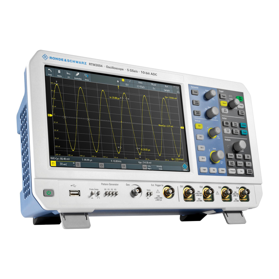
www.allice.de Allice Messtechnik GmbH ® Getting Started R&S RTM3000 Instrument Tour Action Condition Result [Standby] Switch [Standby] off. Power switch is on. Software shuts down. All instru- Yellow ment settings are saved, running data transfers and processes are interrupted (e.g., self-alignment). Instrument is in standby mode. - Page 25 www.allice.de Allice Messtechnik GmbH ® Getting Started R&S RTM3000 Instrument Tour Figure 2-1: Front panel of R&S RTM3000 with 4 input channels 1 = Display 2 = Horizontal and vertical setup controls 3 = Trigger settings, action and analysis controls 4 = Analog input channels (BNC) 5 = External trigger input 6 = Connectors for demo signal output...
- Page 26 www.allice.de Allice Messtechnik GmbH ® Getting Started R&S RTM3000 Instrument Tour BNC inputs (4 and 5) The R&S RTM3000 has two or four channel inputs (4) to connect the input signals. The external trigger input (5) is used to control the measurement by an external signal. The trigger level can be set from -5 V to 5 V.
- Page 27 www.allice.de Allice Messtechnik GmbH ® Getting Started R&S RTM3000 Instrument Tour 2.2.1.2 Other Connectors on the Front Panel [Demo] (6) The pins are intended for demonstration purposes. [Gen]: Function Generator (7) BNC output of the function generator (with option R&S RTM-B6). [Pattern Generator] (8) Connectors for the pattern generator P0, P1, P2, P3.
-
Page 28: Side View
www.allice.de Allice Messtechnik GmbH ® Getting Started R&S RTM3000 Instrument Tour 2.2.2 Side View Figure 2-2: Side view of R&S RTM3000 1 = Connectors for logic probe (Mixed Signal Option R&S RTM-B1) Logic probe The connectors for logic channels can be used if the Mixed Signal Option R&S RTM- B1 is installed. - Page 29 www.allice.de Allice Messtechnik GmbH ® Getting Started R&S RTM3000 Instrument Tour Figure 2-3: Rear panel view of R&S RTM3000 1 = Aux Out connector 2 = USB connector, type B 3 = LAN connector 4 = AC power supply connector and main power switch 5 = Kensington lock slot to secure the instrument against theft 6 = Loop for lock to secure the instrument against theft 7 = not used...
- Page 30 www.allice.de Allice Messtechnik GmbH ® Getting Started R&S RTM3000 Instrument Tour AC supply: mains connector and main power switch (4) The instrument supports a wide range power supply. It automatically adjusts to the cor- rect range for the applied voltage. There is no line voltage selector. The AC main power switch disconnects the instrument from the AC power line.
-
Page 31: Operating Basics
www.allice.de Allice Messtechnik GmbH ® Operating Basics R&S RTM3000 Display Overview 3 Operating Basics 3.1 Display Overview The touchscreen display of the instrument shows the waveforms and measurement results, and also information and everything that you need to control the instrument. Figure 3-1: Display of the R&S RTM3000 with 4 channels 1 = Toolbar 2 = Trigger source, main trigger parameter (here: slope for edge trigger), trigger level... -
Page 32: Selecting The Application
www.allice.de Allice Messtechnik GmbH ® Operating Basics R&S RTM3000 Using the Touchscreen 3.2 Selecting the Application The "Apps Selection" dialog provides fast access to all available applications. ► There are several ways to open the "Apps Selection" dialog: ● Press the [Apps Selection] key. - Page 33 www.allice.de Allice Messtechnik GmbH ® Operating Basics R&S RTM3000 Using the Touchscreen Figure 3-2: Open the main menu and select a menu item Figure 3-3: Switch on or off (left) and select a parameter value (right) ► To close the menu: User Manual 1335.9090.02 ─...
-
Page 34: Accessing Functionality Using Shortcuts
www.allice.de Allice Messtechnik GmbH ® Operating Basics R&S RTM3000 Using the Touchscreen Tap "Back", or tap into the diagram outside the menu. 3.3.2 Accessing Functionality Using Shortcuts The labels in information bar at the top of the display, the channel labels and also the results at the bottom provide shortcuts to the most important settings. -
Page 35: Using Gestures
www.allice.de Allice Messtechnik GmbH ® Operating Basics R&S RTM3000 Using the Touchscreen Figure 3-5: Enter numerical value and unit 3.3.4 Using Gestures Drag one finger Drag horizontally in the diagram to change the horizontal position of all waveforms. In frequency domain, the center frequency is changed. Drag vertically in the diagram to change the vertical position of the selected waveform. -
Page 36: Front Panel Keys
www.allice.de Allice Messtechnik GmbH ® Operating Basics R&S RTM3000 Front Panel Keys Spread or pinch two fingers in horizontal direction to change the horizontal scale of all waveforms. In frequency domain, the frequency span is changed. Swipe two fingers If the history option R&S RTM-K15 is installed, swipe two fingers in the diagram to scrolls through the history segments. -
Page 37: Analysis Controls
www.allice.de Allice Messtechnik GmbH ® Operating Basics R&S RTM3000 Front Panel Keys [Clear Screen] Deletes all waveforms, annotations and the measurement results of deleted wave- forms. All settings remain unchanged. Remote command: on page 585 DISPlay:CLEar[:SCReen] 3.4.2 Analysis Controls The controls in the [Analysis] functional block open various menus for signal analysis. [Navigation] The function of this universal rotary knob depends on the usage context: ●... -
Page 38: Using The Toolbar
www.allice.de Allice Messtechnik GmbH ® Operating Basics R&S RTM3000 Using the Toolbar Press the key to stop quick measurements. Note: Channels other than the selected one are switched off in quick measurement mode. When you activate quick measurements, cursor measurements are automati- cally deactivated. -
Page 39: Quick Access
www.allice.de Allice Messtechnik GmbH ® Operating Basics R&S RTM3000 Quick Access 2. Disable the functions that you do not need. 3. Tap the functions that you need. You can select maximum 8 functions. 4. Close the dialog box. 3.6 Quick Access If the measurement task requires to change the settings from different menus repeat- edly, you can use the "QuickAccess". -
Page 40: Menu History
www.allice.de Allice Messtechnik GmbH ® Operating Basics R&S RTM3000 Menu History c) Repeat steps a) and b) for each setting and function that you need for the mea- surement task. 3. To remove unwanted settings and functions: a) Tap the "Settings"... -
Page 41: Getting Help
www.allice.de Allice Messtechnik GmbH ® Operating Basics R&S RTM3000 Getting Help 3.8 Getting Help In most menus and dialogs, graphics explain the meaning of the selected setting. For further information, you can open the help, which provides functional description of selected setting. -
Page 42: Waveform Setup
www.allice.de Allice Messtechnik GmbH ® Waveform Setup R&S RTM3000 Connecting Probes and Displaying a Signal 4 Waveform Setup This chapter describes how to connect and set up probes, to adjust the horizontal and vertical settings, and to control the acquisition. 4.1 Connecting Probes and Displaying a Signal Risk of instrument damage Make sure to set the attenuation factor on the instrument according to the probe being... -
Page 43: Horizontal Setup
www.allice.de Allice Messtechnik GmbH ® Waveform Setup R&S RTM3000 Horizontal Setup 1 Ω resistor and a 10:1 probe is used, the V/A-value of the resistor is 1 V/A. The attenuation factor of the probe is 0.1, and the resulting current probe attenuation is 100 mV/A. - Page 44 www.allice.de Allice Messtechnik GmbH ® Waveform Setup R&S RTM3000 Horizontal Setup the horizontal acquisition window to the waveform section of interest, you can use the following parameters: ● The horizontal position defines the time distance of the trigger point (the zero point of the diagram) to the reference point.
-
Page 45: Horizontal Controls
www.allice.de Allice Messtechnik GmbH ® Waveform Setup R&S RTM3000 Horizontal Setup 4.2.1 HORIZONTAL Controls [Position] Changes the trigger position, the time distance from the trigger point to the reference point (trigger offset). The trigger point is the zero point of the diagram. Thus, you can set the trigger point even outside the diagram and analyze the signal some time before or after the trigger. -
Page 46: Shortcuts For Horizontal Settings
www.allice.de Allice Messtechnik GmbH ® Waveform Setup R&S RTM3000 Horizontal Setup [Horizontal] Opens the menu to configure horizontal scale, position, and reference point. The cur- rent scale and position is shown in the top information bar. If zoom is active, you can find also the zoom scale and zoom position in this menu. [Acquisition] Opens the "Acquisition"... -
Page 47: Vertical Setup
www.allice.de Allice Messtechnik GmbH ® Waveform Setup R&S RTM3000 Vertical Setup The reference point defines which part of the waveform is shown. By default, the refer- ence point is displayed in the center of the window, and you can move it to the left or right. -
Page 48: Vertical Controls
www.allice.de Allice Messtechnik GmbH ® Waveform Setup R&S RTM3000 Vertical Setup There are several ways to adjust vertical settings: ● Use the controls in the Vertical functional block of the front panel to select the channel, to scale the waveform, and to set the position. ●... - Page 49 www.allice.de Allice Messtechnik GmbH ® Waveform Setup R&S RTM3000 Vertical Setup [Offset/Position (upper knob)] The upper vertical knob adjusts the following, depending on the selected waveform: ● Offset or position of an analog channel (adjustable: main menu > "Vertical"). The visual effect is the same.
-
Page 50: Short Menu For Analog Channels
www.allice.de Allice Messtechnik GmbH ® Waveform Setup R&S RTM3000 Vertical Setup [Math] Displays the math waveforms with their last configuration. A math waveform is a wave- form that is calculated from the captured data. The second keypress opens the menu, where you can activate and configure math waveforms, and save and load equation sets. - Page 51 www.allice.de Allice Messtechnik GmbH ® Waveform Setup R&S RTM3000 Vertical Setup 1. To open the "Vertical" menu: a) Open the main menu. b) Select "Vertical". 2. Select the parameter that is assigned to the upper vertical knob: "Offset" or "Posi- tion".
- Page 52 www.allice.de Allice Messtechnik GmbH ® Waveform Setup R&S RTM3000 Vertical Setup Vert. Position Knob Selects the parameter to be changed with the [Offset/Position (upper knob)]: "Offset" or "Position". By default, position is set. [Preset] does not affect the assignment. Channel <n> Opens the channel menu.
- Page 53 www.allice.de Allice Messtechnik GmbH ® Waveform Setup R&S RTM3000 Vertical Setup To reduce noise, you can set a frequency limit. Higher frequencies are removed from the signal. Limited bandwidth is indicated by "B " in the waveform label. For analog applications, the highest signal frequency determines the required oscillo- scope bandwidth.
- Page 54 www.allice.de Allice Messtechnik GmbH ® Waveform Setup R&S RTM3000 Vertical Setup Position Moves the selected signal up or down in the diagram. While the offset sets a voltage, position is a graphical setting given in divisions. The visual effect is the same as for off- set.
-
Page 55: Threshold Settings
www.allice.de Allice Messtechnik GmbH ® Waveform Setup R&S RTM3000 Vertical Setup "Temperature" Display in temperature colors. Blue corresponds to rare occurrences of the samples, while white indicates frequent ones. "Rainbow" Display in rainbow colors. Blue corresponds to rare occurrences of the samples, while red indicates frequent ones. -
Page 56: Label Settings
www.allice.de Allice Messtechnik GmbH ® Waveform Setup R&S RTM3000 Vertical Setup Threshold Hysteresis Logic 0 Logic 1 Logic 0 The numerical values of "Small", "Medium", and "Large" hysteresis correspond to the vertical scale. Remote command: on page 436 CHANnel<m>:THReshold:HYSTeresis Find Threshold The instrument analyzes the channel and sets the threshold for digitization. -
Page 57: Probes
www.allice.de Allice Messtechnik GmbH ® Waveform Setup R&S RTM3000 Probes Edit Label Opens on-screen keypad to enter a label text. If you previously have selected a prede- fined label, it is already written in the entry line, and you can modify it. The maximum name length is 8 characters, and only ASCII characters provided on the on-screen keypad can be used. -
Page 58: Probe Settings For Probes With Bnc Connector
www.allice.de Allice Messtechnik GmbH ® Waveform Setup R&S RTM3000 Probes 4.4.2 Probe Settings for Probes with BNC Connector For passive probes, which are connected with a BNC connector, you set the probe attenuation and the unit, and you can start an adjustment procedure for the probe. All settings are channel-specific. -
Page 59: Probe Settings For Probes With Rohde & Schwarz Interface
www.allice.de Allice Messtechnik GmbH ® Waveform Setup R&S RTM3000 Probes 4.4.3 Probe Settings for Probes with Rohde & Schwarz Interface Probes with Rohde & Schwarz probe interface have an integrated data memory that contains identification data and individual probe correction parameters. The R&S RTM3000 can detect these probes and read out the data, for example, band- width, termination and attenuation. - Page 60 www.allice.de Allice Messtechnik GmbH ® Waveform Setup R&S RTM3000 Probes Copy to offset Sets the offset to the mean value of the ProbeMeter's DC measurement. Remote command: on page 442 PROBe<m>:SETup:ADVanced:PMToffset ® ProbeMeter Shows the measurement result of the integrated R&S ProbeMeter of active Rohde &...
- Page 61 www.allice.de Allice Messtechnik GmbH ® Waveform Setup R&S RTM3000 Probes Remote command: on page 438 PROBe<m>:SETup:MODE Info Shows general information on the connected probe, for example, type, serial number, and production date. Below, electrical characteristics are shown, like bandwidth, attenuation, input capacitance and impedance, voltage and DC offset range. Remote command: on page 440 PROBe<m>:SETup:NAME?
- Page 62 www.allice.de Allice Messtechnik GmbH ® Waveform Setup R&S RTM3000 Probes Figure 4-4: Probe settings of R&S RT-ZD20 with ProbeMeter measurement Offset Same as "Offset" in the "Vertical" menu, see "Offset" on page 53. Copy to offset Same as "Copy to offset" for active broadband single-ended probes, see "Copy to off- set"...
- Page 63 www.allice.de Allice Messtechnik GmbH ® Waveform Setup R&S RTM3000 Probes Current probes R&S RT-ZCxx The current probes R&S RT-ZCxx have BNC connectors. The setup is described in Chapter 4.4.2, "Probe Settings for Probes with BNC Connector", on page 58. Demag- netizing and zero adjustment is done on the probe, see the probe's User Manual for details.
- Page 64 www.allice.de Allice Messtechnik GmbH ® Waveform Setup R&S RTM3000 Probes Remote command: on page 442 PROBe<m>:SETup:DEGauss Info Same as for active single-ended probes, see "Info" on page 61. 4.4.3.4 High-Voltage Differential Probes Rohde & Schwarz high-voltage differential probes of the R&S RT-ZHD series have the same settings as active broadband differential probes, and additional range settings.
- Page 65 www.allice.de Allice Messtechnik GmbH ® Waveform Setup R&S RTM3000 Probes "Auto" The voltage range is set only at the oscilloscope by adjusting the ver- tical scale. "<High value>" Sets the higher voltage range of the connected probe. The selection list shows the value that is specified on the probe. "<Low value>"...
- Page 66 www.allice.de Allice Messtechnik GmbH ® Waveform Setup R&S RTM3000 Probes Figure 4-6: Probe settings of R&S RT-ZM30 with ProbeMeter measurement Offset Same as "Offset" in the "Vertical" menu, see "Offset" on page 53. Copy to offset Same as "Copy to offset" for active broadband single-ended probes, see "Copy to off- set"...
- Page 67 www.allice.de Allice Messtechnik GmbH ® Waveform Setup R&S RTM3000 Probes "DM" Differential mode input voltage (V ), the voltage between the positive and negative input terminal. "CM" Common mode input voltage (V ), the mean voltage between the positive and negative input terminal vs. ground. "P"...
-
Page 68: Acquisition Setup
www.allice.de Allice Messtechnik GmbH ® Waveform Setup R&S RTM3000 Acquisition Setup Offset Same as "Offset" in the "Vertical" menu, see "Offset" on page 53. Copy to offset Same as "Copy to offset" for active broadband single-ended probes, see "Copy to off- set"... -
Page 69: Shortcuts For Acquisition Settings
www.allice.de Allice Messtechnik GmbH ® Waveform Setup R&S RTM3000 Acquisition Setup 4.5.1 Shortcuts for Acquisition Settings To adjust the acquisition mode, and to perform a single acquisition, you can use the shortcuts on the top of the display. The labels show the current values. 1 = start or stop a continuous acquisition, or start a single acquisition if [Single] is active 2 = adjust the acquisition mode 3 = shows the current sample rate for information... - Page 70 www.allice.de Allice Messtechnik GmbH ® Waveform Setup R&S RTM3000 Acquisition Setup Remote command: on page 449 ACQuire:POINts:AUTomatic on page 450 ACQuire:POINts[:VALue] Acquire Mode Defines how the waveform is built from the captured samples. There are two general methods to build the waveform record: sample decimation and waveform arithmetic. Sample decimation reduces the data stream of the ADC to a stream of waveform points with lower sample rate and a less precise time resolution.
- Page 71 www.allice.de Allice Messtechnik GmbH ® Waveform Setup R&S RTM3000 Acquisition Setup "Envelope + Each acquisition is done in high resolution mode, and the minimum HR" and maximum values over some consecutive acquisitions build the envelope. Remote command: on page 451 CHANnel<m>:ARIThmetics on page 450 CHANnel<m>:TYPE...
- Page 72 www.allice.de Allice Messtechnik GmbH ® Waveform Setup R&S RTM3000 Acquisition Setup "Sin(x)/x" Two adjacent ADC sample points are connected by a sin(x)/x curve, and also the adjoining sample points are considered by this curve. The interpolated points are placed on the resulting curve. This inter- polation method is the default method.
-
Page 73: Trigger
www.allice.de Allice Messtechnik GmbH ® Trigger R&S RTM3000 5 Trigger Triggering means to capture the interesting part of the relevant waveforms. Choosing the right trigger type and configuring all trigger settings correctly allows you to detect various incidents in signals. A trigger occurs if the trigger conditions are fulfilled. -
Page 74: Trigger Controls
www.allice.de Allice Messtechnik GmbH ® Trigger R&S RTM3000 Trigger Controls 5.1 Trigger Controls The keys and the rotary knob in the Trigger functional block adjust the trigger and start or stop acquisition. The green LED above the [Levels] knob lights up when the instrument triggers. [Trigger] Opens the "Trigger"... -
Page 75: Shortcuts For Trigger Settings
www.allice.de Allice Messtechnik GmbH ® Trigger R&S RTM3000 Shortcuts for Trigger Settings Remote command: on page 457 TRIGger:A:LEVel<n>[:VALue] on page 457 TRIGger:A:FINDlevel [Force Trigger] Provokes an immediate single acquisition. Use this key if the acquisition is running in normal mode and no valid trigger occurs. Thus, you can confirm that a signal is availa- ble and use the waveform display to determine how to trigger on it. -
Page 76: General Trigger Settings
www.allice.de Allice Messtechnik GmbH ® Trigger R&S RTM3000 General Trigger Settings 1 = adjust the trigger source 2 = open the keypad to enter the value of the trigger level or threshold 3 = adjust slope or polarity 4 = adjust the trigger mode 5 = start or stop a continuous acquisition, or start a single acquisition if [Single] is active 6 = available settings depend on the trigger type 5.3 General Trigger Settings... - Page 77 www.allice.de Allice Messtechnik GmbH ® Trigger R&S RTM3000 General Trigger Settings "Norm" The instrument acquires a normal waveform only, if a trigger occurs, that is, if all trigger conditions are fulfilled. If no trigger occurs, no waveform is acquired and the last acquired waveform is displayed. If no waveform was captured before, nothing is displayed.
-
Page 78: Edge Trigger
www.allice.de Allice Messtechnik GmbH ® Trigger R&S RTM3000 Edge Trigger "Extern" Sets the external trigger input on the front panel as trigger source. Available for edge and video trigger. "B1, B2, B3 or Serial bus that is used for triggering on protocols. Only available, if B4"... - Page 79 www.allice.de Allice Messtechnik GmbH ® Trigger R&S RTM3000 Edge Trigger Slope..........................79 Trigger Level, Threshold....................79 Hysteresis........................80 Coupling........................80 Reject........................80 Noise Reject........................80 Slope Sets the edge direction for the trigger. You can trigger on: ● rising edge, that is a positive voltage change ●...
-
Page 80: Edge A/B Trigger
www.allice.de Allice Messtechnik GmbH ® Trigger R&S RTM3000 Edge A/B Trigger Hysteresis Sets a hysteresis range around the trigger level. Hysteresis avoids unwanted trigger events caused by noise oscillation around the trigger level. The automatic, small, medium, large hysteresis values depend on the vertical scale. Hysteresis is not available if "Source"... -
Page 81: Width Trigger
www.allice.de Allice Messtechnik GmbH ® Trigger R&S RTM3000 Width Trigger Trigger Setup Opens a dialog where you configure the trigger sequence. On the left, the first edge trigger (A) is defined as usual. On the right, a second edge trigger (B) is defined with the same parameters: source, level, edge, and hysteresis. - Page 82 www.allice.de Allice Messtechnik GmbH ® Trigger R&S RTM3000 Width Trigger You can use the width trigger, for example, to trigger on glitches. Figure 5-2: Pulse width is shorter (left) or longer (right) than a given duration (also known as glitch trigger) Figure 5-3: Pulse width is inside or outside an allowable time range 1 = Inside: min width <...
- Page 83 www.allice.de Allice Messtechnik GmbH ® Trigger R&S RTM3000 Width Trigger Polarity.......................... 83 Comparison........................83 Time t..........................84 Variation........................84 Time t1, Time t2......................84 Threshold........................84 Hysteresis........................84 Polarity Sets the polarity of the pulse. You can trigger on: ● positive going pulse, the width is defined from the rising to the falling slopes. ●...
-
Page 84: Video Trigger
www.allice.de Allice Messtechnik GmbH ® Trigger R&S RTM3000 Video Trigger "Inside"[, ]"Out- Triggers on pulses inside or outside a range specified with "Time t1" side" and "Time t2". This method is an alternative setting to the range definition with "Time t" and "Variation". The values are interdependent. "Variation" and "Time t"... - Page 85 www.allice.de Allice Messtechnik GmbH ® Trigger R&S RTM3000 Video Trigger First select the standard and the signal polarity, then decide to trigger on lines or fields and enter the specific settings. ► [Trigger] > "Trigger Type" = "Video" Figure 5-5: Video trigger menu Standard........................85 Signal..........................
-
Page 86: Pattern Trigger
www.allice.de Allice Messtechnik GmbH ® Trigger R&S RTM3000 Pattern Trigger Signal Selects the polarity of the signal. Note that the sync pulse has the opposite polarity. If the video modulation is positive, the sync pulses are negative. If the modulation is neg- ative, sync pulses are positive. - Page 87 www.allice.de Allice Messtechnik GmbH ® Trigger R&S RTM3000 Pattern Trigger ► [Trigger] > "Trigger Type" = "Pattern" > "Edit Pattern" Figure 5-7: Pattern trigger with logic editor Thresholds At the bottom of the "Logic Editor", you see the current threshold settings of all chan- nels.
- Page 88 www.allice.de Allice Messtechnik GmbH ® Trigger R&S RTM3000 Pattern Trigger Remote command: on page 463 TRIGger:A:PATTern:SOURce And | Or Sets the logical combination of the channel states. "AND" All defined states must be true. "OR" At least one of the defined states must be true. Remote command: on page 464 TRIGger:A:PATTern:FUNCtion...
-
Page 89: Runt Trigger
www.allice.de Allice Messtechnik GmbH ® Trigger R&S RTM3000 Runt Trigger Remote command: on page 464 TRIGger:A:PATTern:MODE on page 465 TRIGger:A:PATTern:WIDTh:RANGe on page 465 TRIGger:A:PATTern:WIDTh[:WIDTh] on page 465 TRIGger:A:PATTern:WIDTh:DELTa 5.9 Runt Trigger A runt is a pulse lower than normal in amplitude. The amplitude crosses the first threshold twice in succession without crossing the second one. -
Page 90: Rise Time Trigger
www.allice.de Allice Messtechnik GmbH ® Trigger R&S RTM3000 Rise Time Trigger Upper Level Sets the upper voltage threshold for runt detection. A negative runt crosses the upper level twice without crossing the lower level. Remote command: on page 466 TRIGger:A:LEVel<n>:RUNT:UPPer Lower Level Sets the lower voltage threshold for runt detection. - Page 91 www.allice.de Allice Messtechnik GmbH ® Trigger R&S RTM3000 Rise Time Trigger Polarity.......................... 91 Comparison........................91 Rise Time........................92 Variation........................92 Upper Level........................92 Lower Level........................92 Hysteresis........................92 Find Threshold......................92 Polarity Sets the edge, the transition time of which is to be analyzed: ●...
-
Page 92: Timeout Trigger
www.allice.de Allice Messtechnik GmbH ® Trigger R&S RTM3000 Timeout Trigger ± Varia- "Equal" Triggers on transition times inside the time range Rise Time tion. ± Varia- "Not equal" Triggers on transition times outside the time range Rise Time tion. Remote command: on page 468 TRIGger:A:RISetime:RANGe Rise Time... - Page 93 www.allice.de Allice Messtechnik GmbH ® Trigger R&S RTM3000 Timeout Trigger time Figure 5-8: Timeout trigger with range Stays High ► [Trigger] > "Trigger Type" = "Timeout" Figure 5-9: Timeout trigger menu Range Selects the relation of the signal level to the threshold: Stays High The signal level stays above the trigger level.
-
Page 94: Actions On Trigger
www.allice.de Allice Messtechnik GmbH ® Trigger R&S RTM3000 Actions on Trigger Hysteresis Hysteresis of the trigger source channel, see "Hysteresis" on page 55. Remote command: on page 436 CHANnel<m>:THReshold:HYSTeresis 5.12 Actions on Trigger A trigger event can be used to initiate one or several actions. All available actions can be initiated at the same time, and for all trigger types. - Page 95 www.allice.de Allice Messtechnik GmbH ® Trigger R&S RTM3000 Actions on Trigger Actions on Trigger Activates the selected actions on trigger event. Remote command: on page 470 TRIGger:EVENt[:ENABle] Configuration Opens a menu to select the actions that are initiated on trigger event. Pulse Generates a pulse on the Aux Out connector on trigger event.
- Page 96 www.allice.de Allice Messtechnik GmbH ® Trigger R&S RTM3000 Actions on Trigger References Saves reference waveforms of all active channels, and activates the references. This action works only with single acquisition. The channels are assigned to the references: C1 to R1, C2 to R2 and so on. If a chan- nel is off, the assigned reference is also not active.
-
Page 97: Waveform Analysis
www.allice.de Allice Messtechnik GmbH ® Waveform Analysis R&S RTM3000 Zoom 6 Waveform Analysis ● Zoom........................97 ● Mathematics......................101 ● Reference Waveforms................... 111 ● History and Segmented Memory (Option R&S RTM-K15)........116 ● Search........................125 6.1 Zoom The zoom magnifies a part of the waveform to view more details. The zoom is applied to all active analog and digital channels and math waveforms. - Page 98 www.allice.de Allice Messtechnik GmbH ® Waveform Analysis R&S RTM3000 Zoom Figure 6-1: Display of horizontal zoom: zoom in bottom window, normal waveform in upper window = Tap to activate zoom settings = Tap to activate normal waveform settings 3 (blue) = Horizontal zoom scale and width of the zoom area 4 (red) = Horizontal zoom position = Acquire mode, can be set in zoom window or in the upper status bar = Horizontal scale and position of the normal waveform...
-
Page 99: Modifying The Zoom
www.allice.de Allice Messtechnik GmbH ® Waveform Analysis R&S RTM3000 Zoom Figure 6-2: Display of vertical zoom 6.1.2 Modifying the Zoom There are several ways to adjust the zoom: ● Use finger gestures on the screen. ● Use the [Scale] and [Position] knobs. ●... -
Page 100: Zoom Settings
www.allice.de Allice Messtechnik GmbH ® Waveform Analysis R&S RTM3000 Zoom Drag the zoom area on the original waveform in the upper window. To adjust the zoom using the horizontal rotary knobs 1. To set the focus to the zoom window (lower window), tap in the zoom window. 2. -
Page 101: Mathematics
www.allice.de Allice Messtechnik GmbH ® Waveform Analysis R&S RTM3000 Mathematics Remote command: on page 472 TIMebase:ZOOM:SCALe Zoom Position Defines the distance of the trigger point to the reference point in the zoom window. The value determines the position of the zoom area in the upper window. "Zoom Position"... -
Page 102: Configuring Math Waveforms
www.allice.de Allice Messtechnik GmbH ® Waveform Analysis R&S RTM3000 Mathematics 6.2.2 Configuring Math Waveforms 1. Press the [Math] key. The math waveforms are activated, using the latest settings. 2. Press the [Math] key again. The "Mathematics" menu and the "Equation Set Editor" are shown. 3. -
Page 103: Mathematic Functions
www.allice.de Allice Messtechnik GmbH ® Waveform Analysis R&S RTM3000 Mathematics – Waveform color Remote commands: ● on page 473 CALCulate:MATH<m>:STATe ● on page 475 CALCulate:MATH<m>:POSition ● on page 476 CALCulate:MATH<m>:SCALe ● on page 476 CALCulate:MATH<m>:WCOLor ● Waveform transfer: see Chapter 16.9.1.3, "Math Waveforms", on page 568 ●... - Page 104 www.allice.de Allice Messtechnik GmbH ® Waveform Analysis R&S RTM3000 Mathematics Addition Source1 + Source2 Adds the values of 2 sources (channel or math waveform, or con- stant). Subtraction Source1 - Source2 Subtracts the second source from the first source. Multiplication Source1 * Source2 Multiplies the two sources.
-
Page 105: Filters
www.allice.de Allice Messtechnik GmbH ® Waveform Analysis R&S RTM3000 Mathematics Common Log. log(Source) Calculates the logarithm to the basis 10 of the source. Note that the logarithm of a negative number is undefined and the result is clipped. Natural Log. ln(Source) Calculates the logarithm to the basis e (Euler number) of the source. -
Page 106: Tracks
www.allice.de Allice Messtechnik GmbH ® Waveform Analysis R&S RTM3000 Mathematics Table 6-1: Available math filters Low pass LP(Source,BW) Calculates a low-pass filtered waveform of the source waveform using 2nd order IIR. The cut-off frequency BW is set as a const value. Signal components with fre- quencies higher than the cut-off frequency are attenuated significantly. - Page 107 www.allice.de Allice Messtechnik GmbH ® Waveform Analysis R&S RTM3000 Mathematics Track frequency (bipolar) TFREQB(Source) in Hz Tracks the frequency values of a bipolar source waveform. Track pulse width TPW(Source) in s Tracks the pulse width of the source waveform. For a PWM source signal, the result is the demodulated waveform.
- Page 108 www.allice.de Allice Messtechnik GmbH ® Waveform Analysis R&S RTM3000 Mathematics Figure 6-6: Bipolar PWM waveform with duty cycle track M1 in green and period track M2 in blue Figure 6-7: Unipolar PDM waveform with pulse width track M1 in green and period track M2 in blue User Manual 1335.9090.02 ─...
- Page 109 www.allice.de Allice Messtechnik GmbH ® Waveform Analysis R&S RTM3000 Mathematics Figure 6-8: Bipolar PDM signal with pulse width track M1 in green and period track M2 in blue. For PDM waveforms, pulse width and period are synchronous. 6.2.6.1 Settings for Tracks The determination of track values requires one threshold for unipolar PWM signals, and two thresholds for bipolar PWM signals.
- Page 110 www.allice.de Allice Messtechnik GmbH ® Waveform Analysis R&S RTM3000 Mathematics Hyst Sets the hysteresis for correct edge detection. Remote command: on page 477 CALCulate:MATH<m>:TRACk:THReshold:HYSTeresis Edge Sets the rising or falling edge as a reference for each measurement. The setting helps to determine values in terms of the power stage switching state.
-
Page 111: Saving And Loading Formularies
www.allice.de Allice Messtechnik GmbH ® Waveform Analysis R&S RTM3000 Reference Waveforms 3. Select the signal. 4. Connect the input channels. The required connection is shown in the upper left cor- ner of the display. Signal Connect source... With input channel... PWM Unipolar "Gen"... -
Page 112: Using References
www.allice.de Allice Messtechnik GmbH ® Waveform Analysis R&S RTM3000 Reference Waveforms Reference waveforms are waveform data stored in the internal reference storages. Four reference waveforms are available and can be displayed: R1 to R4. The display of a reference waveform is independent from the display of the source waveform;... -
Page 113: Settings For Reference Waveforms
www.allice.de Allice Messtechnik GmbH ® Waveform Analysis R&S RTM3000 Reference Waveforms The new reference waveform is created on top of its origin, and it has the focus. 3. To change the scaling and position, use the horizontal and vertical [Position] and [Scale] knobs. - Page 114 www.allice.de Allice Messtechnik GmbH ® Waveform Analysis R&S RTM3000 Reference Waveforms a) Tap the menu icon in the lower right corner of the screen. b) Scroll down. Select "References". Source......................... 114 Reference........................114 Copy..........................115 State..........................115 Load Reference......................115 Load Setup........................115 Save Reference......................115 Waveform...
- Page 115 www.allice.de Allice Messtechnik GmbH ® Waveform Analysis R&S RTM3000 Reference Waveforms Copy Copies the "Source" waveform to the selected reference waveform. The reference waveform is kept until you update it or load another waveform to the reference. Remote command: on page 479 REFCurve<m>:UPDate State Activates the reference waveform and displays it.
-
Page 116: History And Segmented Memory (Option R&S Rtm-K15)
www.allice.de Allice Messtechnik GmbH ® Waveform Analysis R&S RTM3000 History and Segmented Memory (Option R&S RTM-K15) The color scales are described in "Waveform Color" on page 54. Remote command: on page 481 REFCurve<m>:WCOLor Label Opens a menu to specify user-defined text labels for the individual reference wave- forms. - Page 117 www.allice.de Allice Messtechnik GmbH ® Waveform Analysis R&S RTM3000 History and Segmented Memory (Option R&S RTM-K15) the displayed waveform and also the data of the waveforms that have been captured before. Each stored waveform is called a segment. The record length of the segments can be defined.
-
Page 118: Activating The History
www.allice.de Allice Messtechnik GmbH ® Waveform Analysis R&S RTM3000 History and Segmented Memory (Option R&S RTM-K15) 6.4.2 Activating the History To activate the history 1. Tap the "Menu" icon. 2. Select "History". 3. Enable "Show History". The segment table and the history player are shown. 4. - Page 119 www.allice.de Allice Messtechnik GmbH ® Waveform Analysis R&S RTM3000 History and Segmented Memory (Option R&S RTM-K15) The "History" menu has the following settings: Auto Defines how the record length and number of segments are set: automatically by the instrument, or by setting the record length or number of segments manually. In automatic mode, you can adjust the record length in the "Acquisition"...
-
Page 120: Segment Table And History Player
www.allice.de Allice Messtechnik GmbH ® Waveform Analysis R&S RTM3000 History and Segmented Memory (Option R&S RTM-K15) Fast segmentation takes effect for [Single] acquisitions if "Nx Single" > 1. See also: Chapter 6.4.1, "Segmented Memory", on page 116 Remote command: on page 499 ACQuire:SEGMented:STATe Show History Enables or disables the history. - Page 121 www.allice.de Allice Messtechnik GmbH ® Waveform Analysis R&S RTM3000 History and Segmented Memory (Option R&S RTM-K15) 7. To access a particular segment, you can: ● Tap the segment in the segment table. ● Drag the slider until the required segment number is shown. ●...
-
Page 122: Exporting History Data
www.allice.de Allice Messtechnik GmbH ® Waveform Analysis R&S RTM3000 History and Segmented Memory (Option R&S RTM-K15) Repeat If selected, the playback of the selected history segments repeats automatically. Remote command: ...:HISTory:REPLay Speed Sets the speed of the history playback: automatic, slow, middle, or fast. Remote command: ...:HISTory:PLAYer:SPEed Number... - Page 123 www.allice.de Allice Messtechnik GmbH ® Waveform Analysis R&S RTM3000 History and Segmented Memory (Option R&S RTM-K15) To save the waveform history segments 1. Connect a USB flash drive to the instrument. 2. Press the [Save Load] key. 3. Select "Waveforms" in the menu. 4.
- Page 124 www.allice.de Allice Messtechnik GmbH ® Waveform Analysis R&S RTM3000 History and Segmented Memory (Option R&S RTM-K15) The file is saved immediately, and the window is closed. 6.4.5.2 File Organization and Content The segment table and history segments are saved to CSV files. Segment table The segment table file contains all information that is shown in the table, and also all timestamps: relative time, time to previous, and absolute time.
-
Page 125: Search
www.allice.de Allice Messtechnik GmbH ® Waveform Analysis R&S RTM3000 Search Figure 6-12: Content of a history segment file, two channels are saved In addition to the data files, an index file is written. The index file delivers information on the files and the segments. For each segment, the segment index, save date and time, and the filename is listed. - Page 126 www.allice.de Allice Messtechnik GmbH ® Waveform Analysis R&S RTM3000 Search The found events and the search conditions are shown in the result table at the bottom of the display. The table shows the following result values: result number, time value, and optional value depending on the search type (voltage, width).
- Page 127 www.allice.de Allice Messtechnik GmbH ® Waveform Analysis R&S RTM3000 Search 3. In the "Search" menu, select "Track event". The selected event is moved to the reference point. If you select another event, it is shown at the same position. To save search results 1.
-
Page 128: General Search Settings
www.allice.de Allice Messtechnik GmbH ® Waveform Analysis R&S RTM3000 Search 5. Tap "Save". The data is saved to a CSV file. 6.5.2 General Search Settings General search settings are independent of the search type. They are described in the current section. The specific settings for individual search types are described in the following sections. - Page 129 www.allice.de Allice Messtechnik GmbH ® Waveform Analysis R&S RTM3000 Search "Rise/Fall time" The rise or fall time search finds slopes with an exact rise or fall time, or rise/fall times shorter or longer than a given limit, or rise/fall times inside or outside a given time range.
-
Page 130: Edge Search
www.allice.de Allice Messtechnik GmbH ® Waveform Analysis R&S RTM3000 Search Save Opens a dialog box to save the search results. The file format is CSV. Remote command: on page 497 EXPort:SEARch:NAME on page 497 EXPort:SEARch:SAVE 6.5.3 Edge Search Similar to the edge trigger, an edge search result is found when the waveform passes the given level in the specified direction. -
Page 131: Width Search
www.allice.de Allice Messtechnik GmbH ® Waveform Analysis R&S RTM3000 Search Find Threshold Analyzes the signal, sets the level to 50% of the signal amplitude, and also sets the hysteresis. 6.5.4 Width Search The width search finds pulses with an exact pulse width, or pulses shorter or longer than a given time, or pulses inside or outside the allowable time range. -
Page 132: Peak Search
www.allice.de Allice Messtechnik GmbH ® Waveform Analysis R&S RTM3000 Search Remote command: on page 485 SEARch:TRIGger:WIDTh:LEVel:DELTa Comparison Sets the condition how the measured pulse width is compared with the given limits. The comparison works like the comparison of the width trigger, see Chapter 5.6, "Width Trigger", on page 81. -
Page 133: Rise/Fall Time Search
www.allice.de Allice Messtechnik GmbH ® Waveform Analysis R&S RTM3000 Search 6.5.6 Rise/Fall Time Search The rise or fall time search finds slopes with an exact rise or fall time, or rise/fall times shorter or longer than a given limit, or rise/fall times inside or outside the allowable time range. -
Page 134: Runt Setup
www.allice.de Allice Messtechnik GmbH ® Waveform Analysis R&S RTM3000 Search "Equal" Finds rise/fall times equal to the reference "Rise/Fall Time" if "Varia- tion" Δt = 0. If "Variation" ≠ 0, the setting finds rise/fall times within the range time ± Δt. "Not equal"... - Page 135 www.allice.de Allice Messtechnik GmbH ® Waveform Analysis R&S RTM3000 Search Polarity Indicates the polarity of the pulse to be searched for. Remote command: on page 488 SEARch:TRIGger:RUNT:POLarity Upper Level Sets the upper voltage threshold for runt detection. A negative runt crosses the upper level twice without crossing the lower level.
-
Page 136: Data2Clock
www.allice.de Allice Messtechnik GmbH ® Waveform Analysis R&S RTM3000 Search Variation Sets a range Δt to the reference "Width" if comparison is set to "Equal" or "Not equal". The instrument finds pulses inside or outside the range width ± Δt. Remote command: on page 489 SEARch:TRIGger:RUNT:DELTa... -
Page 137: Pattern Search
www.allice.de Allice Messtechnik GmbH ® Waveform Analysis R&S RTM3000 Search Remote command: on page 483 SEARch:SOURce Level Set the voltage levels for clock and data signals. The crossing of clock level and clock edge defines the start point for setup and hold time. The data level defines the thresh- old for data transition. - Page 138 www.allice.de Allice Messtechnik GmbH ® Waveform Analysis R&S RTM3000 Search pattern results is compared with a specified time range. Thus you can find state transi- tions inside or outside this time range. ► Select [Search] > "Search Type" = "Pattern" > "Setup". Threshold, Hysteresis Sets the search threshold value for each analog channel.
-
Page 139: Window Search
www.allice.de Allice Messtechnik GmbH ® Waveform Analysis R&S RTM3000 Search "AND" The required states of all channels must appear in the input signal at the same time. "OR" At least one of the channels must have the required state. "NAND" "Not and"... - Page 140 www.allice.de Allice Messtechnik GmbH ® Waveform Analysis R&S RTM3000 Search Condition Selects how the signal runs in relation to the window. Additionallz, various time limita- tions can be defined with "Comparison" for most window conditions. "Enter" The signal crosses the upper or lower level and thus enters the win- dow made up of these two levels.
- Page 141 www.allice.de Allice Messtechnik GmbH ® Waveform Analysis R&S RTM3000 Search Remote command: on page 494 SEARch:TRIGger:WINDow:TIMerange User Manual 1335.9090.02 ─ 08...
-
Page 142: Measurements
www.allice.de Allice Messtechnik GmbH ® Measurements R&S RTM3000 Quick Measurements 7 Measurements 7.1 Quick Measurements Quick measurement performs a set of automatic measurements on the selected input channel. The measurements cannot be configured. The results are displayed directly at the waveform (WF) or in the bottom result line (L) and are updated continuously. If the instrument detects a period in the signal, the quick measurement measures the first cycle and displays the results. -
Page 143: Automatic Measurements
www.allice.de Allice Messtechnik GmbH ® Measurements R&S RTM3000 Automatic Measurements Quick measurement is not available on math and reference waveforms. Channels other than the selected one are switched off in quick measurement mode. When quick measurement is active, cursor measurements are not possible, but you can use auto- matic measurements in parallel. - Page 144 www.allice.de Allice Messtechnik GmbH ® Measurements R&S RTM3000 Automatic Measurements Figure 7-1: Results of four active measurements Measurement errors are indicated as follows: A result cannot be determined. Adjust the horizontal and vertical settings if the instrument cannot measure. "clipping+" or "clipping-" The measurement result is outside the measurement range and clipping occurs.
- Page 145 www.allice.de Allice Messtechnik GmbH ® Measurements R&S RTM3000 Automatic Measurements Figure 7-2: Statistic results of four active measurements 1. To delete all measurement results, and to restart statistical evaluation, tap the "Reset" button. 2. To write statistic and measurement results to CSV file, tap the "Save" button. You can save the statistic results to CSV file for further evaluation.
-
Page 146: Measurement Types
www.allice.de Allice Messtechnik GmbH ® Measurements R&S RTM3000 Automatic Measurements Figure 7-3: Exported statistic results, converted to columns with comma delimiter 7.2.2 Measurement Types The R&S RTM3000 provides many measurement types to measure time and ampli- tude characteristics, and to count pulses and edges. User Manual 1335.9090.02 ─... - Page 147 www.allice.de Allice Messtechnik GmbH ® Measurements R&S RTM3000 Automatic Measurements 7.2.2.1 Horizontal Measurements (Time) Meas. type Symbol Description Graphic / formula Frequency Frequency of the signal, reciprocal value of the measured f = 1 / T first period. in Hz Period Time of the first period, measured on the middle reference level.
- Page 148 www.allice.de Allice Messtechnik GmbH ® Measurements R&S RTM3000 Automatic Measurements Meas. type Symbol Description Graphic / formula Delay Time difference between two slopes of the same or different waveforms, measured on the middle reference level. The in s settings of slope selection are described in Chapter 7.2.4, "Delay Setup",...
- Page 149 www.allice.de Allice Messtechnik GmbH ® Measurements R&S RTM3000 Automatic Measurements Meas. type Symbol Description Graphic / formula Mean Cycle MeanCyc Mean value of the left-most signal period. in V RMS Cycle RMS-Cyc RMS (root mean square) value of the voltage of the left- most signal period.
-
Page 150: Settings For Automatic Measurements
www.allice.de Allice Messtechnik GmbH ® Measurements R&S RTM3000 Automatic Measurements Meas. type Symbol Description Graphic / formula σ-Std. Dev. Cycle σ-Cyc Standard deviation of one cycle, usually of the first, left-most signal period. σ Crest Factor Crest The crest factor is also known as peak-to-average ratio. It is Crest ... - Page 151 www.allice.de Allice Messtechnik GmbH ® Measurements R&S RTM3000 Automatic Measurements In the measurement menu, you can configure up to 8 parallel measurements (also called measurement places). Available measurement types depend on the type of the selected waveform. Meas. Place Selects one of the four available measurement places to be configured or activated. Measure <n>...
- Page 152 www.allice.de Allice Messtechnik GmbH ® Measurements R&S RTM3000 Automatic Measurements If the waveform is not active, it is activated automatically when selected as measure- ment source. Remote command: on page 512 MEASurement<m>:SOURce Measure Source, Measure Source 2 Set the source waveforms for delay and phase measurement, where two sources are required.
-
Page 153: Delay Setup
www.allice.de Allice Messtechnik GmbH ® Measurements R&S RTM3000 Automatic Measurements Set the lower and upper reference levels for rise and fall time measurements. Sets also the middle reference level used for phase and delay measurements. The levels are defined as percentages of the high signal level. The settings are valid for all measure- ment places. - Page 154 www.allice.de Allice Messtechnik GmbH ® Measurements R&S RTM3000 Automatic Measurements Figure 7-4: Left: menu for delay measurement, right: menu for delay to trigger measurement Slope Selects the rising or falling edge for the indicated source. Remote command: on page 513 MEASurement<m>:DELay:SLOPe Mode for Measure Source, delay measurement Defines the first edge for the delay measurement.
-
Page 155: Cursor Measurements
www.allice.de Allice Messtechnik GmbH ® Measurements R&S RTM3000 Cursor Measurements Remote command: on page 513 MEASurement<m>:DELay:DIRection Display Results Shows the selected edge or edges on the waveform. The markers show the edge, the measured point on the edge, and the direction in which the edge is detected. The picture shows the delay measurement between the leftmost rising edge of Ch1 ("Measure Source") and the leftmost falling edge of Ch2 ("Measure Source 2"). - Page 156 www.allice.de Allice Messtechnik GmbH ® Measurements R&S RTM3000 Cursor Measurements Figure 7-5: Cursor measurement with vertical and horizontal cursors and Set To Trace Results = below the grid Cursor lines 1, 2, 3 = no focus Cursor line 4 = has focus, can be moved by turning the [Navigation] knob To configure cursor measurements 1.
-
Page 157: Cursor Settings
www.allice.de Allice Messtechnik GmbH ® Measurements R&S RTM3000 Cursor Measurements The keypad opens, and you can enter an exact value. 7.3.1 Cursor Settings ► To open the "Cursor" menu: a) Tap the "Menu" icon in the lower right corner of the screen. b) Scroll down. - Page 158 www.allice.de Allice Messtechnik GmbH ® Measurements R&S RTM3000 Cursor Measurements "Vertical" Sets two vertical cursor lines and measures the time from the trigger point to each cursor line, the time between the cursor lines and the frequency calculated from that time. Results: t1, t2, Δt, 1/Δt (for FFT measurements: frequencies) "Vertical &...
- Page 159 www.allice.de Allice Messtechnik GmbH ® Measurements R&S RTM3000 Cursor Measurements Figure 7-7: Cursor on one source Figure 7-8: Cursor on two sources. Sources are indicated with the measurement results. Remote command: on page 526 CURSor<m>:USSOURce on page 526 CURSor<m>:SSOURce Track Scaling If enabled, the cursor lines are adjusted when the vertical or horizontal scales are changed.
- Page 160 www.allice.de Allice Messtechnik GmbH ® Measurements R&S RTM3000 Cursor Measurements Coupling If enabled, the cursors lines are coupled and moved together. Press the [Navigation] key to select whether both cursors or one cursor is moved. If coupling is disabled, pressing the [Navigation] key toggles the single cursor lines. Remote command: on page 527 CURSor<m>:XCOupling...
-
Page 161: Applications
www.allice.de Allice Messtechnik GmbH ® Applications R&S RTM3000 Mask Testing 8 Applications All available applications are provided in the "Apps Selection" dialog. ► To select an application, press the [Apps Selection] key. See also: Chapter 3.2, "Selecting the Application", on page 32. Applications are grouped on several tabs: ●... -
Page 162: Using Masks
www.allice.de Allice Messtechnik GmbH ® Applications R&S RTM3000 Mask Testing The mask is displayed in the color used for reference waveforms. Once a mask has been defined, the copied envelope is kept in the instrument until the next mask is defined or loaded. If you need more than one mask, you can save the mask to internal storage and load it at a later time. - Page 163 www.allice.de Allice Messtechnik GmbH ® Applications R&S RTM3000 Mask Testing To create and set up a mask You create a mask based on a channel waveform, then optimize it by changing its posi- tion and proportions, and save it. 1. Select and adjust the channel waveform that you want to use as basis for the mask.
- Page 164 www.allice.de Allice Messtechnik GmbH ® Applications R&S RTM3000 Mask Testing 6. To save the mask for later use, tap "Save". To load a mask 1. Press the [Apps Selection] key. 2. Tap "Mask". 3. Tap "Load". 4. Select the mask file. 5.
-
Page 165: Mask Window
www.allice.de Allice Messtechnik GmbH ® Applications R&S RTM3000 Mask Testing 6. Tap "Reset" to delete the results. 7. To finish the test, tap "Stop". 8.1.3 Mask Window The mask window provides the most important function to set up a mask, and to run the test. -
Page 166: Mask Menu
www.allice.de Allice Messtechnik GmbH ® Applications R&S RTM3000 Mask Testing Size+, Size- Enlarges or decreases the mask in x- and y-direction. Save, Load Saves the created mask to file, or loads a previously saved mask. The file format is MSK. Remote command: on page 531 MASK:SAVE... - Page 167 www.allice.de Allice Messtechnik GmbH ® Applications R&S RTM3000 Mask Testing Test Performs a mask test for the selected signal, i.e. the signal amplitudes are compared with the specified mask. If the amplitude exceeds the limits of the mask, a violation is detected.
- Page 168 www.allice.de Allice Messtechnik GmbH ® Applications R&S RTM3000 Mask Testing Width X Changes the width of the mask in horizontal direction. The specified factor in divisions is added to the positive x-values and subtracted from the negative x-values of the mask limits in relation to the mask center.
-
Page 169: Fft Analysis
www.allice.de Allice Messtechnik GmbH ® Applications R&S RTM3000 FFT Analysis on page 532 MASK:ACTion:SCRSave:EVENt:MODE on page 532 MASK:ACTion:WFMSave:EVENt:MODE Capture Segments Selects whether all acquisitions are stored in segments, or only failed acquisition. You can use the hostiry to analyze the segments. Only available with history option R&S RTM-K15. - Page 170 www.allice.de Allice Messtechnik GmbH ® Applications R&S RTM3000 FFT Analysis 1 = Enable FFT 2 = Signal vs. time display 3 = FFT parameters 4 = Spectrum, result of the FFT analysis 5 = FFT label with vertical scale (range per division). Color indicates the source waveform of FFT calcula- tion.
-
Page 171: Performing Fft Analysis
www.allice.de Allice Messtechnik GmbH ® Applications R&S RTM3000 FFT Analysis Vertical position and size of the FFT waveform To set the position and the vertical scaling, select the FFT window and use the vertical [Scale] and [Offset/Position] knobs. Remote commands: ●... - Page 172 www.allice.de Allice Messtechnik GmbH ® Applications R&S RTM3000 FFT Analysis 8.2.3.1 Short Menu for FFT Frequently used settings are available in the short menu. You can select the waveform type, set full span, open the comprehensive menu and disable the FFT analysis. ►...
- Page 173 www.allice.de Allice Messtechnik GmbH ® Applications R&S RTM3000 FFT Analysis Remote command: on page 539 SPECtrum:FREQuency:STOP Center Defines the frequency in the center of the displayed span. The instrument adjusts the start and stop frequencies. To set the center frequency, you can also use the horizontal [Position] knob if the focus is on the frequency window.
- Page 174 www.allice.de Allice Messtechnik GmbH ® Applications R&S RTM3000 FFT Analysis 8.2.3.3 FFT Menu ► Press the [FFT] key. If the menu does not open, tap twice: Once to enable FFT, and next to open the menu. Source Selects the channel for which the captured data is analyzed with FFT. You can select one of the active input channels, math or reference waveforms.
- Page 175 www.allice.de Allice Messtechnik GmbH ® Applications R&S RTM3000 FFT Analysis "Blackman" The Blackman window is bell shaped and has the steepest fall in its wave shape of all other available functions. Its value is zero at both borders of the measuring interval. In the Blackman window, the ampli- tudes can be measured very precisely.
- Page 176 www.allice.de Allice Messtechnik GmbH ® Applications R&S RTM3000 FFT Analysis "Spectrum" The current value for each frequency is displayed. "Min Hold" The minimum value for each frequency over all FFTs is displayed. Using the "Min Hold" waveform type is a good way to highlight signals within noise or suppress intermittent signals.
-
Page 177: Spectrum Analysis And Spectrogram (Option R&S Rtm-K18)
www.allice.de Allice Messtechnik GmbH ® Applications R&S RTM3000 Spectrum Analysis and Spectrogram (Option R&S RTM-K18) "dBV" Logarithmic scaling; related to 1 Veff. Logarithmic scaling; related to 1 μVeff. "dBμV" "Veff" Linear scaling; displays the RMS value of the voltage. Remote command: on page 537 SPECtrum:FREQuency:MAGNitude:SCALe 8.3 Spectrum Analysis and Spectrogram (Option... - Page 178 www.allice.de Allice Messtechnik GmbH ® Applications R&S RTM3000 Spectrum Analysis and Spectrogram (Option R&S RTM-K18) Spectogram Enables the spectrogram. For details, see Chapter 8.3.2, "Spectrogram", on page 179. Remote command: on page 551 SPECtrum:DIAGram:SPECtrogram[:ENABle] Automatic RBW If enabled, the instrument sets an appropriate value for the resolution bandwidth. If dis- abled, you can set a manual value, see "RBW"...
-
Page 179: Spectrogram
www.allice.de Allice Messtechnik GmbH ® Applications R&S RTM3000 Spectrum Analysis and Spectrogram (Option R&S RTM-K18) Display Opens a menu to set up the display of the spectrum and the spectrogram. For details, see Chapter 8.3.4, "Display Settings for Spectrum and Spectrogram", on page 186. -
Page 180: Peak List And Markers
www.allice.de Allice Messtechnik GmbH ® Applications R&S RTM3000 Spectrum Analysis and Spectrogram (Option R&S RTM-K18) = Maximum level for color scale (setting) = Display of color scale = Minimum level for color scale (setting) = Range (information) 5, 6, 7 = Positions of the time cursors in the spectrogram, and their time difference Time cursors When acquisition is stopped, you can set two time cursors in the spectrogram. - Page 181 www.allice.de Allice Messtechnik GmbH ® Applications R&S RTM3000 Spectrum Analysis and Spectrogram (Option R&S RTM-K18) listed in the peak list. In addition, you can define a reference marker and get the peak results as delta values to the values of the reference marker. ►...
- Page 182 www.allice.de Allice Messtechnik GmbH ® Applications R&S RTM3000 Spectrum Analysis and Spectrogram (Option R&S RTM-K18) 8.3.3.1 Marker Menu Access: "FFT" menu > enable "Peak List" > "Marker" Source Defines the waveform type that is searched for peaks. Remote command: on page 544 SPECtrum:MARKer:SOURce Peak Setup Chapter 8.3.3.2, "Peak...
- Page 183 www.allice.de Allice Messtechnik GmbH ® Applications R&S RTM3000 Spectrum Analysis and Spectrogram (Option R&S RTM-K18) Min. Level Defines the minimum absolute level for peak detection. Only peaks that exceed the minimum level are detected, listed in the "Peak List", and marked in the spectrum dia- gram.
- Page 184 www.allice.de Allice Messtechnik GmbH ® Applications R&S RTM3000 Spectrum Analysis and Spectrogram (Option R&S RTM-K18) Remote command: on page 545 SPECtrum:MARKer:SETup:DISTance 8.3.3.3 R-Marker Settings Access: "FFT" menu > enable "Peak List" > "Marker" > "R-Marker" You can define a reference marker and get the peak results as delta values to the val- ues of the reference marker.
- Page 185 www.allice.de Allice Messtechnik GmbH ® Applications R&S RTM3000 Spectrum Analysis and Spectrogram (Option R&S RTM-K18) Remote command: on page 546 SPECtrum:MARKer:REFerence:SETup:FREQuency Span Defines frequency range around the center frequency if "R-Marker" = "Range". Remote command: on page 546 SPECtrum:MARKer:REFerence:SETup:SPAN Center to Screen Sets the center frequency to the center of the display.
-
Page 186: Display Settings For Spectrum And Spectrogram
www.allice.de Allice Messtechnik GmbH ® Applications R&S RTM3000 Spectrum Analysis and Spectrogram (Option R&S RTM-K18) Remote command: on page 547 SPECtrum:MARKer:RMODe Set R-Marker to Center of Screen Sets the reference marker to the center of the display. 8.3.4 Display Settings for Spectrum and Spectrogram You can change the color scale of the spectrogram and of the spectrum, and the level limits of the spectrogram. -
Page 187: Spectrum Analysis And Spectrogram (Option R&S Rtm-K37)
www.allice.de Allice Messtechnik GmbH ® Applications R&S RTM3000 Spectrum Analysis and Spectrogram (Option R&S RTM-K37) "Monochrome" The waveform is displayed in monochrome colors, which depend on the color of the selected source channel. Black corresponds to the low-level values while the channel color indicates for high ones. Remote command: on page 551 SPECtrum:DIAGram:COLor:SCHeme:SPECtrogram... -
Page 188: Fft Menu With Spectrum Analysis
www.allice.de Allice Messtechnik GmbH ® Applications R&S RTM3000 Spectrum Analysis and Spectrogram (Option R&S RTM-K37) The initial FFT display, usage, short menu, and FTT settings in the spectrum window are the same as in the basic FFT. These basics are described in Chapter 8.2, "FFT Analysis", on page 169. -
Page 189: Spectrogram
www.allice.de Allice Messtechnik GmbH ® Applications R&S RTM3000 Spectrum Analysis and Spectrogram (Option R&S RTM-K37) Remote command: on page 544 SPECtrum:MARKer:RTABle:ENABle Marker Opens a menu to set up the markers and the peak list. The menu is only available if "Peak List"... - Page 190 www.allice.de Allice Messtechnik GmbH ® Applications R&S RTM3000 Spectrum Analysis and Spectrogram (Option R&S RTM-K37) The spectrogram is shown in a separate window above the spectrum window. Typical spectrogram parameters are shown directly in the spectrogram window, above the dia- gram.
-
Page 191: Peak List And Markers
www.allice.de Allice Messtechnik GmbH ® Applications R&S RTM3000 Spectrum Analysis and Spectrogram (Option R&S RTM-K37) ● Drag the segment marker in the spectrogram. The spectrum and time-based waveform of the selected segment are displayed. 8.4.3 Peak List and Markers You can define various criteria for a peak search. The peaks are indicated in the fre- quency diagram by markers, and the measured peak frequencies and magnitudes are listed in the peak list. - Page 192 www.allice.de Allice Messtechnik GmbH ® Applications R&S RTM3000 Spectrum Analysis and Spectrogram (Option R&S RTM-K37) b) For a more detailed peak detection, enable the "Advanced Peak Setup". Set the "Excursion", "Max. Width" and "Distance". 7. If necessary, set a reference marker: a) Select the type of the "R-Marker".
- Page 193 www.allice.de Allice Messtechnik GmbH ® Applications R&S RTM3000 Spectrum Analysis and Spectrogram (Option R&S RTM-K37) Min. Level Defines the minimum absolute level for peak detection. Only peaks that exceed the minimum level are detected, listed in the "Peak List", and marked in the spectrum dia- gram.
- Page 194 www.allice.de Allice Messtechnik GmbH ® Applications R&S RTM3000 Spectrum Analysis and Spectrogram (Option R&S RTM-K37) Remote command: on page 545 SPECtrum:MARKer:SETup:DISTance 8.4.3.3 R-Marker Settings Access: "FFT" menu > enable "Peak List" > "Marker" > "R-Marker" You can define a reference marker and get the peak results as delta values to the val- ues of the reference marker.
- Page 195 www.allice.de Allice Messtechnik GmbH ® Applications R&S RTM3000 Spectrum Analysis and Spectrogram (Option R&S RTM-K37) Remote command: on page 546 SPECtrum:MARKer:REFerence:SETup:FREQuency Span Defines frequency range around the center frequency if "R-Marker" = "Range". Remote command: on page 546 SPECtrum:MARKer:REFerence:SETup:SPAN Center to Screen Sets the center frequency to the center of the display.
-
Page 196: Display Settings For Spectrum And Spectrogram
www.allice.de Allice Messtechnik GmbH ® Applications R&S RTM3000 Spectrum Analysis and Spectrogram (Option R&S RTM-K37) Remote command: on page 547 SPECtrum:MARKer:RMODe Set R-Marker to Center of Screen Sets the reference marker to the center of the display. 8.4.4 Display Settings for Spectrum and Spectrogram You can change the color scale of the spectrogram and of the spectrum, and the level limits of the spectrogram. -
Page 197: Xy-Diagram
www.allice.de Allice Messtechnik GmbH ® Applications R&S RTM3000 XY-Diagram "Monochrome" The waveform is displayed in monochrome colors, which depend on the color of the selected source channel. Black corresponds to the low-level values while the channel color indicates for high ones. Remote command: on page 551 SPECtrum:DIAGram:COLor:SCHeme:SPECtrogram... - Page 198 www.allice.de Allice Messtechnik GmbH ® Applications R&S RTM3000 XY-Diagram 1. Press the [Apps Selection] key. 2. Select "XY". 3. Make sure that the signals, the trigger, and the acquisition are set up correctly. The required menus are available in XY-mode. Remote command: on page 551 DISPlay:MODE...
-
Page 199: Digital Voltmeter
www.allice.de Allice Messtechnik GmbH ® Applications R&S RTM3000 Digital Voltmeter Remote command: on page 552 DISPlay:XY:Y1Source Source Y2 Defines an optional second source to be displayed in y-direction in an XY-diagram. The source can be any of the analog channels. The setting is only relevant for 4-channel R&S RTM3000 instruments. -
Page 200: Using The Meter
www.allice.de Allice Messtechnik GmbH ® Applications R&S RTM3000 Digital Voltmeter 8.6.1 Using the Meter To activate meter measurements ► Use one of the following ways: ● Tap the "Meter" icon on the toolbar. ● Press the [Apps Selection] key. Tap "Meter". To deactivate meter measurements ►... -
Page 201: Trigger Counter
www.allice.de Allice Messtechnik GmbH ® Applications R&S RTM3000 Trigger Counter Meter (on/off) Activates or deactivates the digital voltmeter with the last configuration. Preset deletes the voltmeter configuration. Remote command: on page 552 DVM<m>:ENABle Meter Selects one of the four available meter measurements. The configuration of the selected meter is displayed in the menu. -
Page 202: Bode Plot (Option R&S Rtm-K36)
www.allice.de Allice Messtechnik GmbH ® Applications R&S RTM3000 Bode Plot (Option R&S RTM-K36) By default, the result box shows the frequency and period of the trigger source. 1. To toggle frequency and period results, tap inside the box. 2. To show the counter results of active waveforms, tap the source icon ("Trg") and select a waveform. -
Page 203: About The Bode Plot
www.allice.de Allice Messtechnik GmbH ® Applications R&S RTM3000 Bode Plot (Option R&S RTM-K36) 8.8.1 About the Bode Plot Bode Plot Display The Bode plot display is divided into several sections, see fig. 8-8. Figure 8-8: Bode plot display 1 = Bode plot parameters 2 = Bode plot diagram, gain: blue color;... -
Page 204: Using A Bode Plot
www.allice.de Allice Messtechnik GmbH ® Applications R&S RTM3000 Bode Plot (Option R&S RTM-K36) Marker value table There are two markers available for the Bode plot. They are highlighted on the Bode plot diagram by a white line and the respective marker number 1 or 2. You can move the markers as needed. - Page 205 www.allice.de Allice Messtechnik GmbH ® Applications R&S RTM3000 Bode Plot (Option R&S RTM-K36) Connecting the test setup Figure 8-9: Bode Plot Test Setup 1. Connect the DUT input to the generator output of the oscilloscope. 2. Connect the input of your DUT to a channel input of the oscilloscope. 3.
-
Page 206: Bode Plot Window Controls
www.allice.de Allice Messtechnik GmbH ® Applications R&S RTM3000 Bode Plot (Option R&S RTM-K36) 4. Set the amplitude for the measurement. 5. If necessary, open the "Setup" dialog to refine the settings: a) Set an "Amplitude Profile" for systems with sensitive circuits. b) Set the "Maximum Phase"... -
Page 207: Bode Plot Settings
www.allice.de Allice Messtechnik GmbH ® Applications R&S RTM3000 Bode Plot (Option R&S RTM-K36) Output Selects the channel for the output signal of the DUT. Remote command: on page 558 BPLot:OUTPut[:SOURce] Gain Enables the gain waveform for the Bode plot. Remote command: on page 559 BPLot:GAIN:ENABle Phase... - Page 208 www.allice.de Allice Messtechnik GmbH ® Applications R&S RTM3000 Bode Plot (Option R&S RTM-K36) Amplitude Profile Enables the amplitude profile. You can then define different amplitudes for different fre- quency in the "Configuration" dialog. This is useful when testing sensitive circuits, where the amplitude gets too high.
- Page 209 www.allice.de Allice Messtechnik GmbH ® Applications R&S RTM3000 Bode Plot (Option R&S RTM-K36) Remote command: on page 556 BPLot:AMPLitude:MODE on page 560 BPLot:AMPLitude:ENABle Configuration Opens a dialog to set the amplitude profile. For each point, you can set an amplitude and frequency pairs.
- Page 210 www.allice.de Allice Messtechnik GmbH ® Applications R&S RTM3000 Bode Plot (Option R&S RTM-K36) Maximum Phase Sets the upper boundary of the vertical phase window. The lower boundary is given by "Maximum Phase" - 360°. By default, the "Maximum Phase" is set to 180° for a phase window ranging from -180° to 180° accordingly. Display Meas.
-
Page 211: Documenting Results
www.allice.de Allice Messtechnik GmbH ® Documenting Results R&S RTM3000 9 Documenting Results The R&S RTM3000 can store various data to files for further usage, analysis and reporting: ● Instrument settings: Chapter 9.1, "Saving and Loading Instrument Settings", on page 212 ●... -
Page 212: Saving And Loading Instrument Settings
www.allice.de Allice Messtechnik GmbH ® Documenting Results R&S RTM3000 Saving and Loading Instrument Settings Reference waveforms and instrument settings, which are intended for further use on the instrument, are usually saved to the internal storage (/INT). You can also store them to the external storage, or move them to the other location using the export and import function. -
Page 213: Saving Waveform Data
www.allice.de Allice Messtechnik GmbH ® Documenting Results R&S RTM3000 Saving Waveform Data Save Opens a dialog box to save the current instrument setup to file. To change the storage location, select "Destination" > "Location". Change the filename if the auto name does not fit. The file extension SET is set auto- matically. -
Page 214: Waveform Export Settings
www.allice.de Allice Messtechnik GmbH ® Documenting Results R&S RTM3000 Saving Waveform Data 2. Press the [Save Load] key. 3. Select "Waveforms". 4. Adjust the settings in the dialog box. 5. Tap "Save". 9.2.1 Waveform Export Settings Destination The destination /USB_FRONT is only active, if a USB flash drive is connected to the front USB port. -
Page 215: Waveform File Formats
www.allice.de Allice Messtechnik GmbH ® Documenting Results R&S RTM3000 Saving Waveform Data For a description of the file formats, see Chapter 9.2.2, "Waveform File Formats", on page 215. Source Select the channels to be saved: either one active channel, or all active channels together. - Page 216 www.allice.de Allice Messtechnik GmbH ® Documenting Results R&S RTM3000 Saving Waveform Data The first column contains the time values of the samples in relation to the trigger point, and the second column contains the associated amplitude values. The first line indi- cates the units of the values in each column, and the name of the waveform.
-
Page 217: Annotations
www.allice.de Allice Messtechnik GmbH ® Documenting Results R&S RTM3000 Annotations 9.2.2.3 BIN Format BIN files contain only binary amplitude values but no time values. Each value has a word size of 8, or 16, or 32 bit, the word size is the same throughout the file. You can set the word order: BIN MSBF saves data in Big Endian order - beginning with the MSB (Most Significant Byte) and ending with the LSB (Least Significant Byte). -
Page 218: Screenshots
www.allice.de Allice Messtechnik GmbH ® Documenting Results R&S RTM3000 Screenshots 1 = Annotations on / off 2 = Drawing tools 3 = Text tool 4 = Eraser to delete single lines 5 = Remover to delete all annotations 3. To finish, tap the "Annotation" icon in the toolbar again. To change the tool, switch the "Annotation"... - Page 219 www.allice.de Allice Messtechnik GmbH ® Documenting Results R&S RTM3000 Screenshots To configure screenshots: 1. Press the [Save Load] key. 2. Select "Screenshots". 3. Adjust the target directory ("Destination"), filename, format, and color mode. You can save the current display with "Save", or close the dialog box. The screen- shot settings are saved and applied when you create screenshots with the key.
-
Page 220: Quick Save With Onetouch
www.allice.de Allice Messtechnik GmbH ® Documenting Results R&S RTM3000 Quick Save with OneTouch Color Mode Selects the color settings for the screenshot to be saved. ● "Grayscale": Converts the display colors to a monochrome image ● "Color": Keeps the original display colors in the screenshot. ●... -
Page 221: Export And Import
www.allice.de Allice Messtechnik GmbH ® Documenting Results R&S RTM3000 Export and Import To configure and use OneTouch: 1. Connect the USB flash drive. 2. Press the [Save Load] key. 3. Enable "OneTouch". 4. Tap "onetouch". 5. Select the target directory ("Destination"), filename, and data you want to save. 6. - Page 222 www.allice.de Allice Messtechnik GmbH ® Documenting Results R&S RTM3000 Export and Import 3. To copy setup files, select "Setup" > "Import Export". To copy reference waveforms, select "References". Import/export menu for instrument settings and equations Import/export menu for reference waveforms 4.
-
Page 223: General Instrument Setup
www.allice.de Allice Messtechnik GmbH ® General Instrument Setup R&S RTM3000 Instrument Settings 10 General Instrument Setup The general instrument settings are available in all operating modes. 10.1 Instrument Settings ► To open the "Setup" menu: a) Tap the "Menu" rhomb icon in the lower right corner of the screen. b) Scroll down. - Page 224 www.allice.de Allice Messtechnik GmbH ® General Instrument Setup R&S RTM3000 Instrument Settings Interface Activates or deactivates additional instrument interfaces. Use these interfaces to com- municate with the instrument, for example to read out data or automate the measuring station. USB and Ethernet (LAN) interfaces are installed in the rear panel. After select- ing an interface, tap "Parameter"...
- Page 225 www.allice.de Allice Messtechnik GmbH ® General Instrument Setup R&S RTM3000 Instrument Settings "Trigger Out" Outputs a pulse when the instrument triggers. This selection enables the "Pulse" action in the "Actions on Trigger" configuration, see Chapter 5.12, "Actions on Trigger", on page 94. "10 MHz"...
-
Page 226: Display Settings
www.allice.de Allice Messtechnik GmbH ® General Instrument Setup R&S RTM3000 Display Settings "Set Password" You can enter a password to prevent unauthorized activation or deac- tivation of the education mode. "Clear Password" Deletes the password and allows all users enabling or disabling the education mode. - Page 227 www.allice.de Allice Messtechnik GmbH ® General Instrument Setup R&S RTM3000 Display Settings ► To remove all waveforms and results from the display, press the [Clear Screen] key at the front panel. Persistence Defines the persistence (afterglow effect) of the waveform on the display. "Off"...
- Page 228 www.allice.de Allice Messtechnik GmbH ® General Instrument Setup R&S RTM3000 Display Settings Waveform ← Intensities Defines the brightness of the waveform lines in the diagram. Enter a percentage between 0 (barely visible) and 100% or turn the [Navigation] knob to adjust the wave- form brightness directly.
-
Page 229: Reset
www.allice.de Allice Messtechnik GmbH ® General Instrument Setup R&S RTM3000 Reset Grid Defines how the grid is displayed. "Lines" Displays the grid as horizontal and vertical lines. "Reticle" Displays crosshairs instead of a grid. "Off" Removes the grid from the display. Remote command: on page 587 DISPlay:GRID:STYLe... -
Page 230: Locking The Touchscreen
www.allice.de Allice Messtechnik GmbH ® General Instrument Setup R&S RTM3000 Performing a Self-Alignment Preset does not change the display settings, for example, intensities and brightness. To reset these settings, restore the factory settings. To restore the factory settings: 1. Press [Save Load]. 2. -
Page 231: Setting The Date, Time And Language
www.allice.de Allice Messtechnik GmbH ® General Instrument Setup R&S RTM3000 Setting the Date, Time and Language Preparing the instrument for self-alignment Make sure that the instrument has been running and warming up before you start the self-alignment. The minimum warm-up time is indicated in the data sheet. Before the self-alignment, remove all probes, leads, and other connected lines from the instrument input. - Page 232 www.allice.de Allice Messtechnik GmbH ® General Instrument Setup R&S RTM3000 Setting the Date, Time and Language To set date and time 1. Open the "Setup" menu. 2. Scroll down the menu. Tap "Date & Time". 3. Select the date: Scroll the year, month, and day columns until the required date is displayed.
-
Page 233: Options
www.allice.de Allice Messtechnik GmbH ® General Instrument Setup R&S RTM3000 Options Display Date & Time Switches the date and time display in the upper right corner of the screen on or off. Remote command: on page 585 DISPlay:DTIMe 10.7 Options All options are activated by license keys. -
Page 234: Updating The Firmware
www.allice.de Allice Messtechnik GmbH ® General Instrument Setup R&S RTM3000 Updating the Firmware 6. If you received a key in written form, tap "Input option key manually". Enter the key. If you received a key in digital form as a file, tap "Read option key from file". Select path /USB_FRONT and the option key file. -
Page 235: Network Connections And Remote Operation
www.allice.de Allice Messtechnik GmbH ® Network Connections and Remote Operation R&S RTM3000 LAN Connection 11 Network Connections and Remote Opera- tion 11.1 LAN Connection The R&S RTM3000 is equipped with a network interface and can be connected to an Ethernet LAN (local area network). A LAN connection is necessary for remote control of the instrument, and for access from a computer using a web browser. - Page 236 www.allice.de Allice Messtechnik GmbH ® Network Connections and Remote Operation R&S RTM3000 LAN Connection Figure 11-1: Example of the Ethernet setup dialog and menu Description of settings IP Mode Selects the Internet protocol mode: ● "Manual": To be used if the network does not support dynamic host configuration protocol (DHCP).
- Page 237 www.allice.de Allice Messtechnik GmbH ® Network Connections and Remote Operation R&S RTM3000 LAN Connection IP Port, VXI-11 Port Specify the IP port number (default = 5025) and the VXI-11 port number (default = 1024). Remote command: on page 594 SYSTem:COMMunicate:INTerface:ETHernet:IPPort on page 594 SYSTem:COMMunicate:INTerface:ETHernet:VXIPort Link...
-
Page 238: Usb Connection
www.allice.de Allice Messtechnik GmbH ® Network Connections and Remote Operation R&S RTM3000 USB Connection 11.2 USB Connection In addition to a LAN connection, you can use the USB connector at the rear panel to access the instrument via USB. Connecting the instrument using USB 1. -
Page 239: Usb Vcp
www.allice.de Allice Messtechnik GmbH ® Network Connections and Remote Operation R&S RTM3000 Remote Access Using a Web Browser 11.2.2 USB VCP USB VCP uses the virtual COM port (VCP) to communicate with the measuring instru- ment. You can use any terminal program to send SCPI commands. USB VCP requires a USB VCP driver on the controlling computer. -
Page 240: Instrument Home
www.allice.de Allice Messtechnik GmbH ® Network Connections and Remote Operation R&S RTM3000 Remote Access Using a Web Browser ● "Setup" menu > "Interface" > "Ethernet" > "Parameter" > "IP". 2. Open an Internet browser on the control computer. 3. Enter the IP address of the R&S RTM3000 in the address line: http:// xxx.yyy.zzz.xxx. -
Page 241: Scpi Device Control
www.allice.de Allice Messtechnik GmbH ® Network Connections and Remote Operation R&S RTM3000 Remote Access Using a Web Browser ● "Preset" = [Preset] key on the instrument Screenshots ● "Auto refresh" and "Update" Get the current screen content from the instrument. With "Auto refresh", you can set the interval of automatic updates. -
Page 242: Save/Load
www.allice.de Allice Messtechnik GmbH ® Network Connections and Remote Operation R&S RTM3000 Remote Access Using a Web Browser If the sent command has an error, an error message is created in the background, and you do not get any response. You can see the error messages using "Last Error Mes- sage"... -
Page 243: Network Settings
www.allice.de Allice Messtechnik GmbH ® Network Connections and Remote Operation R&S RTM3000 Remote Access Using a Web Browser 4. Click "Save". 11.3.6 Network Settings On the "Network Setting" page, you can change the port settings, switch off DHCP address and enter an IP address in a more comfortable way than directly on the instru- ment. -
Page 244: Change Password
www.allice.de Allice Messtechnik GmbH ® Network Connections and Remote Operation R&S RTM3000 Remote Access Using a Web Browser 11.3.7 Change Password On the "Change Password" page, you can change or remove the password to protect remote access to the instrument. Alternatively, you can change the password in the Ethernet settings dialog on the instrument. -
Page 245: Serial Bus Analysis
www.allice.de Allice Messtechnik GmbH ® Serial Bus Analysis R&S RTM3000 Basics of Protocol Analysis 12 Serial Bus Analysis Using the R&S RTM3000 and additional options, you can analyze the following serial protocols: ● SPI no CS (Serial Peripheral Interface with 2 lines) and SPI with CS (Serial Periph- eral Interface with 3 lines) - requires option R&S RTM-K1 Chapter 12.2, "SPI Bus (Option R&S RTM-K1)",... -
Page 246: Protocol - Common Settings
www.allice.de Allice Messtechnik GmbH ® Serial Bus Analysis R&S RTM3000 Basics of Protocol Analysis Analysis can be performed on analog and digital input channels. Digital channels require if MSO option R&S RTM-B1. You can configure 4 protocol buses and select one of the configured buses for analy- sis. - Page 247 www.allice.de Allice Messtechnik GmbH ® Serial Bus Analysis R&S RTM3000 Basics of Protocol Analysis Remote command: on page 598 BUS<b>:TYPE Decode Enables protocol decoding for the selected bus. Remote command: on page 598 BUS<b>:STATe Configuration Opens or closes the dialog box with configuration settings of the selected bus. The following chapters describe manual protocol configuration: ●...
-
Page 248: Displaying Decode Results
www.allice.de Allice Messtechnik GmbH ® Serial Bus Analysis R&S RTM3000 Basics of Protocol Analysis Chapter 12.1.3, "Bus Table: Decode Results", on page 249. Label Opens a menu to define a label for the selected bus. Chapter 12.1.4, "Bus Labels", on page 251. 12.1.2 Displaying Decode Results When the configuration of a serial bus is complete, the instrument can decode the sig- nal. -
Page 249: Bus Table: Decode Results
www.allice.de Allice Messtechnik GmbH ® Serial Bus Analysis R&S RTM3000 Basics of Protocol Analysis Display Selects the decoding format of the data: binary, hexadecimal, decimal, octal or ASCII. The setting applies to the data in the combs of the decoded bus line, and to the bus table. - Page 250 www.allice.de Allice Messtechnik GmbH ® Serial Bus Analysis R&S RTM3000 Basics of Protocol Analysis Figure 12-2: Example of a bus table: decode results of an I2C bus To open the bus table 1. In the "Bus" menu, select "Bus Table". 2.
-
Page 251: Bus Labels
www.allice.de Allice Messtechnik GmbH ® Serial Bus Analysis R&S RTM3000 Basics of Protocol Analysis You can also store the data on the instrument. Therefore, select the "Destination" "/INT/BUSTABLE". 4. If necessary, change the filename and enter a comment. 5. Tap "Save". The data is saved to a CSV file. -
Page 252: Label List
www.allice.de Allice Messtechnik GmbH ® Serial Bus Analysis R&S RTM3000 Basics of Protocol Analysis Label Displays or hides the bus label. The bus label is shown on the right side of the display at the bus signal, and in the bus table. The bus and its label are only visible, if "Decode"... - Page 253 www.allice.de Allice Messtechnik GmbH ® Serial Bus Analysis R&S RTM3000 Basics of Protocol Analysis 12.1.5.1 Using Label Lists To load a label list and display the labels 1. Save the label list file on a USB flash drive. 2. Press the [Protocol] key. 3.
- Page 254 www.allice.de Allice Messtechnik GmbH ® Serial Bus Analysis R&S RTM3000 Basics of Protocol Analysis 12.1.5.2 Content and Format of the PTT File Label lists are stored as PTT (protocol translation table) files. The PTT file format is an extension of the CSV format (comma-separated values). You can edit it with standard editors, for example, with MS Excel or a text editor.
-
Page 255: Spi Bus (Option R&S Rtm-K1)
www.allice.de Allice Messtechnik GmbH ® Serial Bus Analysis R&S RTM3000 SPI Bus (Option R&S RTM-K1) Format Suffix Example Octal 152o, DeviceName Binary 01101010b, DeviceName The maximum supported word size for (unsigned) integers is 64 bits. # --- Start of PTT file @FILE_VERSION = 1.0 @PROTOCOL_NAME = i2c... -
Page 256: Spi Configuration
www.allice.de Allice Messtechnik GmbH ® Serial Bus Analysis R&S RTM3000 SPI Bus (Option R&S RTM-K1) ● Slave Select or Chip Select line (SS or CS) ● Master data output, slave data input (MOSI or SDI) ● Master data input, slave data output (MISO or SDO) When the master generates a clock and selects a slave device, data may be transfer- red in either or both directions simultaneously. - Page 257 www.allice.de Allice Messtechnik GmbH ® Serial Bus Analysis R&S RTM3000 SPI Bus (Option R&S RTM-K1) 8. In the "Bus" menu, enable "Decode". SPI configuration settings Figure 12-4: SPI (no CS) setup Figure 12-5: SPI (with CS) setup Chip Select........................257 Clock........................... 258 Slope...........................
- Page 258 www.allice.de Allice Messtechnik GmbH ® Serial Bus Analysis R&S RTM3000 SPI Bus (Option R&S RTM-K1) Clock Selects the input channel of the clock line. If the MSO option R&S RTM-B1 is installed, you can use logic channels as source. Remote command: on page 601 BUS<b>:SPI:CLOCk:SOURce on page 604...
-
Page 259: Spi Trigger
www.allice.de Allice Messtechnik GmbH ® Serial Bus Analysis R&S RTM3000 SPI Bus (Option R&S RTM-K1) Remote command: on page 435 CHANnel<m>:THReshold on page 436 CHANnel<m>:THReshold:FINDlevel on page 763 DIGital<m>:THReshold Word Size Sets the word length (or symbol size), which is the number of bits in a message. The maximum word length is 32 bit. - Page 260 www.allice.de Allice Messtechnik GmbH ® Serial Bus Analysis R&S RTM3000 SPI Bus (Option R&S RTM-K1) ● "Bit <x>": a specified bit inside the message ● "Serial Pattern": a bit pattern in the message 6. If "Serial Pattern" is selected, the SPI trigger setup dialog expands to define the serial pattern.
- Page 261 www.allice.de Allice Messtechnik GmbH ® Serial Bus Analysis R&S RTM3000 SPI Bus (Option R&S RTM-K1) Source If both MOSI and MISO lines are configured for analysis, select which line is the trigger source. Remote command: on page 607 TRIGger:A:SOURce:SPI SPI Trigger Selects the trigger condition.
-
Page 262: Spi Decode Results
www.allice.de Allice Messtechnik GmbH ® Serial Bus Analysis R&S RTM3000 SPI Bus (Option R&S RTM-K1) Data Specifies the data pattern if "SPI Trigger" is set to "Serial Pattern". When the instru- ment detects the specified data pattern, it sets the trigger to the first bit of this pattern. An example of pattern definition is shown in Figure 12-7. -
Page 263: I²C (Option R&S Rtm-K1)
www.allice.de Allice Messtechnik GmbH ® Serial Bus Analysis R&S RTM3000 I²C (Option R&S RTM-K1) Figure 12-8: Decoded SPI (no CS) signal with Bus Table. The first frame has fourteen words and the second eight words. Table 12-1: Content of the SPI bus table Column Description Start time... -
Page 264: The I²C Protocol
www.allice.de Allice Messtechnik GmbH ® Serial Bus Analysis R&S RTM3000 I²C (Option R&S RTM-K1) 12.3.1 The I²C Protocol This chapter provides an overview of protocol characteristics, data format, address types and trigger possibilities. For detailed information, read the "I2C-bus specification and user manual"... -
Page 265: I 2 C Configuration
www.allice.de Allice Messtechnik GmbH ® Serial Bus Analysis R&S RTM3000 I²C (Option R&S RTM-K1) Address types: 7-bit and 10-bit Slave addresses can be 7 bits or 10 bits long. A 7-bit address requires 1 byte, 7 bits for the address followed by the R/W bit. A 10-bit address for write access requires 2 bytes: the first byte starts with the reserved sequence 11110, followed by the two MSB of the address and the write bit. - Page 266 www.allice.de Allice Messtechnik GmbH ® Serial Bus Analysis R&S RTM3000 I²C (Option R&S RTM-K1) 3. Select the "Bus Type" = I2C. 4. Select "Configuration". 5. Select the "SCL", the channel to which the clock line is connected. 6. Select the "SDA", the channel to which the data line is connected. 7.
-
Page 267: C Trigger
www.allice.de Allice Messtechnik GmbH ® Serial Bus Analysis R&S RTM3000 I²C (Option R&S RTM-K1) Remote command: on page 435 CHANnel<m>:THReshold on page 436 CHANnel<m>:THReshold:FINDlevel on page 763 DIGital<m>:THReshold 12.3.3 I C Trigger Before you set up the trigger, make sure that the bus is configured correctly. See Chapter 12.3.2, "I Configuration", on page 265. -
Page 268: I2C Trigger
www.allice.de Allice Messtechnik GmbH ® Serial Bus Analysis R&S RTM3000 I²C (Option R&S RTM-K1) I2C trigger settings Figure 12-13: Trigger setup dialog to trigger on a combination of address and data = Hex value of the 1 byte, with the binary value 10100101 = Hex value of the 2 byte, where the 1 nibble has the binary value 0101 and the 2... - Page 269 www.allice.de Allice Messtechnik GmbH ® Serial Bus Analysis R&S RTM3000 I²C (Option R&S RTM-K1) Remote command: on page 613 TRIGger:A:I2C:MODE Slave Address Sets the slave address to be triggered on. If you want to trigger only on a data pattern and the address is not relevant, enable "Any Address".
-
Page 270: C Decode Results
www.allice.de Allice Messtechnik GmbH ® Serial Bus Analysis R&S RTM3000 I²C (Option R&S RTM-K1) Data: Bin / Hex pattern ← Data condition Defines the data pattern in binary and hexadecimal format. To set an individual binary bit or hex nibble (half byte), tap it and enter the value on the on-screen keypad. The maximum pattern length is 3 bytes. -
Page 271: I 2 C Label List
www.allice.de Allice Messtechnik GmbH ® Serial Bus Analysis R&S RTM3000 I²C (Option R&S RTM-K1) Gray brackets = start and end of the frame Violet = address Blue = correct data words Green = acknowledge bit, ok Table 12-2: Content of the I C frame table Column Description... - Page 272 www.allice.de Allice Messtechnik GmbH ® Serial Bus Analysis R&S RTM3000 I²C (Option R&S RTM-K1) For general information on label lists, see Chapter 12.1.5, "Label List", on page 252. Figure 12-15: Label list for I2C Figure 12-16: Decoded I2C signal with applied label list and zoom on second frame User Manual 1335.9090.02 ─...
-
Page 273: Uart / Rs232 (Option R&S Rtm-K2)
www.allice.de Allice Messtechnik GmbH ® Serial Bus Analysis R&S RTM3000 UART / RS232 (Option R&S RTM-K2) 12.4 UART / RS232 (Option R&S RTM-K2) ● The UART / RS232 Interface................273 ● UART Configuration....................273 ● UART Trigger......................276 ● UART Decode Results .................. - Page 274 www.allice.de Allice Messtechnik GmbH ® Serial Bus Analysis R&S RTM3000 UART / RS232 (Option R&S RTM-K2) To set up and decode a UART signal 1. Press the [Protocol] key in the Analysis area of the front panel. 2. Select the bus that you want to use: B1, B2, B3 or B4. 3.
- Page 275 www.allice.de Allice Messtechnik GmbH ® Serial Bus Analysis R&S RTM3000 UART / RS232 (Option R&S RTM-K2) Note: TX is available only on bus 1 and bus 3. On bus 2 and bus 4, you can set only one "Source" line. The TX line occupies a second bus line. Thus, if TX is used on bus 1 or bus 3 , bus 2 or bus 4 is not available respectively.
-
Page 276: Uart Trigger
www.allice.de Allice Messtechnik GmbH ® Serial Bus Analysis R&S RTM3000 UART / RS232 (Option R&S RTM-K2) "User" Specifies an individual bit rate with values between 150 and 39,062,500. Remote command: on page 625 BUS<b>:UART:BAUDrate Data Size Sets the number of data bits of a word in a range from 5 bits to 9 bits. Remote command: on page 624 BUS<b>:UART:SSIZe... - Page 277 www.allice.de Allice Messtechnik GmbH ® Serial Bus Analysis R&S RTM3000 UART / RS232 (Option R&S RTM-K2) 6. If "Pattern" or "Any Symbol" is selected, the UART trigger setup dialog expands to define the serial pattern or the symbol. UART trigger settings Figure 12-19: Trigger setup dialog with an example of a UART serial pattern = Hex value of the 1 symbol, with the binary value 01010101...
-
Page 278: Uart Decode Results
www.allice.de Allice Messtechnik GmbH ® Serial Bus Analysis R&S RTM3000 UART / RS232 (Option R&S RTM-K2) "Parity Error" Triggers on a parity error indicating a transmission error. "Pattern" Triggers on a data pattern at a specified position. The pattern setup consists of the "Symbol Offset"... -
Page 279: Can (Option R&S Rtm-K3)
www.allice.de Allice Messtechnik GmbH ® Serial Bus Analysis R&S RTM3000 CAN (Option R&S RTM-K3) See also: Chapter 12.1.3, "Bus Table: Decode Results", on page 249 The instrument captures and decodes the signal according to the protocol definition and the configuration settings. The color-coding of the various protocol sections and errors simplifies the interpretation of the visual display. -
Page 280: The Can Protocol
www.allice.de Allice Messtechnik GmbH ® Serial Bus Analysis R&S RTM3000 CAN (Option R&S RTM-K3) agement. Today, it is also used in many other systems, for example, in industrial machines, aerospace, subsea, merchant marine. ● The CAN Protocol....................280 ● Configuration....................281 ●... -
Page 281: Can Configuration
www.allice.de Allice Messtechnik GmbH ® Serial Bus Analysis R&S RTM3000 CAN (Option R&S RTM-K3) CAN data message format The CAN protocol defines two formats for the data frame: the base frame format and the extended frame format. The data frames are built as follows: Figure 12-21: CAN basic frame Figure 12-22: CAN extended frame The following fields, compose the base/extended frame format:... - Page 282 www.allice.de Allice Messtechnik GmbH ® Serial Bus Analysis R&S RTM3000 CAN (Option R&S RTM-K3) To set up and decode a CAN signal 1. Press the [Protocol] key in the Analysis area of the front panel. 2. Select the bus that you want to use: B1, B2, B3 or B4. 3.
-
Page 283: Can Trigger
www.allice.de Allice Messtechnik GmbH ® Serial Bus Analysis R&S RTM3000 CAN (Option R&S RTM-K3) Remote command: on page 435 CHANnel<m>:THReshold on page 436 CHANnel<m>:THReshold:FINDlevel on page 763 DIGital<m>:THReshold Type Selects the CAN-High or CAN-Low line. CAN uses both lines for differential signal transmission. - Page 284 www.allice.de Allice Messtechnik GmbH ® Serial Bus Analysis R&S RTM3000 CAN (Option R&S RTM-K3) To trigger on CAN signals: 1. Press the [Protocol] key in the Analysis area of the front panel. 2. Select the bus that is configured for CAN. 3.
- Page 285 www.allice.de Allice Messtechnik GmbH ® Serial Bus Analysis R&S RTM3000 CAN (Option R&S RTM-K3) "End of Frame" Triggers on the end of the frame (7 recessive bits). "Frame" Triggers on the frame type that is selected with "Frame" See: "Frame" on page 285.
- Page 286 www.allice.de Allice Messtechnik GmbH ® Serial Bus Analysis R&S RTM3000 CAN (Option R&S RTM-K3) Stuff Bit ← Error The following frame segments are coded by the bit stuffing method: ● Start of frame ● Arbitration field ● Control field ● Data field ●...
-
Page 287: Can Decode Results
www.allice.de Allice Messtechnik GmbH ® Serial Bus Analysis R&S RTM3000 CAN (Option R&S RTM-K3) Bin / Hex pattern ← Identifier condition Defines the identifier or data pattern in binary and hexadecimal format. To set an indi- vidual binary bit or hex nibble (half byte), tap it and enter it via the on-screen keypad. "Bin"... - Page 288 www.allice.de Allice Messtechnik GmbH ® Serial Bus Analysis R&S RTM3000 CAN (Option R&S RTM-K3) The instrument captures and decodes the signal according to the protocol definition and the configuration settings. The color-coding of the various protocol sections and errors simplifies the interpretation of the visual display.
-
Page 289: Search On Decoded Can Data
www.allice.de Allice Messtechnik GmbH ® Serial Bus Analysis R&S RTM3000 CAN (Option R&S RTM-K3) Remote commands are described in Chapter 16.11.5.3, "CAN - Decode Results", on page 637. 12.5.5 Search on Decoded CAN Data Using the search functionality, you can find the same events in the decoded data which you also can trigger on. - Page 290 www.allice.de Allice Messtechnik GmbH ® Serial Bus Analysis R&S RTM3000 CAN (Option R&S RTM-K3) CAN search settings Figure 12-26: Settings for search on CAN bus for frames with identifier 567 (hex) that have an error Event Sets the event or combination of events to be searched for. For example, you can search for frames, errors, data, or IDs.
-
Page 291: Can Label List
www.allice.de Allice Messtechnik GmbH ® Serial Bus Analysis R&S RTM3000 CAN (Option R&S RTM-K3) Frame Type Selects the frame type to be searched for, if "Event" = "Identifier" is selected. You can search for data and/or remote frames. Remote command: on page 646 SEARch:PROTocol:CAN:FTYPe Identifier condition... - Page 292 www.allice.de Allice Messtechnik GmbH ® Serial Bus Analysis R&S RTM3000 CAN (Option R&S RTM-K3) @PROTOCOL_NAME = can # --------------------------------------------------------------------------- # Labels for CAN protocol Column order: Identifier type, Identifier value, Label # --------------------------------------------------------------------------- 11,064h,Diag_Response 11,1E5h,EngineData 11,0A2h,Ignition_Info 11,1BCh,TP_Console 11,333h,ABSdata 11,313h,Door_Left 11,314h,Door_Right 29,01A54321h,Throttle 29,13A00FA2h,LightState 29,0630ABCDh,Engine_Status...
-
Page 293: Lin (Option R&S Rtm-K3)
www.allice.de Allice Messtechnik GmbH ® Serial Bus Analysis R&S RTM3000 LIN (Option R&S RTM-K3) Figure 12-28: Decoded CAN signal with bus table and applied label list 12.6 LIN (Option R&S RTM-K3) The Local Interconnect Network (LIN) is a simple, low-cost bus system used within automotive network architectures. - Page 294 www.allice.de Allice Messtechnik GmbH ® Serial Bus Analysis R&S RTM3000 LIN (Option R&S RTM-K3) LIN characteristics Main characteristics of LIN are: ● Single-wire serial communications protocol, based on the UART byte-word inter- face ● Single master, multiple slaves - usually up to 12 nodes ●...
-
Page 295: Lin Configuration
www.allice.de Allice Messtechnik GmbH ® Serial Bus Analysis R&S RTM3000 LIN (Option R&S RTM-K3) The identifier byte consists of 6 bits for the frame identifier and two parity bits. This combination is known as protected identifier. Trigger The R&S RTM3000 can trigger on various parts of LIN frames. The data line must be connected to an input channel, triggering on math and reference waveforms is not pos- sible. - Page 296 www.allice.de Allice Messtechnik GmbH ® Serial Bus Analysis R&S RTM3000 LIN (Option R&S RTM-K3) LIN Configuration Settings Figure 12-31: LIN setup dialog Source.........................296 Idle..........................296 Threshold, Find Threshold..................296 Version........................296 Rate........................297 Source Sets the source of the data line. All channel waveforms can be used. If the MSO option R&S RTM-B1 is installed, you can use logic channels as source.
-
Page 297: Lin Trigger
www.allice.de Allice Messtechnik GmbH ® Serial Bus Analysis R&S RTM3000 LIN (Option R&S RTM-K3) Remote command: on page 648 BUS<b>:LIN:STANdard Bit Rate Sets the number of transmitted bits per second. The LIN standard defines a maximum bit rate of 20 kbit/s. "Predefined"... - Page 298 www.allice.de Allice Messtechnik GmbH ® Serial Bus Analysis R&S RTM3000 LIN (Option R&S RTM-K3) LIN Trigger Settings Figure 12-32: Trigger setup to trigger on identifier and data patterns o (blue) = Selected bit in the 2 byte of the data pattern, where the blue color indicates that the keypad is active for this bit Trigger........................
- Page 299 www.allice.de Allice Messtechnik GmbH ® Serial Bus Analysis R&S RTM3000 LIN (Option R&S RTM-K3) Remote command: on page 649 TRIGger:A:LIN:TYPE Error Select one or more error types as trigger condition. Checksum ← Error Checksum error. The checksum verifies the correct data transmission. It is the last byte of the frame response.
-
Page 300: Lin Decode Results
www.allice.de Allice Messtechnik GmbH ® Serial Bus Analysis R&S RTM3000 LIN (Option R&S RTM-K3) Symbolic ID ← Identifier condition If a label list with symbolic names was loaded and applied in the bus configuration, you can select a symbolic name from the list instead of entering the numeric identifier. The instrument triggers on the identifier of the selected node. -
Page 301: Search On Decoded Lin Data
www.allice.de Allice Messtechnik GmbH ® Serial Bus Analysis R&S RTM3000 LIN (Option R&S RTM-K3) The instrument captures and decodes the signal according to the protocol definition and the configuration settings. The color-coding of the various protocol sections and errors simplifies the interpretation of the visual display. - Page 302 www.allice.de Allice Messtechnik GmbH ® Serial Bus Analysis R&S RTM3000 LIN (Option R&S RTM-K3) Figure 12-34: Search on a LIN bus for errors To search for events in a LIN signal 1. Configure and decode the bus correctly. 2. Acquire decoded data. 3.
- Page 303 www.allice.de Allice Messtechnik GmbH ® Serial Bus Analysis R&S RTM3000 LIN (Option R&S RTM-K3) LIN Search Settings Figure 12-35: Search on LIN bus for frames with identifier 2C (hex) that have an error Event........................... 303 Frame Setup....................... 303 Error..........................303 Identifier condition.......................
-
Page 304: Lin Label List
www.allice.de Allice Messtechnik GmbH ® Serial Bus Analysis R&S RTM3000 LIN (Option R&S RTM-K3) After setting the "Compare" condition, you can enter the identifier value by setting the state high, low, or X (do not care) for each single bit. Alternatively, you can enter a hex- adecimal value for each half byte. - Page 305 www.allice.de Allice Messtechnik GmbH ® Serial Bus Analysis R&S RTM3000 LIN (Option R&S RTM-K3) # Following ID is provided as integer 33,Mirror 0x37,Indoor lights # Labels for reserved addresses 0x3C,Master_Request_Frame 0x3D,Slave_Response_Frame # ---------------------------------------------------------------------------- Figure 12-36: Label list for LIN User Manual 1335.9090.02 ─ 08...
-
Page 306: Audio Signals (Option R&S Rtm-K5)
www.allice.de Allice Messtechnik GmbH ® Serial Bus Analysis R&S RTM3000 Audio Signals (Option R&S RTM-K5) Figure 12-37: Decoded LIN signal with frame table and applied label list gray = synchronization break, synchronization byte, correct checksum yellow = identifier green = parity bits blue = data words (UART words) 12.7 Audio Signals (Option R&S RTM-K5) - Page 307 www.allice.de Allice Messtechnik GmbH ® Serial Bus Analysis R&S RTM3000 Audio Signals (Option R&S RTM-K5) TDM uses frame synchronization pulses on the WS line to identify the beginning of a frame. ● The data line transmits the audio data in time-multiplexed data channels. 12.7.1.1 I²S Standard I²S standard interfaces transmit two PCM coded audio channels.
-
Page 308: Audio Configuration
www.allice.de Allice Messtechnik GmbH ® Serial Bus Analysis R&S RTM3000 Audio Signals (Option R&S RTM-K5) frame. On the data line, channel blocks of a defined length are transmitted. Each block contains an audio word that can be shorter than the channel length. Channel length, channel offset and word length are dependent values: ≥... - Page 309 www.allice.de Allice Messtechnik GmbH ® Serial Bus Analysis R&S RTM3000 Audio Signals (Option R&S RTM-K5) Audio configuration settings Figure 12-38: Audio setup dialog Source Selects the audio line that you want to configure in the menu. Word Select Selects the source of the word select line. If the MSO option R&S RTM-B1 is installed, you can use logic channels as source.
- Page 310 www.allice.de Allice Messtechnik GmbH ® Serial Bus Analysis R&S RTM3000 Audio Signals (Option R&S RTM-K5) For logic channels, you can find the value also in the "Logic" menu > "Technology". Remote command: on page 435 CHANnel<m>:THReshold on page 436 CHANnel<m>:THReshold:FINDlevel on page 763 DIGital<m>:THReshold Clock...
-
Page 311: Setup Of Audio Variants
www.allice.de Allice Messtechnik GmbH ® Serial Bus Analysis R&S RTM3000 Audio Signals (Option R&S RTM-K5) "TDM" The Time Division Multiplexed audio format can transfer of up to 8 audio data channels on one line. On the word select line, it uses frame synchronization pulses to identify the beginning of a frame. - Page 312 www.allice.de Allice Messtechnik GmbH ® Serial Bus Analysis R&S RTM3000 Audio Signals (Option R&S RTM-K5) First Channel Defines if the left or the right channel is the first channel in the frame. The setting is available for I²S standard, left and right justified audio signals. Remote command: on page 661 BUS<b>:I2S:CHANnel:ORDer...
-
Page 313: Audio Trigger
www.allice.de Allice Messtechnik GmbH ® Serial Bus Analysis R&S RTM3000 Audio Signals (Option R&S RTM-K5) 12.7.4 Audio Trigger Before you set up the trigger, make sure that the bus is configured correctly. See Chapter 12.7.2, "Audio Configuration", on page 308. To trigger on Audio signals: 1. - Page 314 www.allice.de Allice Messtechnik GmbH ® Serial Bus Analysis R&S RTM3000 Audio Signals (Option R&S RTM-K5) Compare Defines the operator for comparison of the decoded data word with the specified data word. The following operators can be set: equal, not equal, greater than, lower than, in range and out of range.
-
Page 315: Audio Decode Results
www.allice.de Allice Messtechnik GmbH ® Serial Bus Analysis R&S RTM3000 MIL-STD-1553 (Option R&S RTM-K6) Consider your "Word Select" > "Polarity" setting in the audio configuration menu. Remote command: on page 669 TRIGger:A:I2S:WSSLope 12.7.5 Audio Decode Results When the configuration of the serial bus is complete, the signal can be decoded: 1. -
Page 316: The Mil-Std-1553
www.allice.de Allice Messtechnik GmbH ® Serial Bus Analysis R&S RTM3000 MIL-STD-1553 (Option R&S RTM-K6) 12.8.1 The MIL-STD-1553 The MIL-STD-1553 specification defines the characteristics of a serial data bus origi- nally designed for use in the military avionics. Nowadays it is also used in spacecraft on-board data handling. - Page 317 www.allice.de Allice Messtechnik GmbH ® Serial Bus Analysis R&S RTM3000 MIL-STD-1553 (Option R&S RTM-K6) Data Word Figure 12-42: Structure of a data word The format of a data word consists of the following parts (see Figure 12-42): ● Sync: an invalid Manchester waveform. ●...
-
Page 318: Mil-Std-1553 Configuration
www.allice.de Allice Messtechnik GmbH ® Serial Bus Analysis R&S RTM3000 MIL-STD-1553 (Option R&S RTM-K6) ● Busy: a busy state indicates that the RT or the subsystem is not able to transfer data. A logic 1 indicates a presence of a busy condition and logic 0 indicates its absence. - Page 319 www.allice.de Allice Messtechnik GmbH ® Serial Bus Analysis R&S RTM3000 MIL-STD-1553 (Option R&S RTM-K6) MIL-STD-1553 Configuration Settings Figure 12-44: MIL-STD-1553 setup dialog Configuration Opens a dialog box to configure the MIL signal. Source Sets the channel for the signal source. Remote command: on page 674 BUS<b>:MILStd:SOURce...
-
Page 320: Mil-Std-1553 Trigger
www.allice.de Allice Messtechnik GmbH ® Serial Bus Analysis R&S RTM3000 MIL-STD-1553 (Option R&S RTM-K6) Remote command: on page 674 BUS<b>:MILStd:THReshold:HIGH Threshold Low Sets the low threshold level. Remote command: on page 675 BUS<b>:MILStd:THReshold:LOW Response Max Sets the range for the response time. Remote command: on page 674 BUS<b>:MILStd:RESPonsetime:INFinite... - Page 321 www.allice.de Allice Messtechnik GmbH ® Serial Bus Analysis R&S RTM3000 MIL-STD-1553 (Option R&S RTM-K6) MIL-STD-1553 Trigger Settings Figure 12-45: Trigger setup to trigger on identifier and data patterns Synchronization Triggers on a sync impulse. You can select to trigger on "C/S" (Commando/Status), on "Data"...
- Page 322 www.allice.de Allice Messtechnik GmbH ® Serial Bus Analysis R&S RTM3000 MIL-STD-1553 (Option R&S RTM-K6) Remote command: on page 677 TRIGger:A:MILStd:ERRor:MANChester Timeout ← Error Triggers if the timeout is out of the set range. The range can be set in the "Bus type" = "MIL-STD-1553">...
- Page 323 www.allice.de Allice Messtechnik GmbH ® Serial Bus Analysis R&S RTM3000 MIL-STD-1553 (Option R&S RTM-K6) Remote command: on page 679 TRIGger:A:MILStd:SADDress:CONDition Edit Minimum/Edit Maximum ← Sub Address ← Command Opens the "Edit Minimum"/"Edit Maximum" submenu. After setting the "Compare" condition, you can enter the value bit-by-bit by setting the state high, low or do not care for each single bit.
- Page 324 www.allice.de Allice Messtechnik GmbH ® Serial Bus Analysis R&S RTM3000 MIL-STD-1553 (Option R&S RTM-K6) See also: "Status Word" on page 317 Remote command: on page 680 TRIGger:A:MILStd:STATus:BCReceived on page 680 TRIGger:A:MILStd:STATus:BUSY on page 680 TRIGger:A:MILStd:STATus:DBCaccept on page 680 TRIGger:A:MILStd:STATus:INSTrument on page 680 TRIGger:A:MILStd:STATus:MERRor on page 681 TRIGger:A:MILStd:STATus:SREQuest...
-
Page 325: Mil-Std-1553 Decode Results
www.allice.de Allice Messtechnik GmbH ® Serial Bus Analysis R&S RTM3000 MIL-STD-1553 (Option R&S RTM-K6) Minimum/Maximum ← Data ← Cmd. and data Opens the "Minimum"/"Maximum" submenu. After setting the "Compare" condition, you can enter the value bit-by-bit by setting the state high, low or do not care for each single bit. Alternatively, you can enter a hexa- decimal value. -
Page 326: Mil-Std-1553 Label List
www.allice.de Allice Messtechnik GmbH ® Serial Bus Analysis R&S RTM3000 ARINC 429 (Option R&S RTM-K7) 12.8.5 MIL-STD-1553 Label List Label lists are protocol-specific. A MIL-STD-1553 file contains three values for each identifier: ● "Symbolic label": symbolic name of addressed device, or the label of the sub address. -
Page 327: Arinc 429 Configuration
www.allice.de Allice Messtechnik GmbH ® Serial Bus Analysis R&S RTM3000 ARINC 429 (Option R&S RTM-K7) Word Format Figure 12-46: Structure of an ARINC 429 word An ARINC 429 word is 32-bits and consists of the following parts (see Figure 12-46): ●... - Page 328 www.allice.de Allice Messtechnik GmbH ® Serial Bus Analysis R&S RTM3000 ARINC 429 (Option R&S RTM-K7) ● Tap "Find Threshold". The instrument evaluates the signal and sets the thresh- old. ● Enter the threshold value in the numeric field. 7. Set the other signal parameters according to the signal characteristics. All settings are described below.
-
Page 329: Arinc 429 Trigger
www.allice.de Allice Messtechnik GmbH ® Serial Bus Analysis R&S RTM3000 ARINC 429 (Option R&S RTM-K7) Threshold High Sets the upper threshold. Remote command: on page 696 BUS<b>:ARINc:THReshold:HIGH Threshold Low Sets the lower threshold. Remote command: on page 696 BUS<b>:ARINc:THReshold:LOW Bit Rate Sets the bit rate mode to high speed (100 kBit/s), low speed (12.5 kBit/s) or a user defined value. - Page 330 www.allice.de Allice Messtechnik GmbH ® Serial Bus Analysis R&S RTM3000 ARINC 429 (Option R&S RTM-K7) ● "Transmission": on a transmission. 5. Set the other trigger parameters according to the signal characteristics. All settings are described below. ARINC 429 Trigger Settings Figure 12-48: Trigger setup to trigger on label and data patterns Word Triggers on a word start or word stop.
- Page 331 www.allice.de Allice Messtechnik GmbH ® Serial Bus Analysis R&S RTM3000 ARINC 429 (Option R&S RTM-K7) Symbolic ID ← Label If a label list with node names was loaded and applied in the bus configuration, you can select simply the node name from the list instead of entering the numeric identifier. The instrument triggers on the identifier of the selected node.
- Page 332 www.allice.de Allice Messtechnik GmbH ® Serial Bus Analysis R&S RTM3000 ARINC 429 (Option R&S RTM-K7) Data Offset ← Data ← Label and Data Sets a data offset. Remote command: on page 698 TRIGger:A:ARINc:DATA:OFFSet Data Size ← Data ← Label and Data Sets the data size.
-
Page 333: Arinc 429 Decode Results
www.allice.de Allice Messtechnik GmbH ® Serial Bus Analysis R&S RTM3000 ARINC 429 (Option R&S RTM-K7) Minimum Time ← Transmission Sets the minimum of the transmission time range. Remote command: on page 700 TRIGger:A:ARINc:TTIMe:MINimum Maximum Time ← Transmission Sets the maximum of the transmission time range. Remote command: on page 700 TRIGger:A:ARINc:TTIMe:MAXimum... -
Page 334: Search On Decoded Arinc 429 Data
www.allice.de Allice Messtechnik GmbH ® Serial Bus Analysis R&S RTM3000 ARINC 429 (Option R&S RTM-K7) 12.9.5 Search on Decoded ARINC 429 Data Using the search functionality, you can find the same events in the decoded data which you also can trigger on. Unlike trigger, the search finds all events in an acquisition that fulfill the search condition. - Page 335 www.allice.de Allice Messtechnik GmbH ® Serial Bus Analysis R&S RTM3000 ARINC 429 (Option R&S RTM-K7) "Coding Error" Searches for a coding error. Remote command: on page 705 SEARch:PROTocol:ARINc:ERRor Label Set the label settings to be searched for. Symbolic ID ← Label If a label list with node names was loaded and applied in the bus configuration, you can select simply the node name from the list instead of entering the numeric identifier.
-
Page 336: Arinc 429 Label List
www.allice.de Allice Messtechnik GmbH ® Serial Bus Analysis R&S RTM3000 ARINC 429 (Option R&S RTM-K7) SDI ← Label and Data Sets the values for the source/destination identifier (SDI) bits. Remote command: on page 706 SEARch:PROTocol:ARINc:SDI Data ← Label and Data Searches for a data, that is specified in the submenu. - Page 337 www.allice.de Allice Messtechnik GmbH ® Serial Bus Analysis R&S RTM3000 ARINC 429 (Option R&S RTM-K7) 3 or DATA_SDI_SSM = <P><SSM>< Data ><SDI><Label> >3 or SYSTEM_DEFAULT or empty = Default format as defined in scope. Example: ARINC 429 PTT file # ---------------------------------------------------------------------------- @FILE_VERSION = 1.0 @PROTOCOL_NAME = arinc429 # ----------------------------------------------------------------------------...
-
Page 338: Power Analysis (Option R&S Rtm-K31)
www.allice.de Allice Messtechnik GmbH ® Power Analysis (Option R&S RTM-K31) R&S RTM3000 Probe Adjustment 13 Power Analysis (Option R&S RTM-K31) With the R&S RTM3000 and option R&S RTM-K31 you can perform power analysis measurements. ● Probe Adjustment....................338 ● Report Settings..................... 339 ●... -
Page 339: Probe Settings For Power Measurements
www.allice.de Allice Messtechnik GmbH ® Power Analysis (Option R&S RTM-K31) R&S RTM3000 Report Settings 13.1.2 Probe Settings for Power Measurements ► To open the "Probe" settings menu: a) Press the Apps Selection key. Tap "Power Analysis". b) Select a measurement. c) Close the "Power Analysis". -
Page 340: Statistic Menu Settings
www.allice.de Allice Messtechnik GmbH ® Power Analysis (Option R&S RTM-K31) R&S RTM3000 Statistic Menu Settings Report Opens the "Report" menu to enter DUT and test information and start the result export. "Device under Enter a name for your DUT. test (DUT)" "User"... -
Page 341: Input Power Measurements
www.allice.de Allice Messtechnik GmbH ® Power Analysis (Option R&S RTM-K31) R&S RTM3000 Input Power Measurements e) Scroll down. Select "Power". In the "Power" menu, select "Statistics". Visible Activates or deactivates the statistical evaluation of the measurement. Remote command: on page 709 POWer:STATistics:VISible Average No. - Page 342 www.allice.de Allice Messtechnik GmbH ® Power Analysis (Option R&S RTM-K31) R&S RTM3000 Input Power Measurements 13.4.1.1 Quality Results The results of "Quality" measurements are: ● The voltage waveform ● The current waveform ● The power waveform that is the product of the current and voltage waveforms ●...
- Page 343 www.allice.de Allice Messtechnik GmbH ® Power Analysis (Option R&S RTM-K31) R&S RTM3000 Input Power Measurements The power results are defined as follows (see Table 13-1): Table 13-1: Power results Result Name, Unit Formula Description ∙ I Apparent Apparent power ||S||= V |S| is the magnitude of the vector sum of real and reactive power.
- Page 344 www.allice.de Allice Messtechnik GmbH ® Power Analysis (Option R&S RTM-K31) R&S RTM3000 Input Power Measurements ● Connect the current probe in flow direction of the current to the line of the AC input. 10. Close the "Power Analysis". 11. Press the "Menu" button and scroll to the "Power" menu. 12.
-
Page 345: Consumption
www.allice.de Allice Messtechnik GmbH ® Power Analysis (Option R&S RTM-K31) R&S RTM3000 Input Power Measurements e) Scroll down. Select "Power". To adjust the probes, open the "Probe" menu. For details, see Chapter 13.1.2, "Probe Settings for Power Measurements", on page 339. Voltage Sets the channel for the voltage source input. - Page 346 www.allice.de Allice Messtechnik GmbH ® Power Analysis (Option R&S RTM-K31) R&S RTM3000 Input Power Measurements 13.4.2.2 Configuring Consumption Measurements For details of the configuration settings, see Chapter 13.4.2.3, "Consumption Settings", on page 346. 1. Press the Apps Selection key. Tap "Power Analysis". 2.
- Page 347 www.allice.de Allice Messtechnik GmbH ® Power Analysis (Option R&S RTM-K31) R&S RTM3000 Input Power Measurements b) In the "Input" tab, select "Consumption". Figure 13-2: Setup of consumption analysis c) Close the "Power Analysis". d) Tap the menu icon in the lower right corner of the screen. e) Scroll down.
-
Page 348: Harmonics
www.allice.de Allice Messtechnik GmbH ® Power Analysis (Option R&S RTM-K31) R&S RTM3000 Input Power Measurements Restart Restarts the consumption measurement. Remote command: on page 712 POWer:CONSumption:RESTart 13.4.3 Harmonics Current harmonics analysis measures the amplitude of frequency components that can be injected back into the AC lines. Therefore, FFT analysis with flat top window is per- formed. - Page 349 www.allice.de Allice Messtechnik GmbH ® Power Analysis (Option R&S RTM-K31) R&S RTM3000 Input Power Measurements 1. Press the Apps Selection key. Tap "Power Analysis". 2. In the "Input" tab, tap "Harmonics". 3. Connect the differential voltage probe and the current probe to the oscilloscope. It is recommended that you use a high-voltage differential probe for measurements at the DUT power input.
- Page 350 www.allice.de Allice Messtechnik GmbH ® Power Analysis (Option R&S RTM-K31) R&S RTM3000 Input Power Measurements b) In the "Input" tab, select "Harmonics". Figure 13-3: Setup of harmonics analysis c) Close the "Power Analysis". d) Tap the menu icon in the lower right corner of the screen. e) Scroll down.
-
Page 351: Inrush Current
www.allice.de Allice Messtechnik GmbH ® Power Analysis (Option R&S RTM-K31) R&S RTM3000 Input Power Measurements To adjust the probes, open the "Probe" menu. For details, see Chapter 13.1.2, "Probe Settings for Power Measurements", on page 339. The settings for the voltage and current sources are the same as for quality analysis, "Voltage"... - Page 352 www.allice.de Allice Messtechnik GmbH ® Power Analysis (Option R&S RTM-K31) R&S RTM3000 Input Power Measurements 13.4.4.1 Inrush Current Results The results of "Inrush Current" measurements are: ● The current waveform ● Numeric measurement results: – "Peak1": the inrush current (maximum current) for the gate –...
- Page 353 www.allice.de Allice Messtechnik GmbH ® Power Analysis (Option R&S RTM-K31) R&S RTM3000 Input Power Measurements b) In the "Input" tab, select "Inrush Current". Figure 13-4: Setup of inrush current analysis c) Close the "Power Analysis". d) Tap the menu icon in the lower right corner of the screen. e) Scroll down.
-
Page 354: Output Power Measurements
www.allice.de Allice Messtechnik GmbH ® Power Analysis (Option R&S RTM-K31) R&S RTM3000 Output Power Measurements Gate Count Sets the number of inrush current gates. You can select up to three gates. Remote command: on page 723 POWer:INRushcurrent:GCOunt on page 723 POWer:INRushcurrent:GATE<n>:STARt on page 723 POWer:INRushcurrent:GATE<n>:STOP... - Page 355 www.allice.de Allice Messtechnik GmbH ® Power Analysis (Option R&S RTM-K31) R&S RTM3000 Output Power Measurements Meas. type Sym- Description/Result Mean Mean Mean value of the complete displayed waveform. σ σ Standard deviation of the waveform samples. Period The length of the left-most signal period within the displayed section of the waveform.
- Page 356 www.allice.de Allice Messtechnik GmbH ® Power Analysis (Option R&S RTM-K31) R&S RTM3000 Output Power Measurements 13. Press the Autoset button to adjust the display scales automatically or adjust them manually. On the screen you can see the measurement waveforms of the current, the voltage and the power.
-
Page 357: Spectrum
www.allice.de Allice Messtechnik GmbH ® Power Analysis (Option R&S RTM-K31) R&S RTM3000 Output Power Measurements e) Scroll down. Select "Power". Source Sets the channel for the source input. This can be either a current or a voltage source. 13.5.2 Spectrum The spectrum analysis measures the spectrum of the output voltage. - Page 358 www.allice.de Allice Messtechnik GmbH ® Power Analysis (Option R&S RTM-K31) R&S RTM3000 Output Power Measurements 6. Connect the probes to the R&S RT-ZF20 power deskew fixture. 7. "Deskew" the probes and adjust the "Zero Offset". 8. Disconnect the probes from the R&S RT-ZF20 power deskew fixture. 9.
- Page 359 www.allice.de Allice Messtechnik GmbH ® Power Analysis (Option R&S RTM-K31) R&S RTM3000 Output Power Measurements b) In the "Output" tab, select "Spectrum". Figure 13-6: Setup of spectrum analysis c) Close the "Power Analysis". d) Tap the menu icon in the lower right corner of the screen. e) Select "Power".
-
Page 360: Transient Response
www.allice.de Allice Messtechnik GmbH ® Power Analysis (Option R&S RTM-K31) R&S RTM3000 Output Power Measurements Export "Export" opens the export menu to save the measurement results. You can set the tar- get directory, file name, and a comment. The file format is CSV. Remote command: on page 722 EXPort:POWer:NAME... - Page 361 www.allice.de Allice Messtechnik GmbH ® Power Analysis (Option R&S RTM-K31) R&S RTM3000 Output Power Measurements 4. Connect the voltage probe to the oscilloscope. 5. Connect the voltage probe to the output stage of the DUT. 6. Press the "Menu" button and scroll to the "Power" menu. 7.
-
Page 362: Switching Power Measurements
www.allice.de Allice Messtechnik GmbH ® Power Analysis (Option R&S RTM-K31) R&S RTM3000 Switching Power Measurements e) Scroll down. Select "Power". To adjust the probes, open the "Probe" menu. For details, see Chapter 13.1.2, "Probe Settings for Power Measurements", on page 339. The settings for the sources is the same as for ripple analysis, see "Source"... -
Page 363: Slew Rate
www.allice.de Allice Messtechnik GmbH ® Power Analysis (Option R&S RTM-K31) R&S RTM3000 Switching Power Measurements 13.6.1 Slew Rate The slew rate analysis measures the rate of change of the voltage or current waveform during the switching of a switching transistor. 13.6.1.1 Slew Rate Results The results of "Slew Rate"... - Page 364 www.allice.de Allice Messtechnik GmbH ® Power Analysis (Option R&S RTM-K31) R&S RTM3000 Switching Power Measurements 11. Press the "Menu" button and scroll to the "Power" menu. 12. Select the correct channels for the "Source". 13. Set the "∆t" value low enough. 14.
-
Page 365: Modulation
www.allice.de Allice Messtechnik GmbH ® Power Analysis (Option R&S RTM-K31) R&S RTM3000 Switching Power Measurements e) Scroll down. Select "Power". To adjust the probes, open the "Probe" menu. For details, see Chapter 13.1.2, "Probe Settings for Power Measurements", on page 339. Source Sets the channel for the source. - Page 366 www.allice.de Allice Messtechnik GmbH ® Power Analysis (Option R&S RTM-K31) R&S RTM3000 Switching Power Measurements 3. Connect the differential voltage probe and the current probe to the oscilloscope. It is recommended that you use a high-voltage differential probe for measurements at the DUT power input.
- Page 367 www.allice.de Allice Messtechnik GmbH ® Power Analysis (Option R&S RTM-K31) R&S RTM3000 Switching Power Measurements c) In the "Switching" tab, select "Modulation". Figure 13-9: Setup of modulation analysis d) Close the "Power Analysis" box. e) Tap the menu icon in the lower right corner of the screen. Scroll down.
-
Page 368: Dynamic On Resistance
www.allice.de Allice Messtechnik GmbH ® Power Analysis (Option R&S RTM-K31) R&S RTM3000 Switching Power Measurements Remote command: on page 725 POWer:MODulation:TYPE on page 725 POWer:MODulation:THReshold[:UPPer] on page 725 POWer:MODulation:THReshold:LOWer on page 725 POWer:MODulation:THReshold:HYSTeresis 13.6.3 Dynamic On Resistance The dynamic On resistance analysis measures the resistance of a switching device, during operation. - Page 369 www.allice.de Allice Messtechnik GmbH ® Power Analysis (Option R&S RTM-K31) R&S RTM3000 Switching Power Measurements ● Connect the negative (-) signal socket of the differential probe to the source of the transistor. ● Connect the current probe to the source of the transistor. 10.
-
Page 370: Power Path Power Measurements
www.allice.de Allice Messtechnik GmbH ® Power Analysis (Option R&S RTM-K31) R&S RTM3000 Power Path Power Measurements e) Scroll down. Select "Power". To adjust the probes, open the "Probe" menu. For details, see Chapter 13.1.2, "Probe Settings for Power Measurements", on page 339. The settings for the voltage and current sources are the same as for quality analysis, "Voltage"... - Page 371 www.allice.de Allice Messtechnik GmbH ® Power Analysis (Option R&S RTM-K31) R&S RTM3000 Power Path Power Measurements ● the power waveform that is the product of the current and voltage waveforms ● numeric measurement results For a detailed description of the numeric results, see Chapter 13.5.1.1, "Ripple Results", on page 354.
- Page 372 www.allice.de Allice Messtechnik GmbH ® Power Analysis (Option R&S RTM-K31) R&S RTM3000 Power Path Power Measurements 13. To enable statistic evaluation of the measurement results, select "Statistics" > "Visi- ble". 14. Press the Autoset button to adjust the display scales automatically or adjust them manually.
-
Page 373: Switching Loss
www.allice.de Allice Messtechnik GmbH ® Power Analysis (Option R&S RTM-K31) R&S RTM3000 Power Path Power Measurements e) Scroll down. Select "Power". To adjust the probes, open the "Probe" menu. For details, see Chapter 13.1.2, "Probe Settings for Power Measurements", on page 339. Input Voltage, Input Current Sets the channels for the input voltage and the input current. - Page 374 www.allice.de Allice Messtechnik GmbH ® Power Analysis (Option R&S RTM-K31) R&S RTM3000 Power Path Power Measurements Table 13-5: Switching loss phases Phase Symbol Definition Points Description Turn on The area between "t " and "t " The time after switching the device, during which the current rises until it reaches the saturation current level.
- Page 375 www.allice.de Allice Messtechnik GmbH ® Power Analysis (Option R&S RTM-K31) R&S RTM3000 Power Path Power Measurements 11. Press the "Menu" button and scroll to the "Power" menu. 12. Select the correct channels for the "Current" and the "Voltage" sources. 13. Select the "Type" for the measurement. 14.
-
Page 376: Turn On/Off Time
www.allice.de Allice Messtechnik GmbH ® Power Analysis (Option R&S RTM-K31) R&S RTM3000 Power Path Power Measurements e) Scroll down. Select "Power". To adjust the probes, open the "Probe" menu. For details, see Chapter 13.1.2, "Probe Settings for Power Measurements", on page 339. The settings for the voltage and current sources are the same as for quality analysis, "Voltage"... - Page 377 www.allice.de Allice Messtechnik GmbH ® Power Analysis (Option R&S RTM-K31) R&S RTM3000 Power Path Power Measurements 13.7.3.2 Configuring Turn ON/OFF Time Measurements For details of the configuration settings, see Chapter 13.7.3.3, "Turn ON/OFF Time Settings", on page 377. 1. Press the Apps Selection key. Tap "Power Analysis". 2.
- Page 378 www.allice.de Allice Messtechnik GmbH ® Power Analysis (Option R&S RTM-K31) R&S RTM3000 Power Path Power Measurements a) Press the Apps Selection key. Tap "Power Analysis". b) In the "Power Path" tab, select "Turn ON/OFF time". Figure 13-13: Setup of turn on/off analysis c) Close the "Power Analysis".
-
Page 379: Safe Operating Area (S.o.a.)
www.allice.de Allice Messtechnik GmbH ® Power Analysis (Option R&S RTM-K31) R&S RTM3000 Power Path Power Measurements To adjust the probes, open the "Probe" menu. For details, see Chapter 13.1.2, "Probe Settings for Power Measurements", on page 339. Type Selects turn on or turn off time as the type of measurement. Input Voltage Sets the channel for the input voltage. - Page 380 www.allice.de Allice Messtechnik GmbH ® Power Analysis (Option R&S RTM-K31) R&S RTM3000 Power Path Power Measurements Figure 13-14: Results of the SOA power measurement The numerical results of the safe operating area mask test are described in Table 13-6. Table 13-6: Results of the mask test Result Description Count...
- Page 381 www.allice.de Allice Messtechnik GmbH ® Power Analysis (Option R&S RTM-K31) R&S RTM3000 Power Path Power Measurements 3. Connect the differential voltage probe and the current probe to the oscilloscope. It is recommended that you use a high-voltage differential probe for measurements at the DUT power input.
- Page 382 www.allice.de Allice Messtechnik GmbH ® Power Analysis (Option R&S RTM-K31) R&S RTM3000 Power Path Power Measurements b) In the "Power Path" tab, select "SOA". Figure 13-15: Setup of SOA analysis c) Close the "Power Analysis". d) Tap the menu icon in the lower right corner of the screen. e) Scroll down.
- Page 383 www.allice.de Allice Messtechnik GmbH ® Power Analysis (Option R&S RTM-K31) R&S RTM3000 Power Path Power Measurements General Settings The settings for the voltage and current sources are the same as for quality analysis, "Voltage" on page 345 and "Current" on page 345. Restart Restarts the SOA measurement.
- Page 384 www.allice.de Allice Messtechnik GmbH ® Power Analysis (Option R&S RTM-K31) R&S RTM3000 Power Path Power Measurements Point Selects the point to be defined. Voltage Sets the voltage for the selected point. Remote command: on page 746 POWer:SOA:LINear:POINt<m>:VOLTage on page 746 POWer:SOA:LOGarithmic:POINt<m>:VOLTage Imin Sets the minimum current for the selected point.
- Page 385 www.allice.de Allice Messtechnik GmbH ® Power Analysis (Option R&S RTM-K31) R&S RTM3000 Power Path Power Measurements Remote command: on page 745 POWer:SOA:LINear:POINt<m>:CURRent on page 745 POWer:SOA:LINear:POINt<m>:CURRent:MAXimum on page 745 POWer:SOA:LOGarithmic:POINt<m>:CURRent on page 745 POWer:SOA:LOGarithmic:POINt<m>:CURRent:MAXimum Add Point Adds a point to the safe operating area definition list. Remote command: on page 745 POWer:SOA:LINear:ADD...
- Page 386 www.allice.de Allice Messtechnik GmbH ® Power Analysis (Option R&S RTM-K31) R&S RTM3000 Power Path Power Measurements Tot.Tolerance Sets the allowed total tolerance. Remote command: on page 749 POWer:SOA:RESult:TOTal:TOLerance Acq. Tolerance Sets the allowed acquisition tolerance. Remote command: on page 747 POWer:SOA:RESult:ACQuisition:TOLerance Windows Scale ←...
-
Page 387: Logic Analyzer (Option R&S Rtm-B1, Mso)
www.allice.de Allice Messtechnik GmbH ® Logic Analyzer (Option R&S RTM-B1, MSO) R&S RTM3000 Short Menu for Logic Channels 14 Logic Analyzer (Option R&S RTM-B1, MSO) The Mixed Signal Option R&S RTM -B1 adds logic analyzer functions to the classical oscilloscope functions. Using the logic analyzer, you can analyze and debug embed- ded systems with mixed-signal designs that use analog signals and time-correlated digital signals simultaneously. - Page 388 www.allice.de Allice Messtechnik GmbH ® Logic Analyzer (Option R&S RTM-B1, MSO) R&S RTM3000 Short Menu for Logic Channels 1 = selects all/one logic channel 2 = displays the logic channel 3 = scales all visible channels to a minimum 4 = scales all visible channels to a maximum 5 = shows the threshold of the channels 6 = shows the activity of the logic channel Logic channels - activity display...
-
Page 389: Logic Analyzer Settings
www.allice.de Allice Messtechnik GmbH ® Logic Analyzer (Option R&S RTM-B1, MSO) R&S RTM3000 Logic Analyzer Settings 14.2 Logic Analyzer Settings Prerequisite: a logic probe is connected to the instrument. 1. If logic analysis is not active, press the [Logic] key to activate it. 2. - Page 390 www.allice.de Allice Messtechnik GmbH ® Logic Analyzer (Option R&S RTM-B1, MSO) R&S RTM3000 Logic Analyzer Settings Remote command: on page 762 DIGital<m>:THCoupling Set all Deskew to Zero Aligns the skew between the probe boxes of the digital channels and the probe con- nectors of the analog channels.
-
Page 391: Triggering On Logic Channels
www.allice.de Allice Messtechnik GmbH ® Logic Analyzer (Option R&S RTM-B1, MSO) R&S RTM3000 Analyzing Logic Channels Predefined Label ← Label Selects a predefined label text. You can edit the text with "Edit Label". Edit Label ← Label Opens on-screen keypad to enter a label text. If you previously have selected a prede- fined label, it is already written in the entry line, and you can modify it. -
Page 392: Parallel Buses
www.allice.de Allice Messtechnik GmbH ® Logic Analyzer (Option R&S RTM-B1, MSO) R&S RTM3000 Parallel Buses 14.5 Parallel Buses The R&S RTM3000 can display and decode up to 16 lines of a parallel bus. You can assign the logic channels to the bus bits individually. To trigger on parallel buses, use the pattern trigger, see Chapter 5.8, "Pattern Trigger",... - Page 393 www.allice.de Allice Messtechnik GmbH ® Logic Analyzer (Option R&S RTM-B1, MSO) R&S RTM3000 Parallel Buses Figure 14-2: Configuration menu Parallel clocked bus The menus offer the following settings: Width........................393 Thresholds........................393 Source.........................394 Set to Default......................394 Chip Select........................394 Polarity........................394 Slope...........................
-
Page 394: Decode Results
www.allice.de Allice Messtechnik GmbH ® Logic Analyzer (Option R&S RTM-B1, MSO) R&S RTM3000 Parallel Buses Remote command: on page 763 DIGital<m>:THReshold Source Selects the input line for each bit of the parallel or clocked parallel bus. If you use a clocked parallel bus, in the last two lines you can select the source for the "Clock"... - Page 395 www.allice.de Allice Messtechnik GmbH ® Logic Analyzer (Option R&S RTM-B1, MSO) R&S RTM3000 Parallel Buses Figure 14-3: Decoded Parallel bus signal with bus table Figure 14-4: Decoded Parallel clocked bus signal The bus table shows the data of decoded frames and the corresponding start time. Remote commands are described in Chapter 16.13.2.3, "Parallel Buses - Decode Results",...
-
Page 396: Signal Generation (Option R&S Rtm-B6)
www.allice.de Allice Messtechnik GmbH ® Signal Generation (Option R&S RTM-B6) R&S RTM3000 Function Generator 15 Signal Generation (Option R&S RTM-B6) The R&S RTM3000 has an integrated function and pattern generator which can gener- ate signals while testing circuits, for instance. The waveform generator can output simple functions, modulated sine waveform, arbi- trary waveforms and sweep waveforms. - Page 397 www.allice.de Allice Messtechnik GmbH ® Signal Generation (Option R&S RTM-B6) R&S RTM3000 Function Generator 4. Activate "Output" to output the waveform at the [Gen] connector at the front panel. To generate a modulated waveform Modulation settings are described in Chapter 15.1.4, "Modulation Settings", on page 403.
- Page 398 www.allice.de Allice Messtechnik GmbH ® Signal Generation (Option R&S RTM-B6) R&S RTM3000 Function Generator The arbitrary waveform is shown in magenta color. If the arbitrary waveform was created from a part of the displayed channel waveform, this part is stretched in hor- izontal direction to fill all divisions.
-
Page 399: Basic Settings Of The Function Generator
www.allice.de Allice Messtechnik GmbH ® Signal Generation (Option R&S RTM-B6) R&S RTM3000 Function Generator 2. Configure the signal waveform as described above. 3. Select the "Burst" tab. 4. Set the "N-Cycle", the "Idle Time" and the "Start Phase". 5. Set the "Trigger" to "Cont." or "Manual". 6. - Page 400 www.allice.de Allice Messtechnik GmbH ® Signal Generation (Option R&S RTM-B6) R&S RTM3000 Function Generator Remote command: on page 774 WGENerator:OUTPut[:ENABle] Function Selects the type of waveform to be generated. For all waveforms, you can set the Fre- quency, Amplitude, Offset, and Noise. "DC"...
- Page 401 www.allice.de Allice Messtechnik GmbH ® Signal Generation (Option R&S RTM-B6) R&S RTM3000 Function Generator For the "Exponential" function, you can choose between a rising or falling exponential. For the "Ramp" function, you can set a positive or negative polarity. Remote command: on page 773 WGENerator:FUNCtion:EXPonential:POLarity on page 774...
-
Page 402: Sweep Settings
www.allice.de Allice Messtechnik GmbH ® Signal Generation (Option R&S RTM-B6) R&S RTM3000 Function Generator 15.1.3 Sweep Settings Access: [Gen] key > "Sweep" In the sweep mode, the R&S RTM3000 generates a signal whose frequency gradually changes from the Start Frequency to the Stop Frequency for a certain... -
Page 403: Modulation Settings
www.allice.de Allice Messtechnik GmbH ® Signal Generation (Option R&S RTM-B6) R&S RTM3000 Function Generator 15.1.4 Modulation Settings Access: [Gen] key > "Modulation" Modulation is the variation of properties of an original periodic waveform according to a second modulating signal. The type of modulation determines which properties are changed. - Page 404 www.allice.de Allice Messtechnik GmbH ® Signal Generation (Option R&S RTM-B6) R&S RTM3000 Function Generator Remote command: on page 777 WGENerator:MODulation:FUNCtion Frequency Sets the frequency of the modulating waveform for AM/FM/ASK modulation. Remote command: on page 778 WGENerator:MODulation:AM:FREQuency on page 778 WGENerator:MODulation:FM:FREQuency on page 778 WGENerator:MODulation:ASK:FREQuency...
-
Page 405: Burst Settings
www.allice.de Allice Messtechnik GmbH ® Signal Generation (Option R&S RTM-B6) R&S RTM3000 Function Generator 15.1.5 Burst Settings Access: [Gen] key > "Burst" With the burst mode, you can output a waveform for a set number of times. For a step-by-step description of the modulation setup, see "To configure a burst"... -
Page 406: Arbitrary Setup Settings
www.allice.de Allice Messtechnik GmbH ® Signal Generation (Option R&S RTM-B6) R&S RTM3000 Function Generator Trigger Selects the trigger mode. Each time the generator receives a trigger, it outputs a burst with the number of cycles defined with "N-Cycle". In the continuous mode, the oscilloscope outputs continuously when the burst is enabled. - Page 407 www.allice.de Allice Messtechnik GmbH ® Signal Generation (Option R&S RTM-B6) R&S RTM3000 Function Generator Remote command: on page 775 WGENerator:ARBitrary:UPDate Cut Waveform Provides the settings to refine the part of the waveform to be copied. Set Period ← Cut Waveform Sets the copy area to the first period of the waveform.
-
Page 408: Pattern Generator
www.allice.de Allice Messtechnik GmbH ® Signal Generation (Option R&S RTM-B6) R&S RTM3000 Pattern Generator Load Opens a file selection dialog box and loads the selected file. The instrument sup- ports .trf and .csv file formats, the same formats like for reference waveforms. Remote command: on page 775 WGENerator:ARBitrary[:FILE]:NAME... -
Page 409: Settings For Square Wave Pattern
www.allice.de Allice Messtechnik GmbH ® Signal Generation (Option R&S RTM-B6) R&S RTM3000 Pattern Generator Remote command: on page 781 PGENerator:PATTern:STATe Output Voltage Sets the output voltage of the generated pattern signal. Pattern Selects the pattern type. "Square Wave" Generates a square wave pattern at pin P0. "Counter"... -
Page 410: Settings For Counter Pattern
www.allice.de Allice Messtechnik GmbH ® Signal Generation (Option R&S RTM-B6) R&S RTM3000 Pattern Generator Period Sets the period of the square wave. If you change the value, the "Frequency" is adjus- ted accordingly. Remote command: on page 782 PGENerator:PATTern:PERiod Polarity Sets normal or inverted polarity. -
Page 411: Settings For Arbitrary Pattern
www.allice.de Allice Messtechnik GmbH ® Signal Generation (Option R&S RTM-B6) R&S RTM3000 Pattern Generator 15.2.4 Settings for Arbitrary Pattern Access: "Menu" > "Pattern Gen." > "Pattern" = "Arbitrary" ● General Settings....................411 ● Pattern Setup......................412 ● Timing Setup......................413 15.2.4.1 General Settings Pattern Setup Opens the menu to define the individual bit values of the pattern. - Page 412 www.allice.de Allice Messtechnik GmbH ® Signal Generation (Option R&S RTM-B6) R&S RTM3000 Pattern Generator Pattern trigger Selects the mode for the trigger for the ARB signal or PWM test signal. You can select an automatic continuous trigger or a manual one time trigger. If "1x" is selected, tap "Manual"...
- Page 413 www.allice.de Allice Messtechnik GmbH ® Signal Generation (Option R&S RTM-B6) R&S RTM3000 Pattern Generator 15.2.4.3 Timing Setup Access: "Menu" > "Pattern Gen." > "Pattern" = "Arbitrary" or "PWM-TestSignals" Bit Time Sets the time at which each sample is applied. The time is identical for all samples. Remote command: on page 785 PGENerator:PATTern:STIMe...
-
Page 414: Settings For Manual Pattern
www.allice.de Allice Messtechnik GmbH ® Signal Generation (Option R&S RTM-B6) R&S RTM3000 Pattern Generator 15.2.5 Settings for Manual Pattern Access: "Menu" > "Pattern Gen." > "Pattern" = "Manual" P0/P1/P2/P3 Sets the states to high or low for the respective pin of the manual pattern. Remote command: on page 786 PGENerator:MANual:STATe<s>... -
Page 415: Settings For Pwm Signals
www.allice.de Allice Messtechnik GmbH ® Signal Generation (Option R&S RTM-B6) R&S RTM3000 Pattern Generator Data Rate Select the data rate of the bus signal. The following values are available for the specific bus: ● UART: 9600 Bit/s, 115.2 kBit/s, 1 MBit/s ●... - Page 416 www.allice.de Allice Messtechnik GmbH ® Signal Generation (Option R&S RTM-B6) R&S RTM3000 Pattern Generator Remote command: on page 787 PGENerator:PATTern:PWM:DCYCle Direction Changes the direction of motor rotation. Remote command: on page 787 PGENerator:PATTern:PWM:DIRection Enable Switches the motor on or off if the motor driver uses a dedicated enable signal. Remote command: on page 787 PGENerator:PATTern:PWM:ENABle...
- Page 417 www.allice.de Allice Messtechnik GmbH ® Signal Generation (Option R&S RTM-B6) R&S RTM3000 Pattern Generator Intens Sets the duty cycle of the signal at P3, which corresponds to the intensity of the light. You can use this signal if the controller supports separate intensity control. Remote command: on page 788 PGENerator:PATTern:LED:INTens...
-
Page 418: Remote Control Commands
www.allice.de Allice Messtechnik GmbH ® Remote Control Commands R&S RTM3000 Conventions used in Command Description 16 Remote Control Commands This chapter provides the description of all remote commands available for R&S RTM3000. The commands are sorted according to the menu structure of the instrument. -
Page 419: Programming Examples
www.allice.de Allice Messtechnik GmbH ® Remote Control Commands R&S RTM3000 Programming Examples ● Parameter usage If not specified otherwise, a parameter can be used to set a value and it is the result of a query. Parameters required only for setting are indicated as Setting parameters. Parameters required only to refine a query are indicated as Query parameters. - Page 420 www.allice.de Allice Messtechnik GmbH ® Remote Control Commands R&S RTM3000 Programming Examples MMEM:CDIR "/USB_FRONT/PIX/" HCOP:LANG PNG HCOP:COL:SCH COL MMEM:NAME "COLORED" HCOP:IMM HCOP:COL:SCH GRAY MMEM:NAME "GRAY" HCOP:IMM MMEM:CAT? "*.PNG" MMEM:DATA? "GRAY.PNG" 16.2.1.2 Saving, Copying, and Loading Setup Data Save instrument settings to a file on internal storage device, duplicate this file and save it to a USB stick attached to the front panel.
- Page 421 www.allice.de Allice Messtechnik GmbH ® Remote Control Commands R&S RTM3000 Programming Examples <-- MMEM:CDIR "/INT/SETTINGS" MMEM:LOAD:STAT 1,"ZOOM_USB.SET" // Load settings 16.2.1.3 Reading Waveform Data in Real Format Set data format and sample range, read channel header and data. Command description in Chapter 16.9.1, "Transfer of Waveform Data", on page 563.
- Page 422 www.allice.de Allice Messtechnik GmbH ® Remote Control Commands R&S RTM3000 Programming Examples <-- -2.549999943E-2 CHAN:DATA:XOR? // Read time of the first sample <-- -4.998000058E-7 CHAN:DATA:XINC? // Read time between two adjacent samples <-- 2.000000023E-10 FORM UINT,8;FORM? // Set data format to unsigned integer, 8 bit <-- UINT,8 CHAN:DATA:YINC?
-
Page 423: Firmware Update
www.allice.de Allice Messtechnik GmbH ® Remote Control Commands R&S RTM3000 Programming Examples 8-bit and 16-bit data At the end of the above example, the 8-bit waveform is read as 16-bit data, for exam- ple, 0xFF is read 0xFF00, or 0x1A is read 0x1A00. The yOrigin value is the same in both cases, but the yIncrement differs. -
Page 424: Search
www.allice.de Allice Messtechnik GmbH ® Remote Control Commands R&S RTM3000 Programming Examples 2. Send the firmware update file data to the internal RAM of the instrument: :DIAG:UPD:TRAN:DATA offset,checksum,blockdata\n The offset parameter specifies the byte offset of the blockdata in the file. The checksum parameter is a CRC-16-CCITT type checksum calculated for the raw binary data in blockdata. -
Page 425: Function Generator
www.allice.de Allice Messtechnik GmbH ® Remote Control Commands R&S RTM3000 Common Commands 1.684724e-04,0,WIDTH,POSITIVE,1.215160e-05,10,1.953216e-04,0,WIDTH,POSITIVE, 3.027200e-06,11,2.044716e-04,0,WIDTH,POSITIVE,6.052000e-06,12,2.252212e-04,0, WIDTH,POSITIVE,3.052000e-06,13,2.435456e-04,0,WIDTH,POSITIVE,3.027200e-06,14, 2.496456e-04,0,WIDTH,POSITIVE,6.702000e-06 16.2.4 Function Generator Configure and output a sine waveform. Command description in: Chapter 16.14.1, "Function Generator", on page 772. Prerequesite: To see the generated waveform on the oscilloscope, connect the "Gen" output to "Ch1"... - Page 426 www.allice.de Allice Messtechnik GmbH ® Remote Control Commands R&S RTM3000 Common Commands Usage: Query only *CLS Clear status Sets the status byte (STB), the standard event register (ESR) and the EVENt part of the QUEStionable and the OPERation registers to zero. The command does not alter the mask and transition parts of the registers.
- Page 427 www.allice.de Allice Messtechnik GmbH ® Remote Control Commands R&S RTM3000 Common Commands Sets bit 0 in the event status register when all preceding commands have been execu- ted. This bit can be used to initiate a service request. The query writes a "1" into the output buffer when all preceding commands have been executed, which is useful for command synchronization.
-
Page 428: Waveform Setup
www.allice.de Allice Messtechnik GmbH ® Remote Control Commands R&S RTM3000 Waveform Setup Parameters: <Contents> Contents of the service request enable register in decimal form. Bit 6 (MSS mask bit) is always 0. Range: 0 to 255 *STB? Status byte query Reads the contents of the status byte in decimal form. -
Page 429: Automatic Setup
www.allice.de Allice Messtechnik GmbH ® Remote Control Commands R&S RTM3000 Waveform Setup 16.4.1 Automatic Setup AUToscale Performs an autoset process for analog channels: analyzes the enabled analog chan- nel signals, and adjusts the horizontal, vertical, and trigger settings to display stable waveforms Usage: Event... -
Page 430: Vertical Settings
www.allice.de Allice Messtechnik GmbH ® Remote Control Commands R&S RTM3000 Waveform Setup STOP Stops the running acquistion. Usage: Event Asynchronous command ACQuire:STATe Sets or queries the acquisition state of the instrument. Parameters: <AcquisitionState> RUN | STOPping | COMPlete | BREak Set: Starts the acquisition. - Page 431 www.allice.de Allice Messtechnik GmbH ® Remote Control Commands R&S RTM3000 Waveform Setup CHANnel<m>:STATe <State> Switches the channel signal on or off. Suffix: <m> 1..4 Selects the input channel. The number of channels depends on the instrument. Parameters: <State> ON | OFF CHANnel<m>:AON Switches all analog channels on.
- Page 432 www.allice.de Allice Messtechnik GmbH ® Remote Control Commands R&S RTM3000 Waveform Setup Suffix: <m> 1..4 Selects the input channel. The number of channels depends on the instrument. Parameters: <Range> Voltage range value Range: 8e-3 to 80 (without probe attenuation) *RST: 40e-3 Default unit: V CHANnel<m>:POSition <Position>...
- Page 433 www.allice.de Allice Messtechnik GmbH ® Remote Control Commands R&S RTM3000 Waveform Setup Suffix: <m> 1..4 Selects the input channel. The number of channels depends on the instrument. Parameters: <Coupling> DCLimit | ACLimit | GND | DC DCLimit DC coupling passes the input signal unchanged. ACLimit Removes the DC offset voltage from the input signal.
- Page 434 www.allice.de Allice Messtechnik GmbH ® Remote Control Commands R&S RTM3000 Waveform Setup CHANnel<m>:SKEW <Skew> Sets a delay for the selected channel. Deskew compensates delay differences between channels caused by the different length of cables, probes, and other sources. Correct deskew values are important for accurate triggering.
- Page 435 www.allice.de Allice Messtechnik GmbH ® Remote Control Commands R&S RTM3000 Waveform Setup RAINbow Rainbow colors. Blue corresponds to rare occurrences of the samples, while red indicates frequent ones. FIRE Fire colors. Yellow corresponds to rare occurrences of the sam- ples, while red indicates frequent ones. DEFault Default monochrome color.
- Page 436 www.allice.de Allice Messtechnik GmbH ® Remote Control Commands R&S RTM3000 Waveform Setup CHANnel<m>:THReshold:FINDlevel The instrument analyzes the channel and sets the threshold for digitization. Suffix: <m> 1..4 Selects the input channel. The number of channels depends on the instrument. Parameters: <FindLevel>...
-
Page 437: Passive Probes
www.allice.de Allice Messtechnik GmbH ® Remote Control Commands R&S RTM3000 Waveform Setup Parameters: <State> ON | OFF *RST: 16.4.4 Passive Probes ................437 PROBe<m>:SETup:ATTenuation:UNIT .................437 PROBe<m>:SETup:ATTenuation:MANual ..................437 PROBe<m>:SETup:GAIN:UNIT ...................438 PROBe<m>:SETup:GAIN:MANual PROBe<m>:SETup:ATTenuation:UNIT <Unit> Selects the unit that the probe can measure. Suffix: <m>... -
Page 438: Active Probes
www.allice.de Allice Messtechnik GmbH ® Remote Control Commands R&S RTM3000 Waveform Setup PROBe<m>:SETup:GAIN:MANual <ManualGain> Sets the gain of the probe. The gain the the reciprocal of the attenuation (PROBe<m>: SETup:ATTenuation:MANual) Suffix: <m> 1..4 Selects the input channel. The number of channels depends on the instrument. - Page 439 www.allice.de Allice Messtechnik GmbH ® Remote Control Commands R&S RTM3000 Waveform Setup RCONtinuous Starts continuous acquisition, like the [Run Stop] key. The acqui- sition is running as long as you press the micro button again. RSINgle Run single: starts one acquisition. AUToset Starts the autoset procedure.
- Page 440 www.allice.de Allice Messtechnik GmbH ® Remote Control Commands R&S RTM3000 Waveform Setup PROBe<m>:ID:SRNumber? Returns the serial number of the probe. Suffix: <m> Selects the input channel. The number of channels depends on the instrument. Return values: <SerialNumber> Serial number in a string Usage: Query only PROBe<m>:ID:SWVersion?
- Page 441 www.allice.de Allice Messtechnik GmbH ® Remote Control Commands R&S RTM3000 Waveform Setup PROBe<m>:SETup:BANDwidth? Returns the bandwidth of the probe. Suffix: <m> Selects the input channel. The number of channels depends on the instrument. Return values: <Bandwidth> Range: 10e5 to 20e8 Increment: 10 Default unit: Hz Usage:...
- Page 442 www.allice.de Allice Messtechnik GmbH ® Remote Control Commands R&S RTM3000 Waveform Setup Return values: <InputCapacitance> Range: 0.1e-12 to 1.0e-9 Increment: 1.0e-12 Default unit: F Usage: Query only PROBe<m>:SETup:IMPedance? Returns the termination of the probe. Suffix: <m> Selects the input channel. The number of channels depends on the instrument.
- Page 443 www.allice.de Allice Messtechnik GmbH ® Remote Control Commands R&S RTM3000 Waveform Setup See also: on page 443. PROBe<m>:SETup:ADVanced:ZADJust Suffix: <m> 1..4 Selects the input channel. The number of channels depends on the instrument. Usage: Event PROBe<m>:SETup:ADVanced:ZADJust <ZeroAdjustValue> This command is relevant only for R&S RT-ZCxxB current probes. It sets the waveform to zero position.
- Page 444 www.allice.de Allice Messtechnik GmbH ® Remote Control Commands R&S RTM3000 Waveform Setup PROBe<m>:SETup:ZAXV <ExtAttZA15> This command is relevant only for differential active probes R&S RT-ZD10, R&S RT- ZD20 or R&S RT-ZD30. If you use the external attenuator R&S RT-ZA15, enable it to include the external attenuation in the measurements.
-
Page 445: Probemeter
www.allice.de Allice Messtechnik GmbH ® Remote Control Commands R&S RTM3000 Waveform Setup Suffix: <m> 1..4 Selects the input channel. The number of channels depends on the instrument. Parameters: <ZHDRange> AUTO | MHIGh | MLOW AUTO The voltage range is set only at the oscilloscope by adjusting the vertical scale. - Page 446 www.allice.de Allice Messtechnik GmbH ® Remote Control Commands R&S RTM3000 Waveform Setup Suffix: <m> Selects the input channel. The number of channels depends on the instrument. Parameters: <State> ON | OFF *RST: PROBe<m>:SETup:DCOFfset? PROBe<m>:PMETer:RESults:SINGle? rcset Suffix: <m> 1..4 Return values: <ResultValue>...
-
Page 447: Horizontal Settings
www.allice.de Allice Messtechnik GmbH ® Remote Control Commands R&S RTM3000 Waveform Setup PROBe<m>:PMETer:RESults:NEGative? The command is available only for Rohde & Schwarz modular probes that have an R&S ProbeMeter. It returns the voltage that is measured between the negative signal socket and the ground. - Page 448 www.allice.de Allice Messtechnik GmbH ® Remote Control Commands R&S RTM3000 Waveform Setup Parameters: <TimeScale> Range: 1e-9 to 50; lower limits are possible if zoom or FFT is enabled. Increment: 1e-9 *RST: 100e-6 Default unit: s/div TIMebase:POSition <Offset> Defines the trigger position, the time distance from the trigger point to the reference point (trigger offset).
-
Page 449: Acquisition Settings
www.allice.de Allice Messtechnik GmbH ® Remote Control Commands R&S RTM3000 Waveform Setup Parameters: <AcquisitionTime> Range and increment depend on time base (horizontal scale) and other settings Range: 250e-12 to 500 Increment: 1e-12 Default unit: s TIMebase:DIVisions? Queries the number of horizontal divisions on the screen. Return values: <HorizDivCount>... - Page 450 www.allice.de Allice Messtechnik GmbH ® Remote Control Commands R&S RTM3000 Waveform Setup If you set a specific value with ACQuire:POINts[:VALue], the automatic assign- ment of a record length is turned off. Parameters: <AutoRecordLength> ON | OFF Example: ACQ:POIN:AUT ON TIM:SCAL 1e-9 ACQ:POIN?;:SYST:ERR:ALL? ->...
- Page 451 www.allice.de Allice Messtechnik GmbH ® Remote Control Commands R&S RTM3000 Waveform Setup PDETect Peak Detect: the minimum and the maximum of n samples in a sample interval are recorded as waveform points. HRESolution High resolution: The average of n sample points is recorded as waveform point.
- Page 452 www.allice.de Allice Messtechnik GmbH ® Remote Control Commands R&S RTM3000 Waveform Setup Parameters: <HighRes> AUTO | OFF *RST: ACQuire:NSINgle:COUNt <NSingleCount> Sets the number of waveforms acquired with RUNSingle. Parameters: <NSingleCount> Number of waveforms. Range: 1 to maximum number that depends on the record length.
- Page 453 www.allice.de Allice Messtechnik GmbH ® Remote Control Commands R&S RTM3000 Waveform Setup Parameters: <AutomaticRoll> ON | OFF *RST: TIMebase:ROLL:MTIMe <MinTimeBase> The roll mode is enabled automatically if the time base exceeds the MinTimeBase, and if on page 452 is set ON. TIMebase:ROLL:AUTomatic Parameters: <MinTimeBase>...
-
Page 454: Waveform Data
www.allice.de Allice Messtechnik GmbH ® Remote Control Commands R&S RTM3000 Trigger 16.4.9 Waveform Data Use the following commands are described in Chapter 16.9.1.2, "Analog Channels", on page 565: ● on page 563 FORMat[:DATA] ● on page 565 CHANnel<m>:DATA? ● on page 566 CHANnel<m>:DATA:HEADer? ●... - Page 455 www.allice.de Allice Messtechnik GmbH ® Remote Control Commands R&S RTM3000 Trigger ......................455 TRIGger:A:MODE ....................... 455 TRIGger:A:SOURce ......................456 TRIGger:A:TYPE .....................456 TRIGger:A:HOLDoff:MODE ....................456 TRIGger:A:HOLDoff:TIME TRIGger:A:MODE <TriggerMode> Sets the trigger mode. The trigger mode determines the behavior of the instrument if no trigger occurs.
-
Page 456: Edge Trigger
www.allice.de Allice Messtechnik GmbH ® Remote Control Commands R&S RTM3000 Trigger TRIGger:A:TYPE <Type> Sets the trigger typer. Parameters: <Type> EDGE | WIDTh | TV | BUS | LOGic | LINE | RISetime | RUNT EDGE Edge trigger WIDTh Width trigger Video trigger Requires at least one protocol option for serial bus (R&S RTM- K1 to K3) - Page 457 www.allice.de Allice Messtechnik GmbH ® Remote Control Commands R&S RTM3000 Trigger ....................458 TRIGger:A:HYSTeresis .................. 458 TRIGger:A:EDGE:FILTer:HFReject ................... 458 TRIGger:A:EDGE:FILTer:NREJect TRIGger:A:EDGE:SLOPe <Slope> Sets the slope for the edge trigger. Parameters: <Slope> POSitive | NEGative | EITHer POSitive Rising edge, a positive voltage change NEGative Falling edge, a negative voltage change EITHer...
-
Page 458: Edge A/B Trigger
www.allice.de Allice Messtechnik GmbH ® Remote Control Commands R&S RTM3000 Trigger LFReject Sets the trigger coupling to high frequency. A 15 kHz highpass filter removes lower frequencies from the trigger signal. Use this mode only with very high frequency signals. *RST: TRIGger:A:HYSTeresis <Hysteresis>... - Page 459 www.allice.de Allice Messtechnik GmbH ® Remote Control Commands R&S RTM3000 Trigger TRIGger:B:ENABle <State> Activates the B-trigger. Parameters: <State> ON | OFF *RST: TRIGger:B:SOURce <Source> Sets the source of the B-trigger. Parameters: <Source> CH1 | CH2 | CH3 | CH4 | D0 ... D15 CH1 | CH2 | CH3 | CH4 Analog input channels.
-
Page 460: Width Trigger
www.allice.de Allice Messtechnik GmbH ® Remote Control Commands R&S RTM3000 Trigger Parameters: <DelayTime> Range: 20e-9 to 6,871946854 Increment: Depends on the <DelayTime> value. The longer the time, the higher the increment. *RST: 20e-9 Default unit: s TRIGger:B:EVENt:COUNt EventCount Sets a number of B-trigger events that fulfill the B-trigger condition but do not cause the trigger. - Page 461 www.allice.de Allice Messtechnik GmbH ® Remote Control Commands R&S RTM3000 Trigger TRIGger:A:WIDTh:RANGe <RangeMode> Defines how the measured pulse width is compared with the given limits. Parameters: <RangeMode> WITHin | OUTSide | SHORter | LONGer WITHin | OUTSide Triggers on pulses inside or outside a range defined by time ± delta.
-
Page 462: Video/Tv Trigger
www.allice.de Allice Messtechnik GmbH ® Remote Control Commands R&S RTM3000 Trigger 16.5.5 Video/TV Trigger ....................462 TRIGger:A:TV:STANdard ....................462 TRIGger:A:TV:POLarity ...................... 462 TRIGger:A:TV:FIELd ......................463 TRIGger:A:TV:LINE TRIGger:A:TV:STANdard <Standard> Selects the color television standard. Parameters: <Standard> PAL | NTSC | SECam | PALM | I576 | P720 | P1080 | I1080 PALM = PAL-M I576 = SDTV 576i (PAL and SECAM) P720 | P1080 = HDTV 720/1080p (progressive scanning) -
Page 463: Pattern Trigger
www.allice.de Allice Messtechnik GmbH ® Remote Control Commands R&S RTM3000 Trigger LINE Triggers on the beginning of a specified line in any field. The line number is set with TRIGger:A:TV:LINE. ALINe Triggers on the beginning of all video signal lines. *RST: TRIGger:A:TV:LINE <Line>... - Page 464 www.allice.de Allice Messtechnik GmbH ® Remote Control Commands R&S RTM3000 Trigger Example: With MSO option: TRIG:A:PATT:SOUR "XXXX111101010011XXXX" Analog channels C1 to C4 do not matter (don't care). Digital channels D0 to D11 are set to high or low, D12 to D15 do not matter.
-
Page 465: Runt Trigger
www.allice.de Allice Messtechnik GmbH ® Remote Control Commands R&S RTM3000 Trigger WIDTh Defines a time range for keeping up the true result of the pattern condition. The range is defined using TRIGger:A:PATTern: WIDTh:RANGe. TRIGger:A:PATTern:WIDTh:RANGe <PatternRange> Selects how the time limit for the pattern condition is defined. The time is specified using TRIGger:A:PATTern:WIDTh[:WIDTh], the range around is specified using TRIGger:A:PATTern:WIDTh:DELTa. - Page 466 www.allice.de Allice Messtechnik GmbH ® Remote Control Commands R&S RTM3000 Trigger ....................466 TRIGger:A:RUNT:POLarity ....................466 TRIGger:A:RUNT:RANGe ....................467 TRIGger:A:RUNT:WIDTh TRIGger:A:LEVel<n>:RUNT:LOWer <Level> Sets the lower voltage threshold for runt detection. A positive runt crosses the lower level twice without crossing the upper level. Suffix: <n>...
-
Page 467: Risetime Trigger
www.allice.de Allice Messtechnik GmbH ® Remote Control Commands R&S RTM3000 Trigger To set the range ± Δt, use TRIGger:A:RUNT:DELTa. Parameters: <Range> LONGer | SHORter | WITHin | OUTSide LONGer Finds pulses longer than the given width. SHORter Finds pulses shorter than the given width. WITHin Finds pulses inside the range width ±... - Page 468 www.allice.de Allice Messtechnik GmbH ® Remote Control Commands R&S RTM3000 Trigger Parameters: <Level> TRIGger:A:RISetime:DELTa <Variation> Sets a range Δt to the reference rise/fall time set with TRIGger:A:RISetime:TIME, is set to Within or Outside. The instrument trig- TRIGger:A:RISetime:RANGe gers on rise/fall times inside or outside the range time ± Δt. Parameters: <Variation>...
-
Page 469: Timeout Trigger
www.allice.de Allice Messtechnik GmbH ® Remote Control Commands R&S RTM3000 Trigger 16.5.9 Timeout Trigger To set the trigger level (threshold), use: ● on page 457 TRIGger:A:LEVel<n>[:VALue] on page 435 CHANnel<m>:THReshold ● on page 457 TRIGger:A:FINDlevel on page 436 CHANnel<m>:THReshold:FINDlevel ● on page 436 CHANnel<m>:THReshold:HYSTeresis .................... - Page 470 www.allice.de Allice Messtechnik GmbH ® Remote Control Commands R&S RTM3000 Trigger ....................470 TRIGger:EVENt[:ENABle] ....................470 TRIGger:EVENt:BEEP ....................470 TRIGger:EVENt:REFSave ....................471 TRIGger:EVENt:SCRSave ................... 471 TRIGger:EVENt:TRIGgerout ..................... 471 TRIGger:EVENt:WFMSave TRIGger:EVENt[:ENABle] <EventsEnabled> Activates the selected actions on trigger event. To activate the actions, use: ●...
- Page 471 www.allice.de Allice Messtechnik GmbH ® Remote Control Commands R&S RTM3000 Trigger TRIGger:EVENt:SCRSave <SaveScreenshot> If ON, the instrument saves a screenshot on each trigger event. The screenshot is saved when the acquisition is complete. During saving, the acquisition stops, and restarts when saving is finished. Thus, the waveform update rate decreases signifi- cantly.
-
Page 472: Waveform Analysis
www.allice.de Allice Messtechnik GmbH ® Remote Control Commands R&S RTM3000 Waveform Analysis 16.6 Waveform Analysis ● Zoom........................472 ● Mathematics......................473 ● Reference Waveforms..................477 ● Search........................481 ● History (Option R&S RTM-K15)................497 16.6.1 Zoom ....................472 TIMebase:ZOOM:STATe ....................472 TIMebase:ZOOM:SCALe ....................472 TIMebase:ZOOM:TIME ....................472... -
Page 473: Mathematics
www.allice.de Allice Messtechnik GmbH ® Remote Control Commands R&S RTM3000 Waveform Analysis Parameters: <Position> Range: Depends on the zoom time base, from nearly 0 to 100 % for large zoom. *RST: Default unit: % DISPlay:CBAR:ZOOM[:POSition] <DividerPosition> Defines the position of the divide bar between normal waveform and zoom window. Parameters: <DividerPosition>... - Page 474 www.allice.de Allice Messtechnik GmbH ® Remote Control Commands R&S RTM3000 Waveform Analysis Parameters: <State> ON | OFF *RST: CALCulate:MATH<m>[:EXPRession][:DEFine] <RemComplExpr> Defines the equation to be calculated for the selected math waveform as a regular expression. Suffix: <m> 1..5 Selects the math waveform. Parameters: <RemComplExpr>...
- Page 475 www.allice.de Allice Messtechnik GmbH ® Remote Control Commands R&S RTM3000 Waveform Analysis Operation Expression string Comment CALCulate:MATH<m>:TRACk: Track frequency (unipolar) "TFREQ(CH1)" THReshold[:UPPer] Track pulse width (unipolar) "TPW(CH1)" CALCulate:MATH<m>:TRACk: THReshold:HYSTeresis Track duty cycle (unipolar) "TDCY(CH1)" CALCulate:MATH<m>:TRACk:EDGE also:Chapter 6.2.6, "Tracks", on page 106 Track period (bipolar) "TPERB(CH1)"...
- Page 476 www.allice.de Allice Messtechnik GmbH ® Remote Control Commands R&S RTM3000 Waveform Analysis Suffix: <m> 1..5 Selects the math waveform. Parameters: <Position> Position value, given in divisions. CALCulate:MATH<m>:SCALe <Scale> Sets the vertical scale of the math waveform. Suffix: <m> 1..5 Selects the math waveform. Parameters: <Scale>...
-
Page 477: Reference Waveforms
www.allice.de Allice Messtechnik GmbH ® Remote Control Commands R&S RTM3000 Waveform Analysis CALCulate:MATH<m>:TRACk:DPULse[:ENABle] <DoublePulseEnable> Available for bipolar signals. Considers the effect of the double pulse, which arises due to the inversion. Suffix: <m> 1..5 Parameters: <DoublePulseEnable>ON | OFF CALCulate:MATH<m>:TRACk:THReshold:HYSTeresis <Hysteresis> Sets the hysteresis for correct edge detection. - Page 478 www.allice.de Allice Messtechnik GmbH ® Remote Control Commands R&S RTM3000 Waveform Analysis ● on page 573 REFCurve<m>:DATA:XORigin? ● on page 574 REFCurve<m>:DATA:YINCrement? ● on page 574 REFCurve<m>:DATA:YORigin? ● on page 574 REFCurve<m>:DATA:YRESolution? ....................478 REFCurve<m>:SOURce .................. 478 REFCurve<m>:SOURce:CATalog? .....................479 REFCurve<m>:STATe ....................
- Page 479 www.allice.de Allice Messtechnik GmbH ® Remote Control Commands R&S RTM3000 Waveform Analysis Parameters: <Source Catalogue> CH1 | CH2 | CH3 | CH4 | QMA | RE1 | RE2 | RE3 | RE4 | D70 | D158 | SPEC | MINH | MAXH | AVER on page 478.
- Page 480 www.allice.de Allice Messtechnik GmbH ® Remote Control Commands R&S RTM3000 Waveform Analysis Setting parameters: <Filename> String with path and file name Usage: Setting only REFCurve<m>:LOAD:STATe Loads the instrument settings in addition to the reference waveform data. The wave- form data must be loaded before the settings, see on page 479.
-
Page 481: Search
www.allice.de Allice Messtechnik GmbH ® Remote Control Commands R&S RTM3000 Waveform Analysis REFCurve<m>:VERTical:SCALe <Scale> Changes the vertical scale of the reference waveform. Suffix: <m> 1..4 Selects the reference waveform. Parameters: <Scale> Default unit: V/div REFCurve<m>:WCOLor <WaveformColor> Selects a color for the reference waveform. The default color is white. You can select another monochrome color, or a color scale. - Page 482 www.allice.de Allice Messtechnik GmbH ® Remote Control Commands R&S RTM3000 Waveform Analysis ● Pattern Search Configuration................491 ● Window Search Configuration................493 ● Search Results......................495 16.6.4.1 General Search Settings ......................482 SEARch:STATe ......................482 SEARch:CONDition ......................483 SEARch:SOURce SEARch:STATe <SearchState> Enables and disables the search mode. Parameters: <SearchState>...
- Page 483 www.allice.de Allice Messtechnik GmbH ® Remote Control Commands R&S RTM3000 Waveform Analysis DATatoclock The Data2Clock search - also known as setup/hold - finds viola- tion of setup and hold times. It analyzes the relative timing between two signals: a data signal and the synchronous clock signal.
- Page 484 www.allice.de Allice Messtechnik GmbH ® Remote Control Commands R&S RTM3000 Waveform Analysis SEARch:TRIGger:EDGE:SLOPe <Slope> Sets the slope to be searched for. Parameters: <Slope> POSitive | NEGative | EITHer *RST: SEARch:TRIGger:EDGE:LEVel <Level> Sets the voltage level for the edge search. Parameters: <Level>...
- Page 485 www.allice.de Allice Messtechnik GmbH ® Remote Control Commands R&S RTM3000 Waveform Analysis SEARch:TRIGger:WIDTh:LEVel:DELTa <DeltaLevel> Sets a hysteresis range above and below the search level to avoid unwanted search results caused by noise oscillation around the level. Parameters: <DeltaLevel> Range: Lower limit depends on vertical scale and other set- tings, no upper limit *RST: 200 mV...
- Page 486 www.allice.de Allice Messtechnik GmbH ® Remote Control Commands R&S RTM3000 Waveform Analysis Example: Chapter 16.2.3.1, "Searching for a Pulse of Specified Width", on page 424 16.6.4.4 Peak Search Configuration .................. 486 SEARch:MEASure:PEAK:POLarity ..............486 SEARch:MEASure:LEVel:PEAK:MAGNitude SEARch:MEASure:PEAK:POLarity <Polarity> Indicates the polarity of a the pulse to be searched for a peak. Parameters: <Polarity>...
- Page 487 www.allice.de Allice Messtechnik GmbH ® Remote Control Commands R&S RTM3000 Waveform Analysis Parameters: <LowerLevel> *RST: 400 mV Default unit: V SEARch:TRIGger:LEVel:RISetime:UPPer <UpperLevel> Sets the upper voltage threshold. When the signal crosses this level, the rise/fall time measurement starts or stops depending on the selected slope. Parameters: <UpperLevel>...
- Page 488 www.allice.de Allice Messtechnik GmbH ® Remote Control Commands R&S RTM3000 Waveform Analysis Parameters: <DeltaTime> Range: Depends on various settings, mainly time base and sample rate *RST: 50e-6 Default unit: s 16.6.4.6 Runt Search Configuration ..................488 SEARch:TRIGger:RUNT:POLarity ................488 SEARch:TRIGger:LEVel:RUNT:LOWer ................488 SEARch:TRIGger:LEVel:RUNT:UPPer ..................
- Page 489 www.allice.de Allice Messtechnik GmbH ® Remote Control Commands R&S RTM3000 Waveform Analysis To set the range ± Δt, use SEARch:TRIGger:RUNT:DELTa. Parameters: <Range> LONGer | SHORter | WITHin | OUTSide LONGer Finds pulses longer than the given width. SHORter Finds pulses shorter than the given width. WITHin Finds pulses inside the range width ±...
- Page 490 www.allice.de Allice Messtechnik GmbH ® Remote Control Commands R&S RTM3000 Waveform Analysis Parameters: <ClockSource> CH1 | CH2 | CH3 | CH4 *RST: SEARch:TRIGger:DATatoclock:CLEVel <ClockLevel> Sets the voltage level for the clock signal. The crossing of clock level and clock edge defines the start point for setup and hold time.
- Page 491 www.allice.de Allice Messtechnik GmbH ® Remote Control Commands R&S RTM3000 Waveform Analysis SEARch:TRIGger:DATatoclock:STIMe <SetupTime> Sets the minimum time before the clock edge while the data signal must stay steady above or below the data level. The setup time can be negative. In this case, the setup interval starts after the clock edge, and the hold time must be positive and longer than the absolute value of the setup time.
- Page 492 www.allice.de Allice Messtechnik GmbH ® Remote Control Commands R&S RTM3000 Waveform Analysis At least one of the channels must have the required state. NAND "Not and" operator, at least one of the channels does not have the required state. "Not or" operator, none of the channels has the required state. *RST: SEARch:TRIGger:PATTern:LEVel<n>...
- Page 493 www.allice.de Allice Messtechnik GmbH ® Remote Control Commands R&S RTM3000 Waveform Analysis LONGer Finds patterns steady for at least the given width. SHORter Finds patterns shorter than the given width. *RST: LONG SEARch:TRIGger:PATTern:WIDTh[:WIDTh] <Width> Sets the reference time of a steady pattern, the nominal value for comparisons. Parameters: <Width>...
- Page 494 www.allice.de Allice Messtechnik GmbH ® Remote Control Commands R&S RTM3000 Waveform Analysis SEARch:TRIGger:WINDow:POLarity <Polarity> Indicates the polarity of the pulse to be searched for. Parameters: <Polarity> POSitive | NEGative | EITHer *RST: EITH SEARch:TRIGger:WINDow:RANGe <RangeMode> Selects how the signal run is compared with the window. Parameters: <RangeMode>...
- Page 495 www.allice.de Allice Messtechnik GmbH ® Remote Control Commands R&S RTM3000 Waveform Analysis SHORter Triggers if the signal crosses vertical limits before the specified "Width" time is reached. LONGer Triggers if the signal crosses vertical limits before the specified "Width" time is reached. *RST: LONG SEARch:TRIGger:WINDow:WIDTh <Width>...
- Page 496 www.allice.de Allice Messtechnik GmbH ® Remote Control Commands R&S RTM3000 Waveform Analysis SEARch:RESult:ALL? Returns all result values of the search. Return values: <AllResults> List of results items seperated by comma For each result, six values are returned: 1. Result number as indicated in the search results table 2.
-
Page 497: History (Option R&S Rtm-K15)
www.allice.de Allice Messtechnik GmbH ® Remote Control Commands R&S RTM3000 Waveform Analysis SEARch:RCOunt? Returns the number of search results. Return values: <ResultCount> *RST: Example: Chapter 16.2.3.1, "Searching for a Pulse of Specified Width", on page 424 Usage: Query only EXPort:SEARch:NAME <FileName> Defines the path and filename for search results that will be saved with EXPort: SEARch:SAVE. - Page 498 www.allice.de Allice Messtechnik GmbH ® Remote Control Commands R&S RTM3000 Waveform Analysis DMEMory Predefined values are set with ACQuire:POINts[:VALue] MANual User-defined value is set with ACQuire:POINts[:VALue]. The number of available history segments is adjusted automati- cally. *RST: ACQuire:POINts:AUTomatic <AutoRecordLength> Enables or disables the automatic record length. The instrument sets a value that fits to the selected timebase.
- Page 499 www.allice.de Allice Messtechnik GmbH ® Remote Control Commands R&S RTM3000 Waveform Analysis ACQuire:COUNt Sets the number of segments to be captured. In automatic mode, the command is a query and returns the maximum number of seg- ments that can be captured with the current configuration. See also: ACQuire: MEMory[:MODE] Parameters:...
- Page 500 www.allice.de Allice Messtechnik GmbH ® Remote Control Commands R&S RTM3000 Waveform Analysis 16.6.5.2 Displaying History Segments The commands in this chapter use numeric suffixes: ● CHANnel<m>: Selects the analog input channel, range 1 | 2 or 1...4 depending on the number of channels ●...
- Page 501 www.allice.de Allice Messtechnik GmbH ® Remote Control Commands R&S RTM3000 Waveform Analysis ....................503 SPECtrum:HISTory:REPLay ..................503 CHANnel<m>:HISTory:REPLay ..............503 CALCulate:MATH<m>:HISTory:PLAYer:STATe ..................503 BUS<b>:HISTory:PLAYer:STATe ..................503 DIGital<m>:HISTory:PLAYer:STATe ................... 503 LOGic<p>:HISTory:PLAYer:STATe ...................503 SPECtrum:HISTory:PLAYer:STATe ................503 CHANnel<m>:HISTory:PLAYer:STATe CALCulate:MATH<m>:HISTory:CONTrol:ENABle] <PlayerControlEnable> BUS<b>:HISTory:CONTrol:ENABle] <PlayerControlEnable> DIGital<m>:HISTory:CONTrol:ENABle] <PlayerControlEnable> LOGic<p>:HISTory:CONTrol:ENABle] <PlayerControlEnable> CHANnel<m>:HISTory:CONTrol:[ENABle] <PlayerControl>...
- Page 502 www.allice.de Allice Messtechnik GmbH ® Remote Control Commands R&S RTM3000 Waveform Analysis Parameters: <PlayAll> ON | OFF If set to OFF, define the range of segments to be shown using CHANnel<m>:HISTory:STARt CHANnel<m>:HISTory: STOP *RST: CALCulate:MATH<m>:HISTory:STARt <StartAcquisition> BUS<b>:HISTory:STARt <StartAcquisition> DIGital<m>:HISTory:STARt <StartAcquisition> LOGic<p>:HISTory:STARt <StartAcquisition>...
- Page 503 www.allice.de Allice Messtechnik GmbH ® Remote Control Commands R&S RTM3000 Waveform Analysis LOGic<p>:HISTory:REPLay <Replay> SPECtrum:HISTory:REPLay <Replay> CHANnel<m>:HISTory:REPLay <Replay> If set to ON, the replay of the selected history segments repeats automatically. Parameters: <Replay> ON | OFF *RST: STOP CALCulate:MATH<m>:HISTory:PLAYer:STATe <PlayerState> BUS<b>:HISTory:PLAYer:STATe <PlayerState>...
- Page 504 www.allice.de Allice Messtechnik GmbH ® Remote Control Commands R&S RTM3000 Waveform Analysis ..................505 SPECtrum:HISTory:TSRelative? ................. 505 CHANnel<m>:HISTory:TSRelative? ...............505 CALCulate:MATH<m>:HISTory:TSRelative:ALL? .................. 505 BUS<b>:HISTory:TSRelative:ALL? ................505 DIGital<m>:HISTory:TSRelative:ALL? ................505 LOGic<p>:HISTory:TSRelative:ALL? ................505 SPECtrum:HISTory:TSRelative:ALL? ................505 CHANnel<m>:HISTory:TSRelative:ALL? ..............506 CALCulate:MATH<m>:HISTory:TSABsolute? ..................506 BUS<b>:HISTory:TSABsolute? ..................506 DIGital<m>:HISTory:TSABsolute? ..................
- Page 505 www.allice.de Allice Messtechnik GmbH ® Remote Control Commands R&S RTM3000 Waveform Analysis CHANnel<m>:HISTory:TMODe <TableMode> Returns the the type of the timestamp that is shown the segment table. Parameters: <TableMode> RELative | ABSolute RELative Time difference of the current segment to the newest segment (index = 0).
- Page 506 www.allice.de Allice Messtechnik GmbH ® Remote Control Commands R&S RTM3000 Waveform Analysis CALCulate:MATH<m>:HISTory:TSABsolute? BUS<b>:HISTory:TSABsolute? DIGital<m>:HISTory:TSABsolute? LOGic<p>:HISTory:TSABsolute? SPECtrum:HISTory:TSABsolute? CHANnel<m>:HISTory:TSABsolute? Returns the absolute daytime of the selected acquisition (CHANnel<m>:HISTory: CURRent). Return values: <Hour>, <Minute>, Comma-separated list <Seconds> Example: CHAN:HIST:CURR -1 CHAN:HIST:TSAB? --> 16,24,3.302100000000E+01 Usage: Query only CALCulate:MATH<m>:HISTory:TSABsolute:ALL?
- Page 507 www.allice.de Allice Messtechnik GmbH ® Remote Control Commands R&S RTM3000 Waveform Analysis Example: CHAN:HIST:CURR -5 CHAN:HIST:TSD? --> 2014,7,1 Usage: Query only CALCulate:MATH<m>:HISTory:TSDate:ALL? BUS<b>:HISTory:TSDate:ALL? DIGital<m>:HISTory:TSDate:ALL? LOGic<p>:HISTory:TSDate:ALL? SPECtrum:HISTory:TSDate:ALL? CHANnel<m>:HISTory:TSDate:ALL? Returns the dates of all history segments. Return values: <Year>, <Month>, Comma-separated list of year, month, and day values. <Day>...
- Page 508 www.allice.de Allice Messtechnik GmbH ® Remote Control Commands R&S RTM3000 Waveform Analysis SPECtrum:HISTory:EXPort:NAME <ExportPath> CHANnel<m>:HISTory:EXPort:NAME <ExportPath> EXPort:ATABle:NAME <ExportPath> Parameters: <ExportPath> String parameter Example: EXPort:ATABle:NAME "/USB_FRONT/EXPORT/TIMES" BPLot:EXPort:SAVE BUS<b>:HISTory:EXPort:SAVE DIGital<m>:HISTory:EXPort:SAVE SPECtrum:HISTory:EXPort:SAVE CHANnel<m>:HISTory:EXPort:SAVE EXPort:ATABle:SAVE Saves the acquisition timestamps table to the file that is defined by the EXPort: command.
-
Page 509: Measurements
www.allice.de Allice Messtechnik GmbH ® Remote Control Commands R&S RTM3000 Measurements 16.7 Measurements 16.7.1 Quick Measurements In the quick measurement commands, the numeric suffix <m> is irrelevant, omit it....................509 MEASurement<m>:AON ....................509 MEASurement<m>:AOFF ..................509 MEASurement<m>:ARESult? ..................509 MEASurement<m>:ALL[:STATe] MEASurement<m>:AON Starts the quick measurement. -
Page 510: Automatic Measurements
www.allice.de Allice Messtechnik GmbH ® Remote Control Commands R&S RTM3000 Measurements 16.7.2 Automatic Measurements ● Measurement Settings..................510 ● Measurements Results..................515 ● Measurement Gate....................520 ● Reference Levels....................522 16.7.2.1 Measurement Settings ...................510 MEASurement<m>[:ENABle] ....................510 MEASurement<m>:MAIN ................... 512 MEASurement<m>:SOURce ...................513 MEASurement<m>:DELay:SLOPe ................ - Page 511 www.allice.de Allice Messtechnik GmbH ® Remote Control Commands R&S RTM3000 Measurements FREQuency Frequency of the signal. The result is based on the length of the left-most signal period within the displayed section of the wave- form of the selected channel. PERiod Length of the left-most signal period within the displayed section of the waveform of the selected channel.
- Page 512 www.allice.de Allice Messtechnik GmbH ® Remote Control Commands R&S RTM3000 Measurements CYCMean Mean voltage value of the left-most signal period of the wave- form of the selected channel. CYCRms RMS (root mean square) voltage value of the left-most signal period of the waveform of the selected channel. STDDev Standard deviation of the waveform.
- Page 513 www.allice.de Allice Messtechnik GmbH ® Remote Control Commands R&S RTM3000 Measurements RE1 | RE2 | RE3 | RE4 Active reference channels 1 to 4 D0..D15 Active digital channels D0...D15. Only available, if MSO option R&S RTM-B1 is installed. <SignalSource2> None | CH1..4 | MA1 | RE1..4 | D0..15 Second source waveform, which is required for delay and phase mesurements ("Measure Source 2").
- Page 514 www.allice.de Allice Messtechnik GmbH ® Remote Control Commands R&S RTM3000 Measurements For delay measurement, it defines the edge of the second wave- form ("Measure Source 2"). NEARest: Nearest edge to the edge determined on "Measure Source". FRFI: Next edge to the right, counted from the edge determined on "Measure Source".
- Page 515 www.allice.de Allice Messtechnik GmbH ® Remote Control Commands R&S RTM3000 Measurements Parameters: <StatisticEnable> ON | OFF *RST: MEASurement<m>:STATistics:RESet Deletes the statistical results for all measurements, and starts a new statistical evalua- tion if the acquisition is running. The waveform count is set to 0 and all measurement values are set to NAN.
- Page 516 www.allice.de Allice Messtechnik GmbH ® Remote Control Commands R&S RTM3000 Measurements Suffix: <m> 1..4 The suffix is irrelevant. Parameters: <TimeoutTime> *RST: Default unit: s MEASurement<m>:TIMeout:AUTO <AutomaticMode> The waiting time is set automatically, based on the horizontal scale. For details, see on page 515.
- Page 517 www.allice.de Allice Messtechnik GmbH ® Remote Control Commands R&S RTM3000 Measurements Suffix: <m> 1..8 Selects the measurement place. Query parameters: <AverageValue> Statistic value Usage: Query only MEASurement<m>:RESult:STDDev? <StandardDeviation> Returns the statistical standard deviation of the current measurement series. Suffix: <m> 1..8 Selects the measurement place.
- Page 518 www.allice.de Allice Messtechnik GmbH ® Remote Control Commands R&S RTM3000 Measurements Suffix: <m> 1..8 Selects the measurement place. Query parameters: <WaveformCount> Number of measured waveforms Usage: Query only MEASurement<m>:STATistics:WEIGht? <BufferSize> Returns the size of the statistics buffer. Suffix: <m> 1..8 Selects the measurement place.
- Page 519 www.allice.de Allice Messtechnik GmbH ® Remote Control Commands R&S RTM3000 Measurements Return values: <StatisticValue> Statistical value Usage: Query only EXPort:MEASurement<m>:STATistics:NAME Defines the path and filename of the statistics file. The file format is CSV. If the file already exists, it will be overwritten without notice. Suffix: <m>...
- Page 520 www.allice.de Allice Messtechnik GmbH ® Remote Control Commands R&S RTM3000 Measurements Example: The file contains general information, statistical results, long term statistics, and the individual values that are used to calcu- late the statistics. The number of values is "Average No." "Vendor","Rohde&Schwarz", "Device/Mat.-No.","RTM3004 / 1335.8794K04", "Serial No.",2000001",...
- Page 521 www.allice.de Allice Messtechnik GmbH ® Remote Control Commands R&S RTM3000 Measurements MEASurement<m>:GATE <State> Activates or deactivates the measurement gate. To set the gate, use: ● MEASurement<m>:GATE:MODE ● MEASurement<m>:GATE:ABSolute:STARt MEASurement<m>:GATE: ABSolute:STOP ● MEASurement<m>:GATE:RELative:STARt MEASurement<m>:GATE: RELative:STOP Suffix: <m> 1..8 Selects the measurement place. Parameters: <State>...
- Page 522 www.allice.de Allice Messtechnik GmbH ® Remote Control Commands R&S RTM3000 Measurements Parameters: <StopTime> *RST: 300e-6 Default unit: s MEASurement<m>:GATE:RELative:STARt <StartPosition> Defines the relative start value for the measurement gate. Suffix: <m> 1..4 The suffix is irrelevant. One gate is used for all measurements. Parameters: <StartPosition>...
-
Page 523: Cursor Measurements
www.allice.de Allice Messtechnik GmbH ® Remote Control Commands R&S RTM3000 Measurements *RST: Example: REFL:REL:MODE TWENty MEAS2:MAIN RTIM Sets the reference levels for all measurements and measures the rise time between these levels for measurement place 2: lower reference level = 20% of high signal level upper reference level = 80% of high signal level REFLevel:RELative:LOWer <LowerLevel>... - Page 524 www.allice.de Allice Messtechnik GmbH ® Remote Control Commands R&S RTM3000 Measurements ....................527 CURSor<m>:YCOupling ....................527 CURSor<m>:XCOupling ...................... 527 CURSor<m>:SWAVe ................527 CURSor<m>:TRACking:SCALe[:STATe] ....................528 CURSor<m>:SPPeak<n> ....................528 CURSor<m>:SNPeak<n> CURSor<m>:AOFF Switches the cursor off. Suffix: <m> 1, the suffix is irrelevant. Usage: Event CURSor<m>:STATe <State>...
- Page 525 www.allice.de Allice Messtechnik GmbH ® Remote Control Commands R&S RTM3000 Measurements Value Description Queries for results HORizontal Sets two horizontal cursor lines and measures the CURSor<m>:Y1Position voltages at the two cursor positions and the delta CURSor<m>:Y2Position of the two values. CURSor<m>:YDELta[:VALue]? CURSor<m>:YDELta:SLOPe? VERTical...
- Page 526 www.allice.de Allice Messtechnik GmbH ® Remote Control Commands R&S RTM3000 Measurements SPECtrum | MINHold | MAXHold | AVERage FFT waveforms CURSor<m>:USSOURce <UseSecondSource> Enables the second cursor source. To select the second source, use CURSor<m>: SSOURce. If enabled, the second cursor measures on the second source. Using a second source, you can measure differences between two waveforms with cursors.
- Page 527 www.allice.de Allice Messtechnik GmbH ® Remote Control Commands R&S RTM3000 Measurements Parameters: <Xposition1> Range: Depends on the current instrument settings, for <Xposition2> example, horizontal position. Default unit: s CURSor<m>:Y1Position <Yposition1> CURSor<m>:Y2Position <Yposition2> The commands specify or return the positions of horizontal cursor lines on the y-axis (voltage, current, level for FFT).
- Page 528 www.allice.de Allice Messtechnik GmbH ® Remote Control Commands R&S RTM3000 Measurements Suffix: <m> 1, the suffix is irrelevant. Parameters: <State> ON | OFF Cursor lines keep their relative position to the waveform. Cursor lines remain on their position on the display if the scaling is changed.
- Page 529 www.allice.de Allice Messtechnik GmbH ® Remote Control Commands R&S RTM3000 Measurements Return values: <Delta> Range: -100E24 to 100E24 Increment: 0.1 Default unit: s Usage: Query only CURSor<m>:XDELta:INVerse? Returns the inverse time difference between the two cursors (1/Δt, frequency). Suffix: <m> 1, the suffix is irrelevant.
-
Page 530: Applications
www.allice.de Allice Messtechnik GmbH ® Remote Control Commands R&S RTM3000 Applications 16.8 Applications 16.8.1 General DEVice:MODE Sets the operation mode or application. Parameters: <OperationalMode> YT | ZOOM | XY | QMEas | UPDate | AUToset | MASKtest | FFT 16.8.2 Mask Testing 16.8.2.1 Mask Setup ......................... - Page 531 www.allice.de Allice Messtechnik GmbH ® Remote Control Commands R&S RTM3000 Applications MASK:CHCopy Creates a mask from the envelope waveform of the source set with MASK:SOURce. Example: MASK:STATe ON MASK:SOURce CH1 MASK:CHCopy Usage: Event MASK:YPOSition <Yposition> Moves the mask vertically within the display. Parameters: <Yposition>...
- Page 532 www.allice.de Allice Messtechnik GmbH ® Remote Control Commands R&S RTM3000 Applications Setting parameters: <Filename> String parameter Path and file name Usage: Setting only MASK:LOAD <Filename> Loads a stored mask from the specified file. Setting parameters: <Filename> String parameter Path and file name Usage: Setting only 16.8.2.2...
- Page 533 www.allice.de Allice Messtechnik GmbH ® Remote Control Commands R&S RTM3000 Applications *RST: Example: MASK:STATe ON MASK:SOURce CH1 MASK:CHCopy MASK:ACTion:SOUNd:EVENt:MODE EACH the instrument beeps at each violation of the mask. MASK:ACTion:STOP:EVENt:MODE <EventMode> Stops the waveform acquisition, after mask is violated for a defined number of times. You can set how many times with the command MASK:ACTion:STOP:EVENt:COUNt.
- Page 534 www.allice.de Allice Messtechnik GmbH ® Remote Control Commands R&S RTM3000 Applications Example: Prerequisite: a mask is defined, and a waveform that hits the mask. MASK:ACT:SCRS:DEST "/USB_FRONT/MASKS" //directory must exist HCOP:LANG PNG MASK:ACT:SCRS:EVEN:MODE EACH MASK:TEST RUN On first violation, the screenshot is saved to <name>01.PNG, on second violation to <name>02.PNG, the third to <name>03.PNG ...
- Page 535 www.allice.de Allice Messtechnik GmbH ® Remote Control Commands R&S RTM3000 Applications MASK:TEST <Test> Starts, finishes or interrupts a mask test. Parameters: <Test> RUN | STOP | PAUSe *RST: STOP MASK:RESet:COUNter Sets the counters of passed and failed acquisitions to zero. Usage: Event MASK:COUNt?
-
Page 536: Fft Analysis
www.allice.de Allice Messtechnik GmbH ® Remote Control Commands R&S RTM3000 Applications ● on page 574 MASK:DATA:YINCrement? ● on page 573 MASK:DATA:YORigin? ● on page 574 MASK:DATA:YRESolution? 16.8.3 FFT Analysis ● General Settings....................536 ● Frequency Settings....................538 ● Time Settings......................539 ●... - Page 537 www.allice.de Allice Messtechnik GmbH ® Remote Control Commands R&S RTM3000 Applications RECTangular The rectangular window has high frequency accuracy with thin spectral lines, but with increased noise. Use this function pref- erably with pulse response tests where start and end values are zero.
- Page 538 www.allice.de Allice Messtechnik GmbH ® Remote Control Commands R&S RTM3000 Applications SPECtrum:FREQuency:SCALe Sets the vertical scale of the spectrum analysis waveform. Parameters: <Scale> Range values and unit depend on SPECtrum:FREQuency: MAGNitude:SCALe. DISPlay:CBAR:FFT[:POSition] <DividerPosition> Defines the position of the divide bar between normal waveform and FFT window. Parameters: <DividerPosition>...
- Page 539 www.allice.de Allice Messtechnik GmbH ® Remote Control Commands R&S RTM3000 Applications SPECtrum:FREQuency:STARt Defines the start frequency of the displayed frequency domain at the left display edge: Center - Span/2 You can set start and stop frequency instead of defining a center frequency and span. Parameters: <StartFrequency>...
- Page 540 www.allice.de Allice Messtechnik GmbH ® Remote Control Commands R&S RTM3000 Applications SPECtrum:TIME:RANGe <TimeRange> Sets the time range for the time domain diagram. Parameters: <TimeRange> 16.8.3.4 Waveform Settings ................ 540 SPECtrum:WAVeform:AVERage[:ENABle] ............... 540 SPECtrum:WAVeform:MAXimum[:ENABle] ................ 540 SPECtrum:WAVeform:MINimum[:ENABle] ...............540 SPECtrum:WAVeform:SPECtrum[:ENABle] ................ 540 SPECtrum:FREQuency:AVERage:COUNt ..............540 SPECtrum:FREQuency:AVERage:COMPlete?
- Page 541 www.allice.de Allice Messtechnik GmbH ® Remote Control Commands R&S RTM3000 Applications 16.8.3.5 Waveform Data ................541 SPECtrum:WAVeform:AVERage:DATA? ................541 SPECtrum:WAVeform:MAXimum:DATA? ................541 SPECtrum:WAVeform:MINimum:DATA? ................541 SPECtrum:WAVeform:SPECtrum:DATA? .............. 541 SPECtrum:WAVeform:AVERage:DATA:HEADer? ............. 541 SPECtrum:WAVeform:MAXimum:DATA:HEADer? ...............542 SPECtrum:WAVeform:MINimum:DATA:HEADer? ............. 542 SPECtrum:WAVeform:SPECtrum:DATA:HEADer? ..............542 SPECtrum:WAVeform:AVERage:DATA:POINts? ............... 542 SPECtrum:WAVeform:MAXimum:DATA:POINts? ..............
- Page 542 www.allice.de Allice Messtechnik GmbH ® Remote Control Commands R&S RTM3000 Applications SPECtrum:WAVeform:MINimum:DATA:HEADer? SPECtrum:WAVeform:SPECtrum:DATA:HEADer? Returns information on the indicated waveform. Return values: <Header> StringData Usage: Query only SPECtrum:WAVeform:AVERage:DATA:POINts? SPECtrum:WAVeform:MAXimum:DATA:POINts? SPECtrum:WAVeform:MINimum:DATA:POINts? SPECtrum:WAVeform:SPECtrum:DATA:POINts? Returns the number of data samples that are returned with SPECtrum:WAVeform:xxx:DATA for the indicated waveform.
-
Page 543: Spectrum Analysis And Spectrogram (Option)
www.allice.de Allice Messtechnik GmbH ® Remote Control Commands R&S RTM3000 Applications Return values: <Yincrement> Usage: Query only SPECtrum:WAVeform:AVERage:DATA:YORigin? SPECtrum:WAVeform:MAXimum:DATA:YORigin? SPECtrum:WAVeform:MINimum:DATA:YORigin? SPECtrum:WAVeform:SPECtrum:DATA:YORigin? Returns the vertical bit resolution of the indicated waveform. Return values: <Yorigin> Usage: Query only SPECtrum:WAVeform:AVERage:DATA:YRESolution? SPECtrum:WAVeform:MAXimum:DATA:YRESolution? SPECtrum:WAVeform:MINimum:DATA:YRESolution? SPECtrum:WAVeform:SPECtrum:DATA:YRESolution? Returns the vertical bit resolution of the indicated waveform. - Page 544 www.allice.de Allice Messtechnik GmbH ® Remote Control Commands R&S RTM3000 Applications Parameters: <LinesPerAcquisition>Range: 1 to 20 Increment: 1 *RST: DISPlay:CBAR:SPECtrogram[:POSition] <DividerPosition> Defines the position of the divide bar on top of the spectrogram. Parameters: <DividerPosition> Vertical position in pixel, measured from the top edge. The verti- cal display size is 800 px.
- Page 545 www.allice.de Allice Messtechnik GmbH ® Remote Control Commands R&S RTM3000 Applications SPECtrum:MARKer:SETup:MMODe Sets the mode for peak detection. Parameters: <MarkerMode> LONLy | ADVanced LONLy Level only: detects a peak when a certain minimum level is exceeded. You can define the minimum level with SPECtrum: MARKer:SETup:MLEVel.
- Page 546 www.allice.de Allice Messtechnik GmbH ® Remote Control Commands R&S RTM3000 Applications SPECtrum:MARKer:REFerence:SETup:CSCReen Centers the display to the center frequency. Usage: Event 16.8.4.3 Reference Marker ..............546 SPECtrum:MARKer:REFerence:SETup:MODE ..............546 SPECtrum:MARKer:REFerence:SETup:INDex ............546 SPECtrum:MARKer:REFerence:SETup:FREQuency ..............546 SPECtrum:MARKer:REFerence:SETup:SPAN ..................547 SPECtrum:MARKer:RMARker? ..............547 SPECtrum:MARKer:RMARker:FREQuency? ................547 SPECtrum:MARKer:RMARker:LEVel?
- Page 547 www.allice.de Allice Messtechnik GmbH ® Remote Control Commands R&S RTM3000 Applications Parameters: <ReferenceSpan> SPECtrum:MARKer:RMARker? Returns the frequency and the level values of the present reference marker. Return values: <ReferenceFrequency> <ReferenceLevel> Usage: Query only SPECtrum:MARKer:RMARker:FREQuency? Returns the frequency of the reference marker. Return values: <ReferenceFrequency>...
- Page 548 www.allice.de Allice Messtechnik GmbH ® Remote Control Commands R&S RTM3000 Applications 16.8.4.4 Peak List Results ..................548 SPECtrum:MARKer:RCOunt? ..................548 SPECtrum:MARKer:RESult<n>? ................548 SPECtrum:MARKer:RESult<n>:ALL? ..............548 SPECtrum:MARKer:RESult<n>:ALL:DELTa? ................549 SPECtrum:MARKer:RESult<n>:DELTa? ..............549 SPECtrum:MARKer:RESult<n>:FREQuency? ............549 SPECtrum:MARKer:RESult<n>:FREQuency:DELTa? ................549 SPECtrum:MARKer:RESult<n>:LEVel? ..............550 SPECtrum:MARKer:RESult<n>:LEVel:DELTa? SPECtrum:MARKer:RCOunt? Returns the number of detected peaks.
- Page 549 www.allice.de Allice Messtechnik GmbH ® Remote Control Commands R&S RTM3000 Applications Suffix: <n> Return values: <ResultValues> List of numeric values with shape <freq>,<level>,..Usage: Query only SPECtrum:MARKer:RESult<n>:DELTa? Returns the difference in the values between the n-th marker and the reference marker.
- Page 550 www.allice.de Allice Messtechnik GmbH ® Remote Control Commands R&S RTM3000 Applications SPECtrum:MARKer:RESult<n>:LEVel:DELTa? Returns the delta level, the difference between the level of the specified marker and the level of the reference marker. Suffix: <n> Return values: <ResultLevelDifference> Usage: Query only 16.8.4.5 Display Settings for Spectrum and Spectrogram ............
-
Page 551: Xy-Waveforms
www.allice.de Allice Messtechnik GmbH ® Remote Control Commands R&S RTM3000 Applications SPECtrum:DIAGram:COLor:MINimum[:LEVel] <MinimumLevel> Sets the level used as a minimum of the color scale selected with SPECtrum: DIAGram:COLor:SCHeme:SPECtrogram/SPECtrum:DIAGram:COLor:SCHeme: FDOMain. All level values lower than the minimum are displayed with the minimum color. Parameters: <MinimumLevel>... -
Page 552: Digital Voltmeter
www.allice.de Allice Messtechnik GmbH ® Remote Control Commands R&S RTM3000 Applications XY-diagram, combines the voltage levels of two waveforms in one diagram. *RST: DISPlay:XY:XSOurce <Source> Defines the source to be displayed in x-direction in an XY-diagram, replacing the usual time base. Parameters: <Source>... - Page 553 www.allice.de Allice Messtechnik GmbH ® Remote Control Commands R&S RTM3000 Applications Suffix: <m> 1..4 The suffix is irrelevant. Parameters: <VoltmeterEnable> ON | OFF *RST: DVM<m>:SOURce <Source> Selects an analog channel as the source of the selected meter measurement. Suffix: <m> 1..4 Sets the number of the meter measurement.
-
Page 554: Trigger Counter
www.allice.de Allice Messtechnik GmbH ® Remote Control Commands R&S RTM3000 Applications Example: DVM2:SOUR CH2 DVM2:TYPE DCRMs DVM2:RES? <-- 7.089E-01 An RMS measurement is performed on measurement place 2, on channel 2. The result is 708.9 mV. Usage: Query only DVM<m>:RESult[:ACTual]:STATus? Returns the result value and the status of the result. -
Page 555: Bode Plot (Option R&S Rtm-K36)
www.allice.de Allice Messtechnik GmbH ® Remote Control Commands R&S RTM3000 Applications Parameters: <Enable> ON | OFF TCOunter:SOURce Sets the measurement source for the counter. Parameters: <CounterSource> CH1 | CH2 | CH3 | CH4 | TRIGger TRIGger: Trigger source *RST: TRIG TCOunter:RESult[:ACTual]:FREQuency? Returns the frequency of the trigger source. - Page 556 www.allice.de Allice Messtechnik GmbH ® Remote Control Commands R&S RTM3000 Applications ....................... 558 BPLot:REPeat ......................... 558 BPLot:RESet ......................... 558 BPLot:STATe BPLot:ENABle Enables the Bode plot diagram. Parameters: <PlotEnable> ON | OFF *RST: BPLot:AMPLitude:PROFile:COUNt Sets the number of different points that you can define for the amplitude profile. Parameters: <NumberOfPoints>...
- Page 557 www.allice.de Allice Messtechnik GmbH ® Remote Control Commands R&S RTM3000 Applications BPLot:FREQuency:DATA? Returns the data of the frequency waveform. Parameters: <FrequencyData> Usage: Query only BPLot:FREQuency:STARt Sets the start frequency of the sweep for the Bode plot. Parameters: <StartFrequency> Range: 10 to 25e6 Increment: 1 *RST: BPLot:FREQuency:STOP...
- Page 558 www.allice.de Allice Messtechnik GmbH ® Remote Control Commands R&S RTM3000 Applications BPLot:OUTPut[:SOURce] Selects the channel for the output signal of the DUT. Parameters: <OutputSource> CH1 | CH2 | CH3 | CH4 *RST: BPLot:POINts:LOGarithmic Sets the number of points per decade that are measured. Parameters: <PointsPerDecade>...
- Page 559 www.allice.de Allice Messtechnik GmbH ® Remote Control Commands R&S RTM3000 Applications ....................560 BPLot:AMPLitude:ENABle ..................... 560 BPLot:AMPLitude:POSition ....................560 BPLot:AMPLitude:SCALe BPLot:GAIN:DATA? Returns the data of the gain waveform. Parameters: <GainData> Usage: Query only BPLot:GAIN:ENABle Enables the gain waveform for the Bode plot. Parameters: <Enable>...
- Page 560 www.allice.de Allice Messtechnik GmbH ® Remote Control Commands R&S RTM3000 Applications Parameters: <Enable> ON | OFF *RST: Usage: Query only BPLot:PHASe:POSition? Sets the vertical position of the phase waveform in divisions. Parameters: <WaveformPosition> Range: -20.0 to 20.0 Increment: 0.1 *RST: Usage: Query only BPLot:PHASe:SCALe?
- Page 561 www.allice.de Allice Messtechnik GmbH ® Remote Control Commands R&S RTM3000 Applications Parameters: <WaveformScale> Range: 0.1 to 2.0 Increment: 0.001 *RST: 16.8.8.3 Marker Table ................561 BPLot:MARKer<m>:DIFFerence:FREQ? ................561 BPLot:MARKer<m>:DIFFerence:GAIN? ................ 561 BPLot:MARKer<m>:DIFFerence:PHASe? ..................562 BPLot:MARKer<m>:FREQuency ..................... 562 BPLot:MARKer<m>:GAIN? ....................562 BPLot:MARKer<m>:INDex ..................
- Page 562 www.allice.de Allice Messtechnik GmbH ® Remote Control Commands R&S RTM3000 Applications Usage: Query only BPLot:MARKer<m>:FREQuency Returns the frequency for the specified marker. Suffix: <m> 1..2 Parameters: <MarkerFrequency> BPLot:MARKer<m>:GAIN? Returns the gain for the specified marker. Suffix: <m> 1..2 Selects the marker number. Parameters: <PhaseValue>...
-
Page 563: Documenting Results
www.allice.de Allice Messtechnik GmbH ® Remote Control Commands R&S RTM3000 Documenting Results Suffix: <m> 1..2 Usage: Event 16.9 Documenting Results This chapter describes commands on how to transfer data from the instrument to a computer, how to export data to file, how to print and save screenshots, and how to manage measurement settings. - Page 564 www.allice.de Allice Messtechnik GmbH ® Remote Control Commands R&S RTM3000 Documenting Results REAL Binary format. <Accuracy> is 32. The query returns REAL,32. File format for waveform export is FLT. The data is stored as binary data (Definite Length Block Data according to IEEE 488.2).
- Page 565 www.allice.de Allice Messtechnik GmbH ® Remote Control Commands R&S RTM3000 Documenting Results Example: Set the unsigned integer format, 16 bit data length: FORM UINT,16 FORMat:BORDer <ByteOrder> Defines the byte order for binary data export if is set to REAL or FORMat[:DATA] UINT,16|32.
- Page 566 www.allice.de Allice Messtechnik GmbH ® Remote Control Commands R&S RTM3000 Documenting Results Example: FORM ASC CHAN1:DATA? -0.125000,-0.123016,-0.123016,-0.123016, -0.123016,-0.123016,... Example: Chapter 16.2.1.3, "Reading Waveform Data in Real For- mat", on page 421 and Chapter 16.2.1.4, "Reading Waveform Data in Unsigned Integer Format", on page 421 Usage:...
- Page 567 www.allice.de Allice Messtechnik GmbH ® Remote Control Commands R&S RTM3000 Documenting Results Suffix: <m> 1..4 The command affects all channels, and the suffix is irrelevant. Setting parameters: <PointSelection> DEFault | MAXimum | DMAXimum Sets the range for data queries. DEFault Waveform points that are visible on the screen.
- Page 568 www.allice.de Allice Messtechnik GmbH ® Remote Control Commands R&S RTM3000 Documenting Results Suffix: <m> 1..4 Selects the input channel. The number of channels depends on the instrument. Parameters: <EnvelopeData> List of values according to the format settings - the voltages of the envelope points.
- Page 569 www.allice.de Allice Messtechnik GmbH ® Remote Control Commands R&S RTM3000 Documenting Results CALCulate:MATH<m>:DATA? Returns the data of the math waveform points for transmission from the instrument to the controlling computer. The waveforms data can be used in MATHLAB, for example. To set the export format, use on page 563.
- Page 570 www.allice.de Allice Messtechnik GmbH ® Remote Control Commands R&S RTM3000 Documenting Results 16.9.1.4 Reference Waveforms In addition to the commands described below, consider also the following commands: ● on page 573 REFCurve<m>:DATA:XINCrement? ● on page 573 REFCurve<m>:DATA:XORigin? ● on page 574 REFCurve<m>:DATA:YINCrement? ●...
- Page 571 www.allice.de Allice Messtechnik GmbH ® Remote Control Commands R&S RTM3000 Documenting Results 16.9.1.5 Masks In addition to the commands described below, consider also the following commands: ● on page 573 MASK:DATA:XINCrement? ● on page 573 MASK:DATA:XORigin? ● on page 574 MASK:DATA:YINCrement? ●...
- Page 572 www.allice.de Allice Messtechnik GmbH ® Remote Control Commands R&S RTM3000 Documenting Results 16.9.1.7 Parameters for Data Evaluation To analyze waveform data, you need some parameters, which are queried using the following commands. The commands in this chapter use numeric suffixes: ●...
- Page 573 www.allice.de Allice Messtechnik GmbH ® Remote Control Commands R&S RTM3000 Documenting Results CHANnel<m>:DATA:XORigin? CHANnel<m>:DATA:ENVelope:XORigin? CALCulate:MATH<m>:DATA:XORigin? MASK:DATA:XORigin? LOGic<p>:DATA:XORigin? DIGital<m>:DATA:XORigin? REFCurve<m>:DATA:XORigin? Return the time of the first sample of the indicated waveform. The commands are relevant for data conversion if binary data format is defined (FORM UINT, 8|16|32).
- Page 574 www.allice.de Allice Messtechnik GmbH ® Remote Control Commands R&S RTM3000 Documenting Results DIGital<m>:DATA:YORigin? REFCurve<m>:DATA:YORigin? Return the voltage value for binary value 0 of the indicated waveform. The commands are relevant for data conversion if binary data format is defined (FORM UINT, 8|16|32).
-
Page 575: Waveform Data Export To File
www.allice.de Allice Messtechnik GmbH ® Remote Control Commands R&S RTM3000 Documenting Results Suffix: <m> 1..4 Return values: <Yresolution> For default waveforms, the resolution is 8 bit. If high resolution, average or filter are set for the waveform, the resolution is 16 bit. Example: Chapter 16.2.1.4, "Reading Waveform Data in Unsigned Integer... -
Page 576: Screenshots
www.allice.de Allice Messtechnik GmbH ® Remote Control Commands R&S RTM3000 Documenting Results Example: FORMAT CSV EXPort:WAVeform:NAME "/USB_FRONT/WAVEFORMS/WFM01" EXPort:WAVeform:SAVE The waveform data is saved to WFM01.CSV. EXPort:WAVeform:SAVE Executes saving a waveform, for which the path and filename have been defined by EXPort:WAVeform:NAME. - Page 577 www.allice.de Allice Messtechnik GmbH ® Remote Control Commands R&S RTM3000 Documenting Results Before starting, make sure that: ● The path for storage is defined correctly by MMEMory:CDIRectory ● The file name for storage is defined by MMEMory:NAME. Example: Chapter 16.2.1.1, "Saving Screenshots to File", on page 419 Usage:...
-
Page 578: Instrument Settings: Mass Memomory Subsystem
www.allice.de Allice Messtechnik GmbH ® Remote Control Commands R&S RTM3000 Documenting Results HCOPy:COLor:SCHeme <ColorScheme> Defines the color mode for screenshots. Parameters: <ColorScheme> COLor | GRAYscale | INVerted INVerted inverts the colors of the output, i.e. a dark waveform is depicted on a white background. *RST: COLor Example:... - Page 579 www.allice.de Allice Messtechnik GmbH ® Remote Control Commands R&S RTM3000 Documenting Results MMEMory:DRIVes? Returns the storage devices available on the R&S RTM3000. Parameters: <Drive> List of strings, for example, ""/INT"",""/USB_FRONT"" /INT: internal storage /USB_FRONT: USB connector on the front panel /USB_REAR: USB connector on the rear panel Usage: Query only...
- Page 580 www.allice.de Allice Messtechnik GmbH ® Remote Control Commands R&S RTM3000 Documenting Results Example: Chapter 16.2.1.2, "Saving, Copying, and Loading Setup Data", on page 420 MMEMory:RDIRectory <DirectoryName> Deletes the specified directory. Note: All subdirectories and all files in the specified directory and in the subdirectories will be deleted! You cannot delete the current directory or a superior directory.
- Page 581 www.allice.de Allice Messtechnik GmbH ® Remote Control Commands R&S RTM3000 Documenting Results Example: Query with filter: MMEM:DCAT? "/USB_FRONT/DA*" received "DATA,,0","DATA_NEW,,0" MMEM:DCAT:LENG? "/USB_FRONT/DA*" received 2 Usage: Query only MMEMory:DCATalog:LENGth? <PathName> Returns the number of directories in specified directory. The result corresponds to the number of strings returned by the MMEMory:DCATalog? command.
- Page 582 www.allice.de Allice Messtechnik GmbH ® Remote Control Commands R&S RTM3000 Documenting Results Example: Query for TXT files in the DATA directory, with relative path: MMEM:CDIR "/USB_FRONT/DATA"' MMEM:CAT? "*.TXT" received: 511104,8633856,"MONDAY.TXT,,8" MMEM:CAT:LENGTH? "*.TXT" received 1 Example: Chapter 16.2.1.2, "Saving, Copying, and Loading Setup Data", on page 420 Usage:...
- Page 583 www.allice.de Allice Messtechnik GmbH ® Remote Control Commands R&S RTM3000 Documenting Results Setting parameters: <FileSource> String parameter Path and name of the file to be moved <FileDestination> String parameter Path and name of the new file Example: MMEM:MOVE "/INT/SETTINGS/SET001.SET", "/USB_FRONT/SETTINGS/SET001.SET" Usage: Setting only MMEMory:DELete <FileSource>...
-
Page 584: General Instrument Setup
www.allice.de Allice Messtechnik GmbH ® Remote Control Commands R&S RTM3000 General Instrument Setup MMEMory:STORe:STATe <StateNumber>,<FileName> Saves the current device settings to the specified file in the current directory. Setting parameters: <StateNumber> Range: 1 to 1 Increment: 0 *RST: <FileName> String parameter File name, with or without file extension Example: MMEM:CDIR "/USB_FRONT/DATA"'... -
Page 585: Display Settings
www.allice.de Allice Messtechnik GmbH ® Remote Control Commands R&S RTM3000 General Instrument Setup 16.10.1 Display Settings ......................585 DISPlay:LANGuage ......................585 DISPlay:DTIMe ....................585 DISPlay:CLEar[:SCReen] ................... 586 DISPlay:PERSistence:TYPE .................... 586 DISPlay:PERSistence:TIME ..................586 DISPlay:PERSistence:CLEar ..................586 DISPlay:PERSistence[:STATe] ..................587 DISPlay:PERSistence:INFinite ....................587 DISPlay:DIALog:CLOSe ..................... 587 DISPlay:DIALog:MESSage .....................587 DISPlay:GRID:STYLe... - Page 586 www.allice.de Allice Messtechnik GmbH ® Remote Control Commands R&S RTM3000 General Instrument Setup DISPlay:PERSistence:TYPE <Type> Defines how long every new data point remains on the screen. Parameters: <Type> OFF | TIME | INFinite Deactivates persistence. TIME Data points remain on the screen for the duration defined with DISPlay:PERSistence:TIME.
- Page 587 www.allice.de Allice Messtechnik GmbH ® Remote Control Commands R&S RTM3000 General Instrument Setup The waveform does not persist on the screen. Only the currently measured values are displayed. *RST: DISPlay:PERSistence:INFinite <InfinitePersistence> Sets the persistence time to infinite if is ON. each DISPlay:PERSistence[:STATe] new data point remains on the screen infinitely until this setting is changed or the per- sistence is cleared.
- Page 588 www.allice.de Allice Messtechnik GmbH ® Remote Control Commands R&S RTM3000 General Instrument Setup DISPlay:INTensity:GRID <Intensity> Defines the brightness of the grid lines in the diagram. Parameters: <Intensity> Range: 0 to 100 Increment: 1 *RST: not available, *RST does not change the intensity Default unit: % DISPlay:INTensity:WAVeform <Intensity>...
-
Page 589: System Settings
www.allice.de Allice Messtechnik GmbH ® Remote Control Commands R&S RTM3000 General Instrument Setup DOTS Only the data points are displayed. *RST: VECT DISPlay:GRID:ANNotation[:ENABle] <State> Enables or disables the display of scale values and units for the x-axis and y-axis at the grid lines. - Page 590 www.allice.de Allice Messtechnik GmbH ® Remote Control Commands R&S RTM3000 General Instrument Setup Calibration? returns information on the state of the self-alignment. Return values ≠ 0 indicate an error. Same as *CAL?. Return values: <SelfAlignment> Numeric status indicator CALibration:STATe? Returns the overall state of the self-alignment. Return values: <SelfAlignmentState>...
- Page 591 www.allice.de Allice Messtechnik GmbH ® Remote Control Commands R&S RTM3000 General Instrument Setup Parameters: <Hour> Range: 0 to 23 Increment: 1 Default unit: h <Minute> Range: 0 to 59 Increment: 1 Default unit: min <Second> Range: 0 to 59 Increment: 1 Default unit: s Usage: SCPI confirmed...
- Page 592 www.allice.de Allice Messtechnik GmbH ® Remote Control Commands R&S RTM3000 General Instrument Setup SYSTem:SET <Setup> Defines or queries the device settings that can be saved and load manually with [File] > "Device Settings". Parameters: <Setup> 488.2 block data Usage: SCPI confirmed SYSTem:ERRor[:NEXT]? Returns the oldest item of the error/event queue and removes it from the queue.
-
Page 593: Lan Settings
www.allice.de Allice Messtechnik GmbH ® Remote Control Commands R&S RTM3000 General Instrument Setup SYSTem:DFPRint? Returns the device footprint of the instrument. The device footprint contains the config- uration of the instrument, installed modules, installed software and software licenses. This information is written in the device footprint xml file might be useful in case of maintenance or support request. - Page 594 www.allice.de Allice Messtechnik GmbH ® Remote Control Commands R&S RTM3000 General Instrument Setup SYSTem:COMMunicate:INTerface:ETHernet:IPADdress SYSTem:COMMunicate:INTerface:ETHernet:SUBNet SYSTem:COMMunicate:INTerface:ETHernet:GATeway Return or specify. ● IP address of the instrument. ● IP subnet mask used by the instrument. ● IP gateway used by the instrument. Parameters: <FirstByte>...
-
Page 595: Usb Settings
www.allice.de Allice Messtechnik GmbH ® Remote Control Commands R&S RTM3000 General Instrument Setup SYSTem:COMMunicate:INTerface:ETHernet:TRANsfer <TransferMode> Enables automatic transfer speed selection, or selects one of the predefined settings that corresponds to your network data rate. Parameters: <TransferMode> AUTO | FD10 | FD100 | HD10 | HD100 AUTO Automatic transfer speed FD10 | FD100 | HD10 | HD100... -
Page 596: Firmware Update
www.allice.de Allice Messtechnik GmbH ® Remote Control Commands R&S RTM3000 General Instrument Setup TRIGger:OUT:MODE <OutputMode> Defines which signals are generated at the [Aux Out] connector. Parameters: <OutputMode> OFF | TRIGger | REFerence | MASK No output TRIGger Outputs a pulse when the instrument triggers. REFerence Outputs a 10 MHz reference frequency. -
Page 597: Serial Bus Analysis
www.allice.de Allice Messtechnik GmbH ® Remote Control Commands R&S RTM3000 Serial Bus Analysis Example: Chapter 16.2.2.2, "Using DIAGnostic:UPDdate:TRANsfer", on page 423 DIAGnostic:UPDate:TRANsfer:DATA <Offset>,<Checksum>,<Data> Sends the firmware update file data to the internal RAM of the instrument Setting parameters: <Offset> Specifies the byte offset of the blockdata in the file. <Checksum>... -
Page 598: General
www.allice.de Allice Messtechnik GmbH ® Remote Control Commands R&S RTM3000 Serial Bus Analysis ● Audio (Option R&S RTM-K5)................660 ● MIL-1553 (Option R&S RTM-K6)................672 ● ARINC 429 (Option R&S RTM-K7)............... 695 16.11.1 General .......................598 BUS<b>:TYPE ......................598 BUS<b>:STATe ......................598 BUS<b>:FORMat ...................... - Page 599 www.allice.de Allice Messtechnik GmbH ® Remote Control Commands R&S RTM3000 Serial Bus Analysis BUS<b>:LABel <Label> Defines an additional name label for the selected bus. The maximum name length is 8 characters, and only ASCII characters provided on the on-screen keypad can be used. Suffix: <b>...
-
Page 600: Spi (Option R&S Rtm-K1)
www.allice.de Allice Messtechnik GmbH ® Remote Control Commands R&S RTM3000 Serial Bus Analysis BUS<b>:POSition <Position> Sets the vertical position of the decoded bus signal in divisions on the screen. Suffix: <b> 1..4 Parameters: <Position> Range: 5 to -5 Increment: 0.02 *RST: -3.5 Default unit: DIV... - Page 601 www.allice.de Allice Messtechnik GmbH ® Remote Control Commands R&S RTM3000 Serial Bus Analysis ................... 602 BUS<b>:SPI:MOSI:SOURce ................... 602 BUS<b>:SPI:MISO:SOURce ................... 602 BUS<b>:SPI:DATA:POLarity ................... 602 BUS<b>:SPI:MOSI:POLarity ................... 603 BUS<b>:SPI:MISO:POLarity .....................603 BUS<b>:SPI:BORDer ......................603 BUS<b>:SPI:SSIZe BUS<b>:SPI:CS:SOURce <Source> Selects the input channel of the chip select line. Suffix: <b>...
- Page 602 www.allice.de Allice Messtechnik GmbH ® Remote Control Commands R&S RTM3000 Serial Bus Analysis Parameters: <Polarity> POSitive | NEGative POSitive: rising slope NEGative: falling slope *RST: BUS<b>:SPI:DATA:SOURce <Source> BUS<b>:SPI:MOSI:SOURce <MosiSource> Selects the input channel of the MOSI / MISO line. Suffix: <b>...
- Page 603 www.allice.de Allice Messtechnik GmbH ® Remote Control Commands R&S RTM3000 Serial Bus Analysis Suffix: <b> 1..4 Parameters: <MosiPolarity> ACTLow | ACTHigh *RST: ACTH BUS<b>:SPI:MISO:POLarity <MisoPolarity> Selects whether transmitted data is high active (high = 1) or low active (low = 1) on the MISO line.
- Page 604 www.allice.de Allice Messtechnik GmbH ® Remote Control Commands R&S RTM3000 Serial Bus Analysis ● on page 435 CHANnel<m>:THReshold In all BUS<b>:SSPI... commands, the suffix <b> selects the bus..................604 BUS<b>:SSPI:CLOCk:SOURce ..................604 BUS<b>:SSPI:CLOCk:POLarity ..................604 BUS<b>:SSPI:DATA:SOURce ..................604 BUS<b>:SSPI:MOSI:SOURce ..................605 BUS<b>:SSPI:MISO:SOURce ..................605 BUS<b>:SSPI:DATA:POLarity ..................
- Page 605 www.allice.de Allice Messtechnik GmbH ® Remote Control Commands R&S RTM3000 Serial Bus Analysis Parameters: <MosiSource> CH1 | CH2 | CH3 | CH4 | D0..D15 *RST: BUS<b>:SSPI:MISO:SOURce <MisoSource> Selects the input channel of the optional MISO line. Suffix: <b> 1 | 3. Bus 2 or 4 is not available if the MISO source is used on bus 1 or 3, respectively.
- Page 606 www.allice.de Allice Messtechnik GmbH ® Remote Control Commands R&S RTM3000 Serial Bus Analysis Parameters: <MisoPolarity> ACTLow | ACTHigh *RST: ACTH BUS<b>:SSPI:BITime <BurstIdleTime> Within the idle time the data and clock lines are low. A new frame begins when the idle time has expired and the clock line has been inactive during that time.
- Page 607 www.allice.de Allice Messtechnik GmbH ® Remote Control Commands R&S RTM3000 Serial Bus Analysis ● to SBUS1 | SBUS2 TRIGger:A:SOURce ....................607 TRIGger:A:SOURce:SPI ....................607 TRIGger:A:SPI:MODE ....................607 TRIGger:A:SPI:PATTern ....................608 TRIGger:A:SPI:PLENgth ....................608 TRIGger:A:SPI:POFFset TRIGger:A:SOURce:SPI <SpiSource> Selects the MOSI or the MISO line as trigger source. Only relevant, if both lines are used and configured.
- Page 608 www.allice.de Allice Messtechnik GmbH ® Remote Control Commands R&S RTM3000 Serial Bus Analysis TRIGger:A:SPI:PLENgth <PatternLength> Returns the number of bits in the previously defined bit pattern (TRIGger:A:SPI: PATTern). The command can also be used to shorten a previously defined bit pattern. Parameters: <PatternLength>...
- Page 609 www.allice.de Allice Messtechnik GmbH ® Remote Control Commands R&S RTM3000 Serial Bus Analysis Return values: <FrameCount> Total number of decoded frames. Usage: Query only BUS<b>:SPI:FRAME<n>:STATus? Returns the overall state of the specified frame. Suffix: <b> 1..4 <n> Selects the frame. Return values: <Status>...
- Page 610 www.allice.de Allice Messtechnik GmbH ® Remote Control Commands R&S RTM3000 Serial Bus Analysis Return values: <StopTime> Range: depends on sample rate, record length, and time base Increment: depends on the time base Default unit: s Usage: Query only BUS<b>:SPI:FRAME<n>:DATA:MOSI? Returns the data words of the specified frame of the MOSI line. Suffix: <b>...
- Page 611 www.allice.de Allice Messtechnik GmbH ® Remote Control Commands R&S RTM3000 Serial Bus Analysis Return values: <WordCount> Number of words Usage: Query only BUS<b>:SPI:FRAME<n>:WORD<o>:STARt? Returns the start time of the specified data word. Suffix: <b> 1..4 <n> Selects the frame. <o> Selects the word number.
-
Page 612: I²C
www.allice.de Allice Messtechnik GmbH ® Remote Control Commands R&S RTM3000 Serial Bus Analysis <n> Selects the frame (1...n) <o> Selects the word number (1...o) Return values: <Data> Decimal value of the data word Usage: Query only BUS<b>:SPI:FRAME<n>:WORD<o>:MISO? Returns the data value of the specified word on the optional MISO line. Suffix: <b>... - Page 613 www.allice.de Allice Messtechnik GmbH ® Remote Control Commands R&S RTM3000 Serial Bus Analysis BUS<b>:I2C:CLOCk:SOURce <Source> Sets the input channel to which the clock line is connected. Suffix: <b> 1..4 Parameters: <Source> CH1 | CH2 | CH3 | CH4 | D0..D15 CH3 and CH4 are only available with 4-channel R&S RTM3000 oscilloscopes.
- Page 614 www.allice.de Allice Messtechnik GmbH ® Remote Control Commands R&S RTM3000 Serial Bus Analysis RESTart Restarted message. The restart is a repeated start condition. STOP End of the message. The stop condition is a rising slope on SDA while SCL is high. MACKnowledge Missing acknowledge.
- Page 615 www.allice.de Allice Messtechnik GmbH ® Remote Control Commands R&S RTM3000 Serial Bus Analysis Parameters: <AddressString> String with max. 7 or 10 characters, depending on the address length. Characters 0, 1, and X are allowed, but X cannot be assigned to a specified bit. If at least one X occurs in the address, the complete address is set to X.
- Page 616 www.allice.de Allice Messtechnik GmbH ® Remote Control Commands R&S RTM3000 Serial Bus Analysis TRIGger:A:I2C:POFFset <PatternByteOffset> Sets the number of bytes before the first byte of interest, relating to the end of the address bytes. Parameters: <PatternByteOffset> Number of ignored bytes Range: 0 to 4095 Increment: 1...
- Page 617 www.allice.de Allice Messtechnik GmbH ® Remote Control Commands R&S RTM3000 Serial Bus Analysis Suffix: <b> 1..4 <n> Selects the frame. Return values: <DataWords> Comma-separated list of decimal values of the data bytes. Example: BUS:I2C:FRAM2:DATA? returns four data bytes: -> 69,158,174,161 Usage: Query only BUS<b>:I2C:FRAMe<n>:STATus?
- Page 618 www.allice.de Allice Messtechnik GmbH ® Remote Control Commands R&S RTM3000 Serial Bus Analysis Suffix: <b> 1..4 <n> Selects the frame. Return values: <EndTime> Range: depends on sample rate, record length, and time base Increment: depends on the time base Default unit: s Usage: Query only BUS<b>:I2C:FRAMe<n>:AACCess?
- Page 619 www.allice.de Allice Messtechnik GmbH ® Remote Control Commands R&S RTM3000 Serial Bus Analysis <n> Selects the frame. Return values: <AddressComplete> ON | OFF Address was received completely. Usage: Query only BUS<b>:I2C:FRAMe<n>:ADBStart? Returns the start time of the address acknowledge bit. Suffix: <b>...
- Page 620 www.allice.de Allice Messtechnik GmbH ® Remote Control Commands R&S RTM3000 Serial Bus Analysis Return values: <SlaveAddress> Decimal value Range: 0 to 1023 Increment: 1 Usage: Query only BUS<b>:I2C:FRAMe<n>:AMODe? Returns the address length. Suffix: <b> 1..4 <n> Selects the frame. Return values: <AddressMode>...
- Page 621 www.allice.de Allice Messtechnik GmbH ® Remote Control Commands R&S RTM3000 Serial Bus Analysis Example: BUS:I2C:FRAM2:BCO? -> 4 Usage: Query only BUS<b>:I2C:FRAMe<n>:BYTE<o>:ACCess? Returns the acknowledge bit value of the specified data byte. Suffix: <b> 1..4 <n> Selects the frame. <o> Selects the byte number. Return values: <Acknowledge>...
- Page 622 www.allice.de Allice Messtechnik GmbH ® Remote Control Commands R&S RTM3000 Serial Bus Analysis <o> Selects the byte number. Return values: <ByteComplete> ON | OFF Data byte was received completely. Usage: Query only BUS<b>:I2C:FRAMe<n>:BYTE<o>:STARt? Returns the start time of the specified data byte. Suffix: <b>...
-
Page 623: Uart (Option R&S Rtm-K2)
www.allice.de Allice Messtechnik GmbH ® Remote Control Commands R&S RTM3000 Serial Bus Analysis 16.11.4 UART (Option R&S RTM-K2) The Universal Asynchronous Receiver/Transmitter (UART) converts a word of data into serial data, and vice versa. ● UART - Configuration....................623 ● UART - Trigger...................... - Page 624 www.allice.de Allice Messtechnik GmbH ® Remote Control Commands R&S RTM3000 Serial Bus Analysis Parameters: <TxSource> CH1 | CH2 | CH3 | CH4 | NONE | D0..D15 NONE Disables the optional TX line. *RST: NONE BUS<b>:UART:POLarity <IdleState> Defines the logic levels of the bus. The idle state corresponds to a logic 1, and the start bit to a logic 0.
- Page 625 www.allice.de Allice Messtechnik GmbH ® Remote Control Commands R&S RTM3000 Serial Bus Analysis BUS<b>:UART:PARity <Parity> Defines the optional parity bit that is used for error detection. Suffix: <b> 1..2 Selects the bus. Note: SPI and UART protocols occupy two bus lines. Parameters: <Parity>...
- Page 626 www.allice.de Allice Messtechnik GmbH ® Remote Control Commands R&S RTM3000 Serial Bus Analysis 16.11.4.2 UART - Trigger To configure the protocol trigger, make sure to set first: ● to BUS TRIGger:A:TYPE ● to SBUS1 | SBUS2 TRIGger:A:SOURce ..................... 626 TRIGger:A:SOURce:UART ....................626 TRIGger:A:UART:MODE ....................
- Page 627 www.allice.de Allice Messtechnik GmbH ® Remote Control Commands R&S RTM3000 Serial Bus Analysis *RST: SBIT TRIGger:A:UART:PATTern <DataPattern> Defines the bit pattern as trigger condition. Parameters: <DataPattern> Binary pattern with max. 32 bit. Characters 0, 1, and X are allowed. *RST: 1 = "00000001"...
- Page 628 www.allice.de Allice Messtechnik GmbH ® Remote Control Commands R&S RTM3000 Serial Bus Analysis ................. 629 BUS<b>:UART:TX:FRAMe<n>:WCOunt? ............. 630 BUS<b>:UART:FRAMe<n>:WORD<o>:SOURce? ..............630 BUS<b>:UART:FRAMe<n>:WORD<o>:STATe? ............630 BUS<b>:UART:RX:FRAMe<n>:WORD<o>:STATe? ............630 BUS<b>:UART:TX:FRAMe<n>:WORD<o>:STATe? ..............631 BUS<b>:UART:FRAMe<n>:WORD<o>:STARt? ............631 BUS<b>:UART:RX:FRAMe<n>:WORD<o>:STARt? ............631 BUS<b>:UART:TX:FRAMe<n>:WORD<o>:STARt? ..............631 BUS<b>:UART:FRAMe<n>:WORD<o>:STOP? ............631 BUS<b>:UART:RX:FRAMe<n>:WORD<o>:STOP? ............631 BUS<b>:UART:TX:FRAMe<n>:WORD<o>:STOP? ..............
- Page 629 www.allice.de Allice Messtechnik GmbH ® Remote Control Commands R&S RTM3000 Serial Bus Analysis BUS<b>:UART:FRAMe<n>:STOP? BUS<b>:UART:RX:FRAMe<n>:STOP? BUS<b>:UART:TX:FRAMe<n>:STOP? Return the end time of the specified frame. Suffix: <b> 1..4 <n> Selects the frame. Return values: <TxFrameStop> Time in s, range depends on sample rate, record length, and time base Usage: Query only...
- Page 630 www.allice.de Allice Messtechnik GmbH ® Remote Control Commands R&S RTM3000 Serial Bus Analysis <n> Selects the frame. Return values: <WordCount> Number of words (symbols, characters) Usage: Query only BUS<b>:UART:FRAMe<n>:WORD<o>:SOURce? Returns the line on which the specified word was transferred. Suffix: <b>...
- Page 631 www.allice.de Allice Messtechnik GmbH ® Remote Control Commands R&S RTM3000 Serial Bus Analysis BREak: break condition found. A start bit is not followed by a stop bit, and the data line remains at logic 0 for longer than a UART word. Usage: Query only BUS<b>:UART:FRAMe<n>:WORD<o>:STARt?
-
Page 632: Can (Option R&S Rtm-K3)
www.allice.de Allice Messtechnik GmbH ® Remote Control Commands R&S RTM3000 Serial Bus Analysis BUS<b>:UART:FRAMe<n>:WORD<o>:TXValue? BUS<b>:UART:RX:FRAMe<n>:WORD<o>:VALue? BUS<b>:UART:TX:FRAMe<n>:WORD<o>:VALue? Return the value of the specified symbol (word) on the Rx line and Tx line, respectively. Suffix: <b> 1..4 <n> Selects the frame. <o> Selects the word number. - Page 633 www.allice.de Allice Messtechnik GmbH ® Remote Control Commands R&S RTM3000 Serial Bus Analysis Parameters: <Source> CH1 | CH2 | CH3 | CH4 | D0..D15 Logic channels D0..D15 are available if MSO option R&S RTM- B1 is installed. *RST: BUS<b>:CAN:TYPE <SignalType> Selects the CAN-High or CAN-Low line.
- Page 634 www.allice.de Allice Messtechnik GmbH ® Remote Control Commands R&S RTM3000 Serial Bus Analysis 16.11.5.2 CAN - Trigger To configure the protocol trigger, make sure to set first: ● to BUS TRIGger:A:TYPE ● to SBUS1 | SBUS2 TRIGger:A:SOURce ....................634 TRIGger:A:CAN:TYPE ....................635 TRIGger:A:CAN:FTYPe ....................
- Page 635 www.allice.de Allice Messtechnik GmbH ® Remote Control Commands R&S RTM3000 Serial Bus Analysis ERRCondition Identifies various errors in the frame. Specify the "Error" with TRIGger:A:CAN:ACKerror, TRIGger:A:CAN:BITSterror, TRIGger:A:CAN:CRCerror and TRIGger:A:CAN:FORMerror. *RST: STOF TRIGger:A:CAN:FTYPe <FrameType> Specifies the frame type to be triggered on if is set to FTYPe.
- Page 636 www.allice.de Allice Messtechnik GmbH ® Remote Control Commands R&S RTM3000 Serial Bus Analysis Parameters: <Identifier> String containing binary pattern with 11 bit or 29 bit. Characters 0, 1, and X are allowed. TRIGger:A:CAN:DCONdition <DataCondition> Sets the comparison condition for data: If the pattern contains at least one X (don't care), you can trigger on values equal or not equal to the specified value.
- Page 637 www.allice.de Allice Messtechnik GmbH ® Remote Control Commands R&S RTM3000 Serial Bus Analysis TRIGger:A:CAN:BITSterror <BitStuffingError> Triggers on bit stuffing errors. See also: "Stuff Bit" on page 286. The command is relevant if is set to ERRCondition. TRIGger:A:CAN:TYPE Parameters: <BitStuffingError> ON | OFF *RST: TRIGger:A:CAN:CRCerror <CRCerror>...
- Page 638 www.allice.de Allice Messtechnik GmbH ® Remote Control Commands R&S RTM3000 Serial Bus Analysis .................642 BUS<b>:CAN:FRAMe<n>:IDValue? ................642 BUS<b>:CAN:FRAMe<n>:BSEPosition? .................642 BUS<b>:CAN:FRAMe<n>:BCOunt? ..............643 BUS<b>:CAN:FRAMe<n>:BYTE<o>:STATe? ..............643 BUS<b>:CAN:FRAMe<n>:BYTE<o>:VALue? BUS<b>:CAN:FCOunt? Returns the number of received frames. Suffix: <b> 1..4 Return values: <FrameCount> Total number of decoded frames. Usage: Query only BUS<b>:CAN:FRAMe<n>:TYPE?
- Page 639 www.allice.de Allice Messtechnik GmbH ® Remote Control Commands R&S RTM3000 Serial Bus Analysis NOACk: acknowlegde is missing INSufficient: frame is not completely contained in the acquisition. The acquired part of the frame is valid. Usage: Query only BUS<b>:CAN:FRAMe<n>:STARt? Returns the start time of the specified frame. Suffix: <b>...
- Page 640 www.allice.de Allice Messtechnik GmbH ® Remote Control Commands R&S RTM3000 Serial Bus Analysis Suffix: <b> 1..4 <n> Selects the frame (1...n). Return values: <AcknowledgeState> OK | UNDF UNDF: Undefined Usage: Query only BUS<b>:CAN:FRAMe<n>:ACKValue? Returns the value of the acknowledge field. Suffix: <b>...
- Page 641 www.allice.de Allice Messtechnik GmbH ® Remote Control Commands R&S RTM3000 Serial Bus Analysis Usage: Query only BUS<b>:CAN:FRAMe<n>:DLCState? Returns the state of the data length code. Suffix: <b> 1..4 <n> Selects the frame (1...n). Return values: <DLCState> OK | UNDF UNDF: Undefined Usage: Query only BUS<b>:CAN:FRAMe<n>:DLCValue?
- Page 642 www.allice.de Allice Messtechnik GmbH ® Remote Control Commands R&S RTM3000 Serial Bus Analysis Suffix: <b> 1..4 <n> Selects the frame (1...n). Return values: <IdentifierType> ANY | B11 | B29 Usage: Query only BUS<b>:CAN:FRAMe<n>:IDValue? Returns the identifier of the specified frame. Suffix: <b>...
- Page 643 www.allice.de Allice Messtechnik GmbH ® Remote Control Commands R&S RTM3000 Serial Bus Analysis BUS<b>:CAN:FRAMe<n>:BYTE<o>:STATe? Returns the state of the specified data byte. Suffix: <b> 1..4 <n> Selects the frame (1...n). <o> Selects the byte number (1...m). Return values: <ByteStatus> OK | UNDF UNDF: Undefined Usage: Query only...
- Page 644 www.allice.de Allice Messtechnik GmbH ® Remote Control Commands R&S RTM3000 Serial Bus Analysis SEARch:PROTocol:CAN:CONDition <SearchCondition> Sets the event or combination of events to be searched for. Depending on the selected event, further settings are required. Parameters: <SearchCondition> FRAMe | ERRor | IDENtifier | IDData | IDERror FRAMe Search for a frame type.
- Page 645 www.allice.de Allice Messtechnik GmbH ® Remote Control Commands R&S RTM3000 Serial Bus Analysis *RST: SEARch:PROTocol:CAN:ACKerror <AcknowledgeError> Searches for acknowledgement errors. An acknowledgement error occurs when the transmitter does not receive an acknowledgment - a dominant bit during the Ack Slot. The command is relevant if is set to ERRor or SEARch:PROTocol:CAN:CONDition...
- Page 646 www.allice.de Allice Messtechnik GmbH ® Remote Control Commands R&S RTM3000 Serial Bus Analysis SEARch:PROTocol:CAN:FTYPe <FrameType> Specifies the frame type to be searched for if SEARch:PROTocol:CAN:CONDition set to IDENtifier. Parameters: <FrameType> DATA | REMote | ANY SEARch:PROTocol:CAN:ITYPe <IdType> Selects the length of the identifier: 11 bit for CAN base frames, or 29 bits for CAN extended frames.
-
Page 647: Lin (Option R&S Rtm-K3)
www.allice.de Allice Messtechnik GmbH ® Remote Control Commands R&S RTM3000 Serial Bus Analysis Parameters: <DataLength> Range: 0 to 8 Increment: 1 *RST: Default unit: Byte SEARch:PROTocol:CAN:DCONdition <DataCondition> Sets the comparison condition for data: If the pattern contains at least one X (don't care), you can trigger on values equal or not equal to the specified value. - Page 648 www.allice.de Allice Messtechnik GmbH ® Remote Control Commands R&S RTM3000 Serial Bus Analysis ● on page 435 CHANnel<m>:THReshold In all BUS<b>:LIN... commands, the suffix <b> selects the bus.................... 648 BUS<b>:LIN:DATA:SOURce .....................648 BUS<b>:LIN:POLarity ....................648 BUS<b>:LIN:STANdard ..................... 648 BUS<b>:LIN:BITRate BUS<b>:LIN:DATA:SOURce <Source> Sets the source of the data line.
- Page 649 www.allice.de Allice Messtechnik GmbH ® Remote Control Commands R&S RTM3000 Serial Bus Analysis Suffix: <b> 1..4 Parameters: <BitRate> Range: 100 bit/s to 5 Mbit/s *RST: 9,6E03 Default unit: Bit/s 16.11.6.2 LIN - Trigger To configure the protocol trigger, make sure to set first: ●...
- Page 650 www.allice.de Allice Messtechnik GmbH ® Remote Control Commands R&S RTM3000 Serial Bus Analysis TRIGger:A:LIN:CHKSerror <ChecksumError> Triggers on a checksum error. The checksum verifies the correct data transmission. It is the last byte of the frame response. The checksum includes not only the data but also the protected identifier (PID).
- Page 651 www.allice.de Allice Messtechnik GmbH ® Remote Control Commands R&S RTM3000 Serial Bus Analysis Parameters: <Identifier> String containing binary pattern. Characters 0, 1, and X are allowed. Enter the 6 bit identifier without parity bits, not the pro- tected identifier. TRIGger:A:LIN:DATA <Data> Defines the data pattern.
- Page 652 www.allice.de Allice Messtechnik GmbH ® Remote Control Commands R&S RTM3000 Serial Bus Analysis ................. 654 BUS<b>:LIN:FRAMe<n>:CSValue? ................654 BUS<b>:LIN:FRAMe<n>:IDPValue? .................. 654 BUS<b>:LIN:FRAMe<n>:IDSTate? ...................654 BUS<b>:LIN:FRAMe<n>:IDValue? ................. 655 BUS<b>:LIN:FRAMe<n>:SYSTate? ..................655 BUS<b>:LIN:FRAMe<n>:SYValue? .................655 BUS<b>:LIN:FRAMe<n>:VERSion? .................. 656 BUS<b>:LIN:FRAMe<n>:BCOunt? ..............656 BUS<b>:LIN:FRAMe<n>:BYTE<o>:STATe? ..............656 BUS<b>:LIN:FRAMe<n>:BYTE<o>:VALue? BUS<b>:LIN:FCOunt? Returns the number of received frames of the active LIN bus.
- Page 653 www.allice.de Allice Messtechnik GmbH ® Remote Control Commands R&S RTM3000 Serial Bus Analysis BUS<b>:LIN:FRAMe<n>:STARt? Returns the start time of the specified frame. Suffix: <b> 1..4 <n> Selects the frame (1...n). Return values: <StartTime> Range: depends on sample rate, record length, and time base Increment: depends on the time base Default unit: s...
- Page 654 www.allice.de Allice Messtechnik GmbH ® Remote Control Commands R&S RTM3000 Serial Bus Analysis BUS<b>:LIN:FRAMe<n>:CSValue? Returns the checksum value. Suffix: <b> 1..4 <n> Selects the frame (1...n). Return values: <ChecksumValue> Decimal value Usage: Query only BUS<b>:LIN:FRAMe<n>:IDPValue? Returns the parity value. Suffix: <b>...
- Page 655 www.allice.de Allice Messtechnik GmbH ® Remote Control Commands R&S RTM3000 Serial Bus Analysis <n> Selects the frame (1...n). Return values: <IdentifierValue> Decimal value Usage: Query only BUS<b>:LIN:FRAMe<n>:SYSTate? Returns the state of the sync field for the specified frame. Suffix: <b> 1..4 <n>...
- Page 656 www.allice.de Allice Messtechnik GmbH ® Remote Control Commands R&S RTM3000 Serial Bus Analysis BUS<b>:LIN:FRAMe<n>:BCOunt? Returns the number of data bytes in the specified frame. Suffix: <b> 1..4 <n> Selects the frame (1...n). Return values: <ByteCount> Number of words (bytes) Usage: Query only BUS<b>:LIN:FRAMe<n>:BYTE<o>:STATe? Returns the state of the specified data byte.
- Page 657 www.allice.de Allice Messtechnik GmbH ® Remote Control Commands R&S RTM3000 Serial Bus Analysis Usage: Query only 16.11.6.4 LIN - Search .................. 657 SEARch:PROTocol:LIN:CONDition ..................658 SEARch:PROTocol:LIN:FRAMe ..................658 SEARch:PROTocol:LIN:IPERror ..................658 SEARch:PROTocol:LIN:CHKSerror ..................658 SEARch:PROTocol:LIN:SYERror ..................659 SEARch:PROTocol:LIN:ICONdition ..................659 SEARch:PROTocol:LIN:IDENtifier ..................659 SEARch:PROTocol:LIN:DLENgth ................659 SEARch:PROTocol:LIN:DCONdition ..................660 SEARch:PROTocol:LIN:DATA...
- Page 658 www.allice.de Allice Messtechnik GmbH ® Remote Control Commands R&S RTM3000 Serial Bus Analysis SEARch:PROTocol:LIN:FRAMe <Frame> Selects the frame type to be searched for. The command is relevant if is set to FRAMe. SEARch:PROTocol:LIN:CONDition Parameters: <Frame> SOF | WAKeup SOF: start of frame WAKeup: Wakeup frame *RST: SEARch:PROTocol:LIN:IPERror <IdParityError>...
- Page 659 www.allice.de Allice Messtechnik GmbH ® Remote Control Commands R&S RTM3000 Serial Bus Analysis SEARch:PROTocol:LIN:ICONdition <IdCondition> Sets the comparison condition for the identifier: If the pattern contains at least one X (don't care), you can trigger on values equal or not equal to the specified value. If the pattern contains only 0 and 1, you can also trigger on a range greater than or lower than the specified value.
-
Page 660: Audio (Option R&S Rtm-K5)
www.allice.de Allice Messtechnik GmbH ® Remote Control Commands R&S RTM3000 Serial Bus Analysis SEARch:PROTocol:LIN:DATA <Data> Defines the data pattern. The pattern length is defined with SEARch:PROTocol:LIN: DLENgth. The command is relevant if is set to IDData. SEARch:PROTocol:LIN:CONDition Parameters: <Data> String containing binary pattern with max. 64 bit. Characters 0, 1, and X are allowed. - Page 661 www.allice.de Allice Messtechnik GmbH ® Remote Control Commands R&S RTM3000 Serial Bus Analysis TDM: time division multiplexed audio format to transfer up to 8 audio data channels on one line *RST: BUS<b>:I2S:BORDer <BitOrder> Sets the bit order in the audio data words. Usually, the MSB is transmitted first. Suffix: <b>...
- Page 662 www.allice.de Allice Messtechnik GmbH ® Remote Control Commands R&S RTM3000 Serial Bus Analysis Parameters: <ChannelOrder> LFIRst | RFIRst LFIRst: left channel first RFIRst: right channel first *RST: LFIR BUS<b>:I2S:CHANnel:TDMCount <ChannelCount> Sets the number of channels transmitted on the TDM audio line. Suffix: <b>...
- Page 663 www.allice.de Allice Messtechnik GmbH ® Remote Control Commands R&S RTM3000 Serial Bus Analysis Parameters: <Threshold> *RST: Default unit: V BUS<b>:I2S:DATA:POLarity <DataPolarity> Defines the interpretation of high and low signal states. Suffix: <b> 1..4 Parameters: <DataPolarity> ACTHigh | ACTLow ACTHigh Active high: HIGH (signal level above the threshold level) = 1 and LOW (signal level below the threshold level) = 0 ACTLow Active low: HIGH = 0 and LOW = 1...
- Page 664 www.allice.de Allice Messtechnik GmbH ® Remote Control Commands R&S RTM3000 Serial Bus Analysis Suffix: <b> 1..4 Parameters: <DisplayMode> SEQuential | PARallel | STRack | PTRack | TRACk | SDSignal SEQuential The decoded data words of the channels are shown in sequen- tial, horizontal order.
- Page 665 www.allice.de Allice Messtechnik GmbH ® Remote Control Commands R&S RTM3000 Serial Bus Analysis For TDM signals (BUS<b>:I2S:AVARiant is set to TDM), the polarity defines the edge of the frame synchronization pulse that identifies the beginning of a frame. Suffix: <b> 1..4 Parameters: <WordSelectPolarity>...
- Page 666 www.allice.de Allice Messtechnik GmbH ® Remote Control Commands R&S RTM3000 Serial Bus Analysis ................667 TRIGger:A:I2S:CHANnel:RIGHt:DMIN ..............667 TRIGger:A:I2S:CHANnel:TDM<n>:CONDition .................668 TRIGger:A:I2S:CHANnel:TDM<n>:DMAX ................668 TRIGger:A:I2S:CHANnel:TDM<n>:DMIN ....................668 TRIGger:A:I2S:FUNCtion ......................668 TRIGger:A:I2S:TYPE ....................669 TRIGger:A:I2S:SOWords ..................669 TRIGger:A:I2S:WINDow:LENGth ..................669 TRIGger:A:I2S:WSELect:SLOPe ....................669 TRIGger:A:I2S:WSSLope BUS<b>:I2S:FCOunt? Returns the number of decoded frames. Suffix: <b>...
- Page 667 www.allice.de Allice Messtechnik GmbH ® Remote Control Commands R&S RTM3000 Serial Bus Analysis TRIGger:A:I2S:CHANnel:LEFT:DMIN <MinimumValue> Specifies a data pattern, or sets the the start value of a data pattern range. Parameters: <MinimumValue> TRIGger:A:I2S:CHANnel:RIGHt:CONDition <Comparison> Define the operators for comparison of the decoded data words with the specified data words on the specified channel.
- Page 668 www.allice.de Allice Messtechnik GmbH ® Remote Control Commands R&S RTM3000 Serial Bus Analysis INRange: in range OORange: out of range No range is defined. EQUal | NEQual | GTHan | LTHan Equal, not equal, greater than, less than. These conditions require one data word to be set with TRIGger:A:I2S: CHANnel:TDM<n>:DMIN.
- Page 669 www.allice.de Allice Messtechnik GmbH ® Remote Control Commands R&S RTM3000 Serial Bus Analysis DATA Triggers on a data word or a data range that occurs on a speci- fied channel. You can also trigger on an AND combination of data conditions on different channels. Use the com- TRIGger:A:I2S:CHANnel:LEFT:CONDition...
- Page 670 www.allice.de Allice Messtechnik GmbH ® Remote Control Commands R&S RTM3000 Serial Bus Analysis BUS<b>:I2S:FRAMe<n>:LEFT:STATe? Returns the state of the specified frame on the left audio channel. Suffix: <b> 1..4 <n> Return values: <State> ERRor | OK | INSufficient ERRor: an error occured in the frame. OK: frame is valid.
- Page 671 www.allice.de Allice Messtechnik GmbH ® Remote Control Commands R&S RTM3000 Serial Bus Analysis Suffix: <b> 1..4 <n> Return values: <Value> Signed decimal value Usage: Query only BUS<b>:I2S:FRAMe<n>:STARt? Returns the start time of the specified frame. Suffix: <b> 1..4 <n> Return values: <StartTime>...
-
Page 672: Mil-1553 (Option R&S Rtm-K6)
www.allice.de Allice Messtechnik GmbH ® Remote Control Commands R&S RTM3000 Serial Bus Analysis Return values: <StopTime> Range: depends on sample rate, record length, and time base Increment: depends on the time base Usage: Query only BUS<b>:I2S:FRAMe<n>:TDM<o>:STATe? Returns the state of the specified TDM channel and frame. Suffix: <b>... - Page 673 www.allice.de Allice Messtechnik GmbH ® Remote Control Commands R&S RTM3000 Serial Bus Analysis 16.11.8.1 MIL-1553 Configuration ...................673 BUS<b>:MILStd:IMGTime:INFinite ................673 BUS<b>:MILStd:IMGTime:MAXimum ................673 BUS<b>:MILStd:IMGTime:MINimum ....................673 BUS<b>:MILStd:POLarity ................674 BUS<b>:MILStd:RESPonsetime:INFinite ..............674 BUS<b>:MILStd:RESPonsetime:MAXimum ............... 674 BUS<b>:MILStd:RESPonsetime:MINimum ....................674 BUS<b>:MILStd:SOURce ...................674 BUS<b>:MILStd:THReshold:HIGH ...................
- Page 674 www.allice.de Allice Messtechnik GmbH ® Remote Control Commands R&S RTM3000 Serial Bus Analysis Parameters: <Polarity> POSitive | NEGative *RST: BUS<b>:MILStd:RESPonsetime:INFinite <MaximumInfinite> Suffix: <b> 1..4 Parameters: <MaximumInfinite> ON | OFF *RST: BUS<b>:MILStd:RESPonsetime:MAXimum <MaximumTime> Sets a value for the maximum response time. Suffix: <b>...
- Page 675 www.allice.de Allice Messtechnik GmbH ® Remote Control Commands R&S RTM3000 Serial Bus Analysis Parameters: <UpperLevel> BUS<b>:MILStd:THReshold:LOW <LowerLevel> Sets the lower threshold level of the signal. Suffix: <b> 1..4 Parameters: <LowerLevel> 16.11.8.2 MIL-1553 Trigger ................676 TRIGger:A:MILStd:COMMand:TYPE ................676 TRIGger:A:MILStd:DATA:CONDition .................676 TRIGger:A:MILStd:DATA:MAXimum ..................676 TRIGger:A:MILStd:DATA:MINimum ..................
- Page 676 www.allice.de Allice Messtechnik GmbH ® Remote Control Commands R&S RTM3000 Serial Bus Analysis ................682 TRIGger:A:MILStd:WCOunt:MAXimum ................682 TRIGger:A:MILStd:WCOunt:MINimum ....................682 TRIGger:A:MILStd:WORD TRIGger:A:MILStd:COMMand:TYPE <CommandType> Selects the command type. Parameters: <CommandType> AWORd | MCODe *RST: AWOR TRIGger:A:MILStd:DATA:CONDition <Compare> For a data word, sets the triggering condition for the comparison of the decoded value to the defined range.
- Page 677 www.allice.de Allice Messtechnik GmbH ® Remote Control Commands R&S RTM3000 Serial Bus Analysis Parameters: <DataOffset> EQUal | NEQual | GTHan | GEQual | LEQual | LTHan *RST: TRIGger:A:MILStd:DATA:WORDs <DataWords> For a data word sets the number of words to be triggered on. Parameters: <DataWords>...
- Page 678 www.allice.de Allice Messtechnik GmbH ® Remote Control Commands R&S RTM3000 Serial Bus Analysis TRIGger:A:MILStd:FRAMe <Frame> Parameters: <Frame> COMMand | STATus | DATA | ALL *RST: TRIGger:A:MILStd:MCODe:CODE <ModeCode> Sets a function for the mode code to be triggered on. Parameters: <ModeCode> DBControl | TSYNchronize | TSTatus | ISELftest | TSHutdown | OTSHutdown | ITERminal | OITerminal | RESet | VECTor | RSYNchronize | TLAStcmmand | BITWord | STSHutdown |...
- Page 679 www.allice.de Allice Messtechnik GmbH ® Remote Control Commands R&S RTM3000 Serial Bus Analysis TRIGger:A:MILStd:RTADdress:CONDition <Compare> For the RT address, sets the triggering condition for the comparison of the decoded value to the defined range. Parameters: <Compare> EQUal | NEQual | GTHan | GEQual | LEQual | LTHan | WITHin | OUTSide *RST: TRIGger:A:MILStd:RTADdress:MAXimum <AddressMaximum>...
- Page 680 www.allice.de Allice Messtechnik GmbH ® Remote Control Commands R&S RTM3000 Serial Bus Analysis TRIGger:A:MILStd:SADDress:MINimum <AddressMinimum> Sets the minimum subaddress. Parameters: <AddressMinimum> 01X-string TRIGger:A:MILStd:STATus:BCReceived <StatusBit> Triggers on the state of the broadcast command received bit of the status word. Parameters: <StatusBit> 0 | 1 | X *RST: TRIGger:A:MILStd:STATus:BUSY <StatusBit>...
- Page 681 www.allice.de Allice Messtechnik GmbH ® Remote Control Commands R&S RTM3000 Serial Bus Analysis TRIGger:A:MILStd:STATus:SREQuest <StatusBit> Triggers on the state of the service request bit of the status word. Parameters: <StatusBit> 0 | 1 | X *RST: TRIGger:A:MILStd:STATus:SUBSystem <StatusBit> Triggers on the state of the subsystem flag bit of the status word. Parameters: <StatusBit>...
- Page 682 www.allice.de Allice Messtechnik GmbH ® Remote Control Commands R&S RTM3000 Serial Bus Analysis RTRT: remote terminal to remote terminal transmission. MCData: mode code data. *RST: BCRT TRIGger:A:MILStd:TYPE <TriggerMode> Selects the type of trigger. Parameters: <TriggerMode> SYNChronization | FRAME | ERRor | COMMand | STATus | DATA *RST: SYNC...
- Page 683 www.allice.de Allice Messtechnik GmbH ® Remote Control Commands R&S RTM3000 Serial Bus Analysis ................685 BUS<b>:MILStd:WORD<n>:IMGTime? ................685 BUS<b>:MILStd:WORD<n>:PARity? ................686 BUS<b>:MILStd:WORD<n>:RTIMe? ................686 BUS<b>:MILStd:WORD<n>:STARt? ................686 BUS<b>:MILStd:WORD<n>:STATus? ............686 BUS<b>:MILStd:WORD<n>:STATus:BCReceived? ..............687 BUS<b>:MILStd:WORD<n>:STATus:BUSY? ............. 687 BUS<b>:MILStd:WORD<n>:STATus:DBCaccept? ............687 BUS<b>:MILStd:WORD<n>:STATus:INSTrument? ..............687 BUS<b>:MILStd:WORD<n>:STATus:MERRor? .............
- Page 684 www.allice.de Allice Messtechnik GmbH ® Remote Control Commands R&S RTM3000 Serial Bus Analysis RESet: reset remote terminal. VECTor: transmit vector word. RSYNchronize: synchronize with data. TLAStcmmand: transmit last command word. BITWord: transmit BIT word. STSHutdown: selected transmitter shutdown. OSTShutdown: override selected transmitter shutdown. *RST: Usage: Query only...
- Page 685 www.allice.de Allice Messtechnik GmbH ® Remote Control Commands R&S RTM3000 Serial Bus Analysis BUS<b>:MILStd:WORD<n>:COMMand:WCOunt? For a command word, returns the word count. Suffix: <b> 1..4 <n> Return values: <WordCount> Usage: Query only BUS<b>:MILStd:WORD<n>:DATA? Returns the value of the specified data word. Suffix: <b>...
- Page 686 www.allice.de Allice Messtechnik GmbH ® Remote Control Commands R&S RTM3000 Serial Bus Analysis BUS<b>:MILStd:WORD<n>:RTIMe? Return the response time of the specified word. Suffix: <b> 1..4 <n> Return values: <ResponseTime> Usage: Query only BUS<b>:MILStd:WORD<n>:STARt? Returns the start time of the specified word. Suffix: <b>...
- Page 687 www.allice.de Allice Messtechnik GmbH ® Remote Control Commands R&S RTM3000 Serial Bus Analysis BUS<b>:MILStd:WORD<n>:STATus:BUSY? Returns the state of the busy bit of the specified status word. Suffix: <b> 1..4 <n> Return values: <BitState> Usage: Query only BUS<b>:MILStd:WORD<n>:STATus:DBCaccept? Returns the state of the dynamic bus control bit of the specified status word. Suffix: <b>...
- Page 688 www.allice.de Allice Messtechnik GmbH ® Remote Control Commands R&S RTM3000 Serial Bus Analysis BUS<b>:MILStd:WORD<n>:STATus:RTADdress? Returns the RT address of the specified status word. Suffix: <b> 1..4 <n> Return values: <RTAddress> Usage: Query only BUS<b>:MILStd:WORD<n>:STATus:SREQuest? Returns the state of the service request bit of the specified word. Suffix: <b>...
- Page 689 www.allice.de Allice Messtechnik GmbH ® Remote Control Commands R&S RTM3000 Serial Bus Analysis BUS<b>:MILStd:WORD<n>:STOP? Returns the stop time of the word of the specified word. Suffix: <b> 1..4 <n> Return values: <StopTime> Usage: Query only BUS<b>:MILStd:WORD<n>:TRMode? Returns the transmission direction of the specified word. Suffix: <b>...
- Page 690 www.allice.de Allice Messtechnik GmbH ® Remote Control Commands R&S RTM3000 Serial Bus Analysis ............. 692 SEARch:PROTocol:MILStd:RTADdress:MINimum ............. 692 SEARch:PROTocol:MILStd:SADDress:CONDition ..............692 SEARch:PROTocol:MILStd:SADDress:MAXimum ............692 SEARch:PROTocol:MILStd:SADDress:MCADdress ...............692 SEARch:PROTocol:MILStd:SADDress:MINimum .............. 692 SEARch:PROTocol:MILStd:STATus:BCReceived ................692 SEARch:PROTocol:MILStd:STATus:BUSY ..............693 SEARch:PROTocol:MILStd:STATus:DBCaccept ............... 693 SEARch:PROTocol:MILStd:STATus:INSTrument ..............693 SEARch:PROTocol:MILStd:STATus:MERRor ..............
- Page 691 www.allice.de Allice Messtechnik GmbH ® Remote Control Commands R&S RTM3000 Serial Bus Analysis Parameters: <DataMinimum> 01X-string SEARch:PROTocol:MILStd:DATA:OFFSet <DataOffset> For a data word, searches for a data offset. Parameters: <DataOffset> *RST: SEARch:PROTocol:MILStd:DATA:WORDs <DataWords> For a data word, searches for a number of words. Parameters: <DataWords>...
- Page 692 www.allice.de Allice Messtechnik GmbH ® Remote Control Commands R&S RTM3000 Serial Bus Analysis SEARch:PROTocol:MILStd:RTADdress:MINimum <AddressMinimum> For an RT address, searches for the minimum address. Parameters: <AddressMinimum> 01X-string SEARch:PROTocol:MILStd:SADDress:CONDition <Comparison> For a subaddress, searches for a comparison condition. Parameters: <Comparison> OFF | EQUal | NEQual | GTHan | GEQual | LEQual | LTHan | WITHin | OUTSide *RST: SEARch:PROTocol:MILStd:SADDress:MAXimum <AddressMaximum>...
- Page 693 www.allice.de Allice Messtechnik GmbH ® Remote Control Commands R&S RTM3000 Serial Bus Analysis Parameters: <StatusBit> 0 | 1 | X *RST: SEARch:PROTocol:MILStd:STATus:DBCaccept <StatusBit> Searches for a dynamic bus control accept bit of a status word. Parameters: <StatusBit> 0 | 1 | X *RST: SEARch:PROTocol:MILStd:STATus:INSTrument <StatusBit>...
- Page 694 www.allice.de Allice Messtechnik GmbH ® Remote Control Commands R&S RTM3000 Serial Bus Analysis Parameters: <StatusBit> 0 | 1 | X *RST: SEARch:PROTocol:MILStd:TRMode <DataDirection> Selects the transmission mode to be searched for. Parameters: <DataDirection> TRANsmit | RECeive | EITHer *RST: EITH SEARch:PROTocol:MILStd:TTYPe <TransmissionType>...
-
Page 695: Arinc 429 (Option R&S Rtm-K7)
www.allice.de Allice Messtechnik GmbH ® Remote Control Commands R&S RTM3000 Serial Bus Analysis SEARch:PROTocol:MILStd:WSTart <WordStart> Selects a word start to be searched for. Parameters: <WordStart> COMMand | STATus | DATA *RST: COMM 16.11.9 ARINC 429 (Option R&S RTM-K7) ● ARINC 429 Configuration..................695 ●... - Page 696 www.allice.de Allice Messtechnik GmbH ® Remote Control Commands R&S RTM3000 Serial Bus Analysis BUS<b>:ARINc:POLarity <Polarity> Sets the wire on which the bus signal is measured. Suffix: <b> 1..4 Parameters: <Polarity> ALEG | BLEG | NORMal | INVerted *RST: ALEG BUS<b>:ARINc:SOURce <Source> Sets the channel for the signal source.
- Page 697 www.allice.de Allice Messtechnik GmbH ® Remote Control Commands R&S RTM3000 Serial Bus Analysis ..................698 TRIGger:A:ARINc:ERRor:PARity ..................... 698 TRIGger:A:ARINc:FORMat .................699 TRIGger:A:ARINc:LABel:CONDition ................. 699 TRIGger:A:ARINc:LABel:MAXimum .................. 699 TRIGger:A:ARINc:LABel:MINimum ....................699 TRIGger:A:ARINc:SDI ....................699 TRIGger:A:ARINc:SSM ................700 TRIGger:A:ARINc:TTIMe:CONDition ................700 TRIGger:A:ARINc:TTIMe:MAXimum ................. 700 TRIGger:A:ARINc:TTIMe:MINimum ....................
- Page 698 www.allice.de Allice Messtechnik GmbH ® Remote Control Commands R&S RTM3000 Serial Bus Analysis TRIGger:A:ARINc:DATA:OFFSet <DataOffset> Sets a data offset. Parameters: <DataOffset> TRIGger:A:ARINc:DATA:SIZE <DataSize> Sets the data size. Parameters: <DataSize> TRIGger:A:ARINc:ERRor:CODing <ErrorEnable> Enables triggering when a coding error occurs. Parameters: <ErrorEnable> ON | OFF *RST: TRIGger:A:ARINc:ERRor:GAP <ErrorEnable>...
- Page 699 www.allice.de Allice Messtechnik GmbH ® Remote Control Commands R&S RTM3000 Serial Bus Analysis TRIGger:A:ARINc:LABel:CONDition <Compare> Define the operators for comparison of the decoded label condition with the specified label. Parameters: <Compare> EQUal | NEQual | GTHan | GEQual | LEQual | LTHan | WITHin | OUTSide INRange: in range OORange: out of range...
- Page 700 www.allice.de Allice Messtechnik GmbH ® Remote Control Commands R&S RTM3000 Serial Bus Analysis TRIGger:A:ARINc:TTIMe:CONDition <Compare> Define the operators for comparison of the decoded transmission time condition with the specified data. Parameters: <Compare> GTHan | LTHan | WITHin | OUTSide *RST: TRIGger:A:ARINc:TTIMe:MAXimum <TransmissionTimeMax>...
- Page 701 www.allice.de Allice Messtechnik GmbH ® Remote Control Commands R&S RTM3000 Serial Bus Analysis ................. 703 BUS<b>:ARINc:WORD<n>:STARt? ................703 BUS<b>:ARINc:WORD<n>:STATus? ..................703 BUS<b>:ARINc:WORD<n>:STOP? BUS<b>:ARINc:WCOunt? Returns the number of decoded words. Suffix: <b> 1..4 Return values: <WordCount> Usage: Query only BUS<b>:ARINc:DATA:FORMat <StandardDecodeFormat> Sets the decoding data format for the specified ARINC 429 bus. Suffix: <b>...
- Page 702 www.allice.de Allice Messtechnik GmbH ® Remote Control Commands R&S RTM3000 Serial Bus Analysis Usage: Query only BUS<b>:ARINc:WORD<n>:LABel[:VALue]? Returns the decimal value of the label of the specified word. Suffix: <b> 1..4 Return values: <LabelValue> Usage: Query only BUS<b>:ARINc:WORD<n>:PARity? Returns the parity of the specified word. Suffix: <b>...
- Page 703 www.allice.de Allice Messtechnik GmbH ® Remote Control Commands R&S RTM3000 Serial Bus Analysis Suffix: <b> 1..4 Return values: <SSM> Usage: Query only BUS<b>:ARINc:WORD<n>:STARt? Returns the start time of the specified word. Suffix: <b> 1..4 Return values: <StartTime> Usage: Query only BUS<b>:ARINc:WORD<n>:STATus? Returns the overall state of the specified word.
- Page 704 www.allice.de Allice Messtechnik GmbH ® Remote Control Commands R&S RTM3000 Serial Bus Analysis ................. 705 SEARch:PROTocol:ARINc:DATA:OFFSet ................705 SEARch:PROTocol:ARINc:DATA:SIZE ..................705 SEARch:PROTocol:ARINc:ERRor ................. 706 SEARch:PROTocol:ARINc:FORMat ..............706 SEARch:PROTocol:ARINc:LABel:CONDition ..............706 SEARch:PROTocol:ARINc:LABel:MAXimum ..............706 SEARch:PROTocol:ARINc:LABel:MINimum ..................706 SEARch:PROTocol:ARINc:SDI ..................707 SEARch:PROTocol:ARINc:SSM ................ 707 SEARch:PROTocol:ARINc:WORD[:TYPE] SEARch:PROTocol:ARINc:CONDition Sets the event or combination of events to be searched for.
- Page 705 www.allice.de Allice Messtechnik GmbH ® Remote Control Commands R&S RTM3000 Serial Bus Analysis The command is relevant if is set to LDATa. SEARch:PROTocol:ARINc:CONDition Parameters: <DataCondition> EQUal | NEQual | GTHan | GEQual | LEQual | LTHan | WITHin | OUTSide SEARch:PROTocol:ARINc:DATA:MAXimum Searches for a maximum value of the data if SEARch:PROTocol:ARINc:DATA:...
- Page 706 www.allice.de Allice Messtechnik GmbH ® Remote Control Commands R&S RTM3000 Serial Bus Analysis SEARch:PROTocol:ARINc:FORMat Searches for a data format. The command is relevant if is set to LDATa. SEARch:PROTocol:ARINc:CONDition Parameters: <DataFormat> DATA | DSSM | DSDI | DSSSm SSMData: SSM+Data SDIData: SDI+Data SSData: SSM+Data +SDI SEARch:PROTocol:ARINc:LABel:CONDition...
-
Page 707: Power Analysis (Option R&S Rtm-K31)
www.allice.de Allice Messtechnik GmbH ® Remote Control Commands R&S RTM3000 Power Analysis (Option R&S RTM-K31) Parameters: <SDIvalue> ANY | S00 | S01 | S10 | S11 SEARch:PROTocol:ARINc:SSM Searches for specified sign/status matrix (SSM) bits. The command is relevant if is set to LDATa. SEARch:PROTocol:ARINc:CONDition Parameters: <SSMvalue>... - Page 708 www.allice.de Allice Messtechnik GmbH ® Remote Control Commands R&S RTM3000 Power Analysis (Option R&S RTM-K31) ....................708 POWer:RESult:TABLe ..................709 POWer:SOURce:CURRent<n> ..................709 POWer:SOURce:VOLTage<n> ....................709 POWer:STATistics:RESet ....................709 POWer:STATistics:VISible POWer:ATYPe Sets the type of power analysis measurement. Parameters: <AnalysisType> OFF | QUALity | CONSumption | HARMonicsINRushcurrent | RIPPle | SPECtrumSWITchingloss | SLEWrateMODulation | DONResistance | EFFiciencySWITchingloss | TURNonoff | TRANsient...
- Page 709 www.allice.de Allice Messtechnik GmbH ® Remote Control Commands R&S RTM3000 Power Analysis (Option R&S RTM-K31) Parameters: <Visible> ON | OFF *RST: POWer:SOURce:CURRent<n> Sets the channel for the current source. Connect the current probe in flow direction of the current. Suffix: <n>...
-
Page 710: Probe Adjustment
www.allice.de Allice Messtechnik GmbH ® Remote Control Commands R&S RTM3000 Power Analysis (Option R&S RTM-K31) 16.12.2 Probe Adjustment POWer:DESKew[:EXECute] Starts the automatic deskew procedure to align the waveforms of all visible channels. It is necessary to deskew if a current and a voltage probe is used in the measurment. Use the R&S RT-ZF20 power deskew fixture to deskew the probes. -
Page 711: Consumption
www.allice.de Allice Messtechnik GmbH ® Remote Control Commands R&S RTM3000 Power Analysis (Option R&S RTM-K31) Parameters: <OutputFolderPath> String parameter POWer:REPort:SITE Sets a site value that can be shown at the titel page of a report. Parameters: <SiteString> String parameter POWer:REPort:TEMPerature <Temperature> Sets a temperature value that can be shown at the titel page of a report. - Page 712 www.allice.de Allice Messtechnik GmbH ® Remote Control Commands R&S RTM3000 Power Analysis (Option R&S RTM-K31) POWer:CONSumption:REPort:ADD Adds the result to the report list. Usage: Event POWer:CONSumption:RESTart Restarts the consumption measurement. Usage: Event POWer:CONSumption:RESult:APParent? Queries the apparent power, the magnitude of the vector sum of real and reactive power.
-
Page 713: Dynamic On Resistance
www.allice.de Allice Messtechnik GmbH ® Remote Control Commands R&S RTM3000 Power Analysis (Option R&S RTM-K31) POWer:CONSumption:RESult:PHASe? Queries the phase angle, the angle between the current and the voltage sine waves. Return values: <Phase> Usage: Query only POWer:CONSumption:RESult:REACtive? Queries the reactive power, the power flow that is temporarily stored in a system because of the inductive and capacitive elements. -
Page 714: Power Efficiency
www.allice.de Allice Messtechnik GmbH ® Remote Control Commands R&S RTM3000 Power Analysis (Option R&S RTM-K31) POWer:DONResistance:GATE<n>STOP Sets the stop time for the corresponding gate. Suffix: <n> 1..2 Return values: <StopTime> POWer:DONResistance:REPort:ADD Adds the result to the report list. Usage: Event POWer:DONResistance:RESult:DONResistance? Starts the dynamic on resistance measurement. - Page 715 www.allice.de Allice Messtechnik GmbH ® Remote Control Commands R&S RTM3000 Power Analysis (Option R&S RTM-K31) Usage: Event POWer:EFFiciency:REPort:ADD Adds the result to the report list. Usage: Event POWer:EFFiciency:RESult:EFFiciency[:ACTual]? POWer:EFFiciency:RESult:EFFiciency:AVG? POWer:EFFiciency:RESult:EFFiciency:NPEak? POWer:EFFiciency:RESult:EFFiciency:PPEak? POWer:EFFiciency:RESult:EFFiciency:STDDev? POWer:EFFiciency:RESult:EFFiciency:WFMCount? Returns the corresponding statistic result for the efficiency. ●...
-
Page 716: Current Harmonic
www.allice.de Allice Messtechnik GmbH ® Remote Control Commands R&S RTM3000 Power Analysis (Option R&S RTM-K31) POWer:EFFiciency:RESult:OUTPut:REALpower[:ACTual]? POWer:EFFiciency:RESult:OUTPut:REALpower:AVG? POWer:EFFiciency:RESult:OUTPut:REALpower:NPEak? POWer:EFFiciency:RESult:OUTPut:REALpower:PPEak? POWer:EFFiciency:RESult:OUTPut:REALpower:STDDev? POWer:EFFiciency:RESult:OUTPut:REALpower:WFMCount? Returns the corresponding statistic result for the output real power. ● [:ACTual]: current measurement result ● AVG: average of the long-term measurement results ●... - Page 717 www.allice.de Allice Messtechnik GmbH ® Remote Control Commands R&S RTM3000 Power Analysis (Option R&S RTM-K31) .................721 POWer:HARMonics:RESult<n>:VCOunt? ..............722 POWer:HARMonics:RESult<n>:WFMCount? ..................722 POWer:HARMonics:STANdard ....................722 EXPort:POWer:NAME ..................... 722 EXPort:POWer:SAVE POWer:HARMonics:AVAilable? Returns the number of measured harmonics. Return values: <HarmonicsCount> Usage: Query only POWer:HARMonics:DOFRequency <DoFrequency>...
- Page 718 www.allice.de Allice Messtechnik GmbH ® Remote Control Commands R&S RTM3000 Power Analysis (Option R&S RTM-K31) Return values: <AverageValue> Usage: Query only POWer:HARMonics:MEASurement:FREQuency:NPEak? Returns the minimum frequency of the measured signal. Return values: <MinimumValue> Usage: Query only POWer:HARMonics:MEASurement:FREQuency:PPeak? Returns the maximum frequency of the measured signal. Return values: <MaximumValue>...
- Page 719 www.allice.de Allice Messtechnik GmbH ® Remote Control Commands R&S RTM3000 Power Analysis (Option R&S RTM-K31) Return values: <AverageValue> Usage: Query only POWer:HARMonics:MEASurement:THDistortion:NPEak? Returns the minimum total harmonic disortion of the measured signal. Return values: <MinimumValue> Usage: Query only POWer:HARMonics:MEASurement:THDistortion:PPeak? Returns the maximum total harmonic disortion of the measured signal. Return values: <MaximumValue>...
- Page 720 www.allice.de Allice Messtechnik GmbH ® Remote Control Commands R&S RTM3000 Power Analysis (Option R&S RTM-K31) Usage: Event POWer:HARMonics:RESult<n>:FREQency? Queries the frequency of the n-th harmonic. Suffix: <n> 1..40 Return values: <Frequency> Usage: Query only POWer:HARMonics:RESult<n>:LEVel:LIMit? Queries the limit for the level of the n-th harmonic. Suffix: <n>...
- Page 721 www.allice.de Allice Messtechnik GmbH ® Remote Control Commands R&S RTM3000 Power Analysis (Option R&S RTM-K31) Suffix: <n> 1..40 Return values: <LevelAverage> Usage: Query only POWer:HARMonics:RESult<n>:MINimum? Queries the minimum level of the n-th harmonic. Suffix: <n> 1..40 Return values: <LevelMinimum> Usage: Query only POWer:HARMonics:RESult<n>:RESet Resets the count of the measurements.
-
Page 722: Inrush Current
www.allice.de Allice Messtechnik GmbH ® Remote Control Commands R&S RTM3000 Power Analysis (Option R&S RTM-K31) POWer:HARMonics:RESult<n>:WFMCount? Queries the number of waveforms, for which the harmonics were measured. Suffix: <n> 1..40 Return values: <WaveformCount> Usage: Query only POWer:HARMonics:STANdard <Standard> Sets a standard for the current harmonic measurement. Parameters: <Standard>... - Page 723 www.allice.de Allice Messtechnik GmbH ® Remote Control Commands R&S RTM3000 Power Analysis (Option R&S RTM-K31) POWer:INRushcurrent:GATE<n>:STARt <StartTime> Sets the start measuring time for the selected gate. Suffix: <n> 1..3 Parameters: <StartTime> POWer:INRushcurrent:GATE<n>:STOP <StopTime> Sets the stop measuring time for the selected gate. Suffix: <n>...
-
Page 724: Modulation Analysis
www.allice.de Allice Messtechnik GmbH ® Remote Control Commands R&S RTM3000 Power Analysis (Option R&S RTM-K31) Return values: <MaxCurrentValue> Usage: Query only 16.12.9 Modulation Analysis ....................725 POWer:MODulation:TYPE ................725 POWer:MODulation:THReshold[:UPPer] ................725 POWer:MODulation:THReshold:LOWer ..............725 POWer:MODulation:THReshold:HYSTeresis ..................725 POWer:MODulation:EXECute ..................725 POWer:MODulation:REPort:ADD ................. - Page 725 www.allice.de Allice Messtechnik GmbH ® Remote Control Commands R&S RTM3000 Power Analysis (Option R&S RTM-K31) POWer:MODulation:TYPE <ModulationType> Sets the modulation type. Parameters: <ModulationType> PERiod | FREQuency | DCYCle | PWIDth | UPERiod | UFRequency | UDCYcle | UPWidth | BPERiod | BFRequency | BDCYcle | BPWidth PERiod, UPERiod: "Track Period"...
- Page 726 www.allice.de Allice Messtechnik GmbH ® Remote Control Commands R&S RTM3000 Power Analysis (Option R&S RTM-K31) Usage: Event POWer:MODulation:RESult:LPEak:AVG? POWer:MODulation:RESult:LPEak:NPEak? POWer:MODulation:RESult:LPEak:PPEak? POWer:MODulation:RESult:LPEak:STDDev? POWer:MODulation:RESult:LPEak:WFMCount? POWer:MODulation:RESult:LPEak[:ACTual]? Return values: <ActualValue> Usage: Query only POWer:MODulation:RESult:MEAN[:ACTual]? POWer:MODulation:RESult:MEAN:AVG? POWer:MODulation:RESult:MEAN:NPEak? POWer:MODulation:RESult:MEAN:PPEak? POWer:MODulation:RESult:MEAN:STDDev? POWer:MODulation:RESult:MEAN:WFMCount? Returns the corresponding statistic result for "Mean". ●...
- Page 727 www.allice.de Allice Messtechnik GmbH ® Remote Control Commands R&S RTM3000 Power Analysis (Option R&S RTM-K31) ● WFMCount: the number of waveforms used for the displayed results Return values: <WaveformCount> Usage: Query only POWer:MODulation:RESult:STDDev[:ACTual]? POWer:MODulation:RESult:STDDev:AVG? POWer:MODulation:RESult:STDDev:NPEak? POWer:MODulation:RESult:STDDev:PPEak? POWer:MODulation:RESult:STDDev:STDDev? POWer:MODulation:RESult:STDDev:WFMCount? Returns the corresponding statistic result for the standard deviation. ●...
-
Page 728: Turn On/Off
www.allice.de Allice Messtechnik GmbH ® Remote Control Commands R&S RTM3000 Power Analysis (Option R&S RTM-K31) 16.12.10 Turn On/Off ....................728 POWer:ONOFf:EXECute ..................728 POWer:ONOFf:MEASurement ................... 728 POWer:ONOFf:REPort:ADD ..................728 POWer:ONOFf:RESult<n>:TIME? POWer:ONOFf:EXECute Starts the turn on/off measurement. Usage: Event POWer:ONOFf:MEASurement <MeasureType> Selects the turn on or the turn off measurement. Parameters: <MeasureType>... - Page 729 www.allice.de Allice Messtechnik GmbH ® Remote Control Commands R&S RTM3000 Power Analysis (Option R&S RTM-K31) .............. 730 POWer:QUALity:RESult:POWer:REACtive:AVG? ............730 POWer:QUALity:RESult:POWer:REALpower:AVG? ............730 POWer:QUALity:RESult:VOLTage:CREStfactor:AVG? ............730 POWer:QUALity:RESult:VOLTage:FREQuency:AVG? ..............730 POWer:QUALity:RESult:VOLTage:RMS:AVG? ........... 730 POWer:QUALity:RESult:CURRent:CREStfactor:NPEak? ............730 POWer:QUALity:RESult:CURRent:FREQuency:NPEak? .............. 730 POWer:QUALity:RESult:CURRent:RMS:NPEak? ............730 POWer:QUALity:RESult:POWer:APParent:NPEak? ............730 POWer:QUALity:RESult:POWer:PFACtor:NPEak? ..............
- Page 730 www.allice.de Allice Messtechnik GmbH ® Remote Control Commands R&S RTM3000 Power Analysis (Option R&S RTM-K31) ..........732 POWer:QUALity:RESult:CURRent:FREQuency[:ACTual]? ............732 POWer:QUALity:RESult:CURRent:RMS[:ACTual]? ............732 POWer:QUALity:RESult:POWer:APParent[:ACTual]? ............732 POWer:QUALity:RESult:POWer:PFACtor[:ACTual]? ............732 POWer:QUALity:RESult:POWer:PHASe[:ACTual]? ............732 POWer:QUALity:RESult:POWer:REACtive[:ACTual]? ............. 732 POWer:QUALity:RESult:POWer:REALpower[:ACTual]? ..........732 POWer:QUALity:RESult:VOLTage:CREStfactor[:ACTual]? ..........732 POWer:QUALity:RESult:VOLTage:FREQuency[:ACTual]? ............732 POWer:QUALity:RESult:VOLTage:RMS[:ACTual]? POWer:QUALity:EXECute Starts the power quality measurement.
- Page 731 www.allice.de Allice Messtechnik GmbH ® Remote Control Commands R&S RTM3000 Power Analysis (Option R&S RTM-K31) POWer:QUALity:RESult:VOLTage:CREStfactor:NPEak? POWer:QUALity:RESult:VOLTage:FREQuency:NPEak? POWer:QUALity:RESult:VOLTage:RMS:NPEak? Returns the minimum value of the specified measurement series. Return values: <MinimumValue> Statistic value Usage: Query only POWer:QUALity:RESult:CURRent:CREStfactor:PPEak? POWer:QUALity:RESult:CURRent:FREQuency:PPEak? POWer:QUALity:RESult:CURRent:RMS:PPEak? POWer:QUALity:RESult:POWer:APParent:PPEak? POWer:QUALity:RESult:POWer:PFACtor:PPEak? POWer:QUALity:RESult:POWer:PHASe:PPEak? POWer:QUALity:RESult:POWer:REACtive:PPEak? POWer:QUALity:RESult:POWer:REALpower:PPEak?
-
Page 732: Ripple
www.allice.de Allice Messtechnik GmbH ® Remote Control Commands R&S RTM3000 Power Analysis (Option R&S RTM-K31) POWer:QUALity:RESult:POWer:APParent:WFMCount? POWer:QUALity:RESult:POWer:PFACtor:WFMCount? POWer:QUALity:RESult:POWer:PHASe:WFMCount? POWer:QUALity:RESult:POWer:REACtive:WFMCount? POWer:QUALity:RESult:POWer:REALpower:WFMCount? POWer:QUALity:RESult:VOLTage:CREStfactor:WFMCount? POWer:QUALity:RESult:VOLTage:FREQuency:WFMCount? POWer:QUALity:RESult:VOLTage:RMS:WFMCount? Returns the current number of measured waveforms. Return values: <WaveformCount> Statistic value Usage: Query only POWer:QUALity:RESult:CURRent:CREStfactor[:ACTual]? POWer:QUALity:RESult:CURRent:FREQuency[:ACTual]? POWer:QUALity:RESult:CURRent:RMS[:ACTual]? POWer:QUALity:RESult:POWer:APParent[:ACTual]? POWer:QUALity:RESult:POWer:PFACtor[:ACTual]? - Page 733 www.allice.de Allice Messtechnik GmbH ® Remote Control Commands R&S RTM3000 Power Analysis (Option R&S RTM-K31) ..............734 POWer:RIPPle:RESult:LPEak:WFMCount? ................735 POWer:RIPPle:RESult:MEAN[:ACTual]? ................735 POWer:RIPPle:RESult:MEAN:AVG? ................735 POWer:RIPPle:RESult:MEAN:NPEak? ................735 POWer:RIPPle:RESult:MEAN:PPEak? ................735 POWer:RIPPle:RESult:MEAN:STDDev? ..............735 POWer:RIPPle:RESult:MEAN:WFMCount? ..............735 POWer:RIPPle:RESult:NDCYcle[:ACTual]? ................735 POWer:RIPPle:RESult:NDCYcle:AVG? .................735 POWer:RIPPle:RESult:NDCYcle:NPEak? .................
- Page 734 www.allice.de Allice Messtechnik GmbH ® Remote Control Commands R&S RTM3000 Power Analysis (Option R&S RTM-K31) POWer:RIPPle:REPort:ADD Adds the result to the report list. Usage: Event POWer:RIPPle:RESult:FREQuency[:ACTual]? POWer:RIPPle:RESult:FREQuency:AVG? POWer:RIPPle:RESult:FREQuency:NPEak? POWer:RIPPle:RESult:FREQuency:PPEak? POWer:RIPPle:RESult:FREQuency:STDDev? POWer:RIPPle:RESult:FREQuency:WFMCount? Returns the corresponding statistic result for the frequency. ● [:ACTual]: current measurement result ●...
- Page 735 www.allice.de Allice Messtechnik GmbH ® Remote Control Commands R&S RTM3000 Power Analysis (Option R&S RTM-K31) POWer:RIPPle:RESult:MEAN[:ACTual]? POWer:RIPPle:RESult:MEAN:AVG? POWer:RIPPle:RESult:MEAN:NPEak? POWer:RIPPle:RESult:MEAN:PPEak? POWer:RIPPle:RESult:MEAN:STDDev? POWer:RIPPle:RESult:MEAN:WFMCount? Returns the corresponding statistic result for "Mean". ● [:ACTual]: current measurement result ● AVG: average of the long-term measurement results ●...
- Page 736 www.allice.de Allice Messtechnik GmbH ® Remote Control Commands R&S RTM3000 Power Analysis (Option R&S RTM-K31) POWer:RIPPle:RESult:PDCYcle:STDDev? POWer:RIPPle:RESult:PDCYcle:WFMCount? Returns the corresponding statistic result for the positive duty cycle. ● [:ACTual]: current measurement result ● AVG: average of the long-term measurement results ●...
- Page 737 www.allice.de Allice Messtechnik GmbH ® Remote Control Commands R&S RTM3000 Power Analysis (Option R&S RTM-K31) ● PPEak: positive peak value of the long-term measurement results ● STDDev: standard deviation of the long-term measurement results ● WFMCount: the number of waveforms used for the displayed results Return values: <WaveformCount>...
-
Page 738: Slew Rate
www.allice.de Allice Messtechnik GmbH ® Remote Control Commands R&S RTM3000 Power Analysis (Option R&S RTM-K31) Usage: Query only 16.12.13 Slew Rate ....................739 POWer:SLEWrate:DSAMple ....................739 POWer:SLEWrate:DTIMe ....................739 POWer:SLEWrate:EXECute ..................739 POWer:SLEWrate:REPort:ADD ..............739 POWer:RIPPle:RESult:FREQuency[:ACTual]? ................739 POWer:RIPPle:RESult:FREQuency:AVG? ..............739 POWer:RIPPle:RESult:FREQuency:NPEak? ..............739 POWer:RIPPle:RESult:FREQuency:PPEak? .............. - Page 739 www.allice.de Allice Messtechnik GmbH ® Remote Control Commands R&S RTM3000 Power Analysis (Option R&S RTM-K31) ..............742 POWer:RIPPle:RESult:PERiod:WFMCount? ............... 742 POWer:RIPPle:RESult:STDDev[:ACTual]? ................742 POWer:RIPPle:RESult:STDDev:AVG? ................742 POWer:RIPPle:RESult:STDDev:NPEak? ................742 POWer:RIPPle:RESult:STDDev:PPEak? ................742 POWer:RIPPle:RESult:STDDev:STDDev? ..............742 POWer:RIPPle:RESult:STDDev:WFMCount? ..............743 POWer:SLEWrate:RESult:UPEak[:ACTual]? ................743 POWer:SLEWrate:RESult:UPEak:AVG? ............... 743 POWer:SLEWrate:RESult:UPEak:NPEak? ................743 POWer:SLEWrate:RESult:UPEak:PPEak? ..............
- Page 740 www.allice.de Allice Messtechnik GmbH ® Remote Control Commands R&S RTM3000 Power Analysis (Option R&S RTM-K31) ● AVG: average of the long-term measurement results ● NPEak: negative peak value of the long-term measurement results ● PPEak: positive peak value of the long-term measurement results ●...
- Page 741 www.allice.de Allice Messtechnik GmbH ® Remote Control Commands R&S RTM3000 Power Analysis (Option R&S RTM-K31) Return values: <WaveformCount> Usage: Query only POWer:RIPPle:RESult:NDCYcle[:ACTual]? POWer:RIPPle:RESult:NDCYcle:AVG? POWer:RIPPle:RESult:NDCYcle:NPEak? POWer:RIPPle:RESult:NDCYcle:PPEak? POWer:RIPPle:RESult:NDCYcle:STDDev? POWer:RIPPle:RESult:NDCYcle:WFMCount? Returns the corresponding statistic result for the negative duty cycle. ● [:ACTual]: current measurement result ●...
- Page 742 www.allice.de Allice Messtechnik GmbH ® Remote Control Commands R&S RTM3000 Power Analysis (Option R&S RTM-K31) POWer:RIPPle:RESult:PEAK:NPEak? POWer:RIPPle:RESult:PEAK:PPEak? POWer:RIPPle:RESult:PEAK:STDDev? POWer:RIPPle:RESult:PEAK:WFMCount? Returns the corresponding statistic result for "Vpp". ● [:ACTual]: current measurement result ● AVG: average of the long-term measurement results ● NPEak: negative peak value of the long-term measurement results ●...
-
Page 743: S.o.a
www.allice.de Allice Messtechnik GmbH ® Remote Control Commands R&S RTM3000 Power Analysis (Option R&S RTM-K31) ● AVG: average of the long-term measurement results ● NPEak: negative peak value of the long-term measurement results ● PPEak: positive peak value of the long-term measurement results ●... - Page 744 www.allice.de Allice Messtechnik GmbH ® Remote Control Commands R&S RTM3000 Power Analysis (Option R&S RTM-K31) ..............746 POWer:SOA:LOGarithmic:POINt<m>:VOLTage ..................746 POWer:SOA:LINear:REMove ..................746 POWer:SOA:LOGarithmic:REMove ................ 746 POWer:SOA:RESult:ACQuisition:FAILed? .................746 POWer:SOA:RESult:ACQuisition:FRATe? ..............747 POWer:SOA:RESult:ACQuisition:PASSed? ................747 POWer:SOA:RESult:ACQuisition:POINts? ................. 747 POWer:SOA:RESult:ACQuisition:STATe? ..............747 POWer:SOA:RESult:ACQuisition:TOLerance ...............747 POWer:SOA:RESult:ACQuisition:VCOunt? ..............
- Page 745 www.allice.de Allice Messtechnik GmbH ® Remote Control Commands R&S RTM3000 Power Analysis (Option R&S RTM-K31) POWer:SOA:LINear:ADD POWer:SOA:LOGarithmic:ADD Adds a point to the safe operation area definition list. Usage: Event POWer:SOA:LINear:COUNt? POWer:SOA:LOGarithmic:COUNt? Retruns the number of points. Return values: <PointsCount> Usage: Query only POWer:SOA:LINear:INSert <InsertIndex>...
- Page 746 www.allice.de Allice Messtechnik GmbH ® Remote Control Commands R&S RTM3000 Power Analysis (Option R&S RTM-K31) POWer:SOA:LINear:POINt<m>:CURRent:MINimum <MaximumCurrent> POWer:SOA:LOGarithmic:POINt<m>:CURRent:MINimum <MaximumCurrent> Sets the minimum current for the corresponding point. Suffix: <m> Parameters: <MaximumCurrent> POWer:SOA:LINear:POINt<m>:VOLTage <Voltage> POWer:SOA:LOGarithmic:POINt<m>:VOLTage <Voltage> Sets the voltage for the corresponding point. Suffix: <m>...
- Page 747 www.allice.de Allice Messtechnik GmbH ® Remote Control Commands R&S RTM3000 Power Analysis (Option R&S RTM-K31) POWer:SOA:RESult:ACQuisition:PASSed? Returns the number of passed points, i.e they are within the defined safe operating area. Return values: <PassedPoints> Usage: Query only POWer:SOA:RESult:ACQuisition:POINts? Returns the number of points, considered for the current acquisition. Return values: <Points>...
- Page 748 www.allice.de Allice Messtechnik GmbH ® Remote Control Commands R&S RTM3000 Power Analysis (Option R&S RTM-K31) POWer:SOA:RESult:ACQuisition:VIOLation<n>:CURRent? Returns the current value for the corresponding acquisition violation point. Suffix: <n> Return values: <Current> Usage: Query only POWer:SOA:RESult:TOTal:COUNt? Returns the total number of acquisitions used to determine the total result. Return values: <AcquisitionCount>...
- Page 749 www.allice.de Allice Messtechnik GmbH ® Remote Control Commands R&S RTM3000 Power Analysis (Option R&S RTM-K31) POWer:SOA:RESult:TOTal:SAMPle:COUNt? Returns the total number of samples used to determine the total result. Usage: Query only POWer:SOA:RESult:TOTal:SAMPle:FAILed? Returns the total number of failed samples, i.e they are not within the defined safe operating area.
- Page 750 www.allice.de Allice Messtechnik GmbH ® Remote Control Commands R&S RTM3000 Power Analysis (Option R&S RTM-K31) <Voltage> Usage: Query only POWer:SOA:RESult:TOTal:VIOLation<n>:CURRent? POWer:SOA:RESult:TOTal:VIOLation<n>:VOLTage? Returns the voltage of the total violation. Suffix: <n> Return values: <Voltage> Usage: Query only POWer:SOA:RESult:TOTal:VIOLation<n>:CURRent:DATA? POWer:SOA:RESult:TOTal:VIOLation<n>:VOLTage:DATA? Returns the data of the total voltage violation waveform in the same way as CHANnel<m>:DATA?.
-
Page 751: Spectrum
www.allice.de Allice Messtechnik GmbH ® Remote Control Commands R&S RTM3000 Power Analysis (Option R&S RTM-K31) Return values: <Xorigin> Usage: Query only POWer:SOA:RESult:TOTal:VIOLation<n>:CURRent:DATA:YINCrement? POWer:SOA:RESult:TOTal:VIOLation<n>:VOLTage:DATA:YINCrement? Return the voltage value per bit of the indicated waveform. Return values: <Yincrement> Usage: Query only POWer:SOA:RESult:TOTal:VIOLation<n>:CURRent:DATA:YORigin? POWer:SOA:RESult:TOTal:VIOLation<n>:VOLTage:DATA:YORigin? Return the voltage value for binary value 0 of the indicated waveform. - Page 752 www.allice.de Allice Messtechnik GmbH ® Remote Control Commands R&S RTM3000 Power Analysis (Option R&S RTM-K31) POWer:SPECtrum:EXECute Starts the spectrum measurement. Usage: Event POWer:SPECtrum:FREQuency <SwitchingFrequency> Sets the frequency of the input signal. Parameters: <SwitchingFrequency> POWer:SPECtrum:REPort:ADD Adds the result to the report list. Usage: Event POWer:SPECtrum:RESult<n>:FREQuency?
- Page 753 www.allice.de Allice Messtechnik GmbH ® Remote Control Commands R&S RTM3000 Power Analysis (Option R&S RTM-K31) POWer:SPECtrum:RESult<n>:MEAN? Queries the average level of the n-th order. Suffix: <n> 1..40 Return values: <LevelAverage> Usage: Query only POWer:SPECtrum:RESult<n>:MINimum? Queries the minimum level of the n-th order. Suffix: <n>...
-
Page 754: Switching
www.allice.de Allice Messtechnik GmbH ® Remote Control Commands R&S RTM3000 Power Analysis (Option R&S RTM-K31) EXPort:POWer:SAVE Saves the harmonics and spectrum measurement results to the path and file defined by EXPort:POWer:NAME. Usage: Event 16.12.16 Switching ................... 754 POWer:SWITching:EXECute ..............754 POWer:SWITching:GATE:CONDuction:STARt .............. - Page 755 www.allice.de Allice Messtechnik GmbH ® Remote Control Commands R&S RTM3000 Power Analysis (Option R&S RTM-K31) POWer:SWITching:GATE:CONDuction:STOP <StopTime> Sets the stop time for the conduction gate. This value is simultaneously the start time for the turn off gate. Parameters: <StopTime> POWer:SWITching:GATE:NCONduction:STARt <StartTime> Sets the start time for the non conduction gate.
- Page 756 www.allice.de Allice Messtechnik GmbH ® Remote Control Commands R&S RTM3000 Power Analysis (Option R&S RTM-K31) POWer:SWITching:GATE:TON:STOP <StopTime> Sets the stop time for the turn on gate. Parameters: <StopTime> POWer:SWITching:REPort:ADD Adds the result to the report list. Usage: Event POWer:SWITching:RESult:CONDuction:ENERgy? Queries the conduction energy. Return values: <ConductionEnergy>...
- Page 757 www.allice.de Allice Messtechnik GmbH ® Remote Control Commands R&S RTM3000 Power Analysis (Option R&S RTM-K31) Return values: <TurnOffEnergy> Usage: Query only POWer:SWITching:RESult:TOFF:POWer? Queries the turn off power. Return values: <TurnOffPower> Usage: Query only POWer:SWITching:RESult:TON:ENERgy? Queries the turn on energy. Return values: <TurnOnEnergy>...
-
Page 758: Transient Response
www.allice.de Allice Messtechnik GmbH ® Remote Control Commands R&S RTM3000 Power Analysis (Option R&S RTM-K31) Parameters: <MeasureType> ENERgy | POWer 16.12.17 Transient Response ...................758 POWer:TRANsient:EXECute ..................758 POWer:TRANsient:REPort:ADD ..................758 POWer:TRANsient:RESult:DELay? ................758 POWer:TRANsient:RESult:OVERshoot? ................759 POWer:TRANsient:RESult:PEAK:TIME? ................ 759 POWer:TRANsient:RESult:PEAK:VALue? ..................759 POWer:TRANsient:RESult:RTIMe? ................ - Page 759 www.allice.de Allice Messtechnik GmbH ® Remote Control Commands R&S RTM3000 Power Analysis (Option R&S RTM-K31) POWer:TRANsient:RESult:PEAK:TIME? Queries the peak time. Return values: <PeakTime> Usage: Query only POWer:TRANsient:RESult:PEAK:VALue? Queries the peak value. Return values: <PeakValue> Usage: Query only POWer:TRANsient:RESult:RTIMe? Queries the rise time. Return values: <RiseTime>...
-
Page 760: Mixed Signal Option (Option R&S Rtm-B1)
www.allice.de Allice Messtechnik GmbH ® Remote Control Commands R&S RTM3000 Mixed Signal Option (Option R&S RTM-B1) POWer:TRANsient:STARt <StartTime> Sets the start time for the transient response measurement. Parameters: <StartTime> POWer:TRANsient:STOP <StopTime> Sets the stop time for the transient response measurement. Parameters: <StopTime>... - Page 761 www.allice.de Allice Messtechnik GmbH ® Remote Control Commands R&S RTM3000 Mixed Signal Option (Option R&S RTM-B1) Suffix: <p> 1..2 Selects the pod. Return values: <ProbeEnable> 1 | 0 1 = connected, 0 = not connected Usage: Query only LOGic<p>:CURRent:STATe:MAXimum? DIGital<m>:CURRent:STATe:MAXimum? LOGic<p>:CURRent:STATe:MINimum? DIGital<m>:CURRent:STATe:MINimum? Both commands together return the current status of the indicated logic channel/pod...
- Page 762 www.allice.de Allice Messtechnik GmbH ® Remote Control Commands R&S RTM3000 Mixed Signal Option (Option R&S RTM-B1) LOGic<p>:STATe Switches the logic pod on or off. Suffix: <p> 1..2 Selects the logic pod Parameters: <State> ON | OFF *RST: DIGital<m>:DISPlay <State> Enables and displays the indicated logic channel, or disables it. Suffix: <m>...
- Page 763 www.allice.de Allice Messtechnik GmbH ® Remote Control Commands R&S RTM3000 Mixed Signal Option (Option R&S RTM-B1) Parameters: <ThresholdCoupling> ON | OFF *RST: DIGital<m>:THReshold <ThresholdLevel> Sets the logical threshold for the nibble (D0...D3, D4...D7, D8...D11, and D12...D15) to which the indicated logic channel belongs. Suffix: <m>...
- Page 764 www.allice.de Allice Messtechnik GmbH ® Remote Control Commands R&S RTM3000 Mixed Signal Option (Option R&S RTM-B1) DIGital<m>:SIZE <Size> Sets the vertical size of the indicated digital channel. Suffix: <m> 0..15 Number of the logic channel Parameters: <Size> Specifies the number of divisions per logic channel. Range: 0.2 to 8 Increment: 0.1...
- Page 765 www.allice.de Allice Messtechnik GmbH ® Remote Control Commands R&S RTM3000 Mixed Signal Option (Option R&S RTM-B1) Parameters: <State> ON | OFF *RST: 16.13.1.3 Logic Channels - Waveform Data For data queries and conversion, consider also the following commands: ● on page 563 FORMat[:DATA] ●...
- Page 766 www.allice.de Allice Messtechnik GmbH ® Remote Control Commands R&S RTM3000 Mixed Signal Option (Option R&S RTM-B1) Example: FORM ASC,0 DIG1:DATA? 1,1,1,1,1,1,0,0,0,0,0,0,... Usage: Query only LOGic<p>:DATA:HEADer? DIGital<m>:DATA:HEADer? Returns information on the waveform of the specified logic channel/pod. Table 16-6: Header data Position Meaning Example...
-
Page 767: Parallel Buses
www.allice.de Allice Messtechnik GmbH ® Remote Control Commands R&S RTM3000 Mixed Signal Option (Option R&S RTM-B1) <p> 1..2 Selects the logic pod Setting parameters: <PointSelection> DEFault | MAXimum | DMAXimum Sets the range for data queries. DEFault Waveform points that are visible on the screen. At maximum waveform rate, the instrument stores more samples than visible on the screen, and DEF returns less values than acquired. - Page 768 www.allice.de Allice Messtechnik GmbH ® Remote Control Commands R&S RTM3000 Mixed Signal Option (Option R&S RTM-B1) BUS<b>:CPARallel:WIDTh <BusWidth> Sets the number of lines to be analyzed for the parallel clocked bus. Suffix: <b> 1..2 Selects the parallel bus. Parameters: <BusWidth> Range: 1 to 15 (clock only) or 14 (clock and CS) Increment: 1...
- Page 769 www.allice.de Allice Messtechnik GmbH ® Remote Control Commands R&S RTM3000 Mixed Signal Option (Option R&S RTM-B1) Parameters: <ClockSource> D0..D15 *RST: BUS<b>:CPARallel:CLOCK:SLOPe <ClockSlope> Selects if the data is sampled on the rising or falling slope of the clock, or on both edges (EITHer).
- Page 770 www.allice.de Allice Messtechnik GmbH ® Remote Control Commands R&S RTM3000 Mixed Signal Option (Option R&S RTM-B1) Parameters: <Polarity> POSitive | NEGative POSitive = high active NEGative = low active 16.13.2.3 Parallel Buses - Decode Results The commands to query results of decoded parallel clocked and unclocked buses are similar and described together in this chapter..
- Page 771 www.allice.de Allice Messtechnik GmbH ® Remote Control Commands R&S RTM3000 Mixed Signal Option (Option R&S RTM-B1) BUS<b>:PARallel:FRAMe<n>:STATe? BUS<b>:CPARallel:FRAMe<n>:STATe? Returns the overall state of the specified frame. Suffix: <b> 1..2 Selects the parallel bus. <n> Selects the frame. Return values: <FrameStatus> OK | ERRor | INSufficient Usage: Query only...
-
Page 772: Signal Generation (Option R&S Rtm-B6)
www.allice.de Allice Messtechnik GmbH ® Remote Control Commands R&S RTM3000 Signal Generation (Option R&S RTM-B6) 16.14 Signal Generation (Option R&S RTM-B6) 16.14.1 Function Generator 16.14.1.1 Basic Settings of the Function Generator ....................772 WGENerator:FUNCtion ....................772 WGENerator:VOLTage ..................772 WGENerator:VOLTage:OFFSet ....................773 WGENerator:FREQuency ................773 WGENerator:FUNCtion:PULSe:DCYCle... - Page 773 www.allice.de Allice Messtechnik GmbH ® Remote Control Commands R&S RTM3000 Signal Generation (Option R&S RTM-B6) Parameters: <Offset> Numeric value Range: -3.00000E+00 to 3.00000E+00 *RST: 0.00E+00 Default unit: V WGENerator:FREQuency <Frequency> Defines the frequency. Parameters: <Frequency> Range: Depends on the selected function. For details, refer to the datasheet.
- Page 774 www.allice.de Allice Messtechnik GmbH ® Remote Control Commands R&S RTM3000 Signal Generation (Option R&S RTM-B6) Parameters: <Polarity> POSitive | NEGative WGENerator:FUNCtion:RAMP:POLarity <Polarity> Sets the polarity of the generator function ramp. Parameters: <Polarity> POSitive | NEGative *RST: WGENerator:NOISe:ABSolute <AbsoluteNoise> Sets the noise of the waveform in volts. Parameters: <AbsoluteNoise>...
- Page 775 www.allice.de Allice Messtechnik GmbH ® Remote Control Commands R&S RTM3000 Signal Generation (Option R&S RTM-B6) WGENerator:ARBitrary:SOURce <Source> Selects the input channel for an arbitrary function to be generated. Parameters: <Source> CH1 | CH2 | CH3 | CH4 *RST: WGENerator:ARBitrary:RANGe:START <StartTime> Sets the start time of the copied waveform part.
- Page 776 www.allice.de Allice Messtechnik GmbH ® Remote Control Commands R&S RTM3000 Signal Generation (Option R&S RTM-B6) Parameters: <ArbWaveformVisible> ON | OFF *RST: 16.14.1.3 Burst Settings ....................776 WGENerator:BURSt:ITIMe ..................776 WGENerator:BURSt:NCYCle ................... 776 WGENerator:BURSt:PHASe ................... 776 WGENerator:BURSt[:STATe] WGENerator:BURSt:ITIMe <IdleTime> Sets the idle time between two burst cycles. Parameters: <IdleTime>...
- Page 777 www.allice.de Allice Messtechnik GmbH ® Remote Control Commands R&S RTM3000 Signal Generation (Option R&S RTM-B6) 16.14.1.4 Modulation Settings ................777 WGENerator:MODulation[:ENABLE] .................777 WGENerator:MODulation:FUNCtion ..................777 WGENerator:MODulation:TYPE ............... 778 WGENerator:MODulation:AM:FREQuency ................778 WGENerator:MODulation:AM:DEPTh ................778 WGENerator:MODulation:FM:FREQuency ................778 WGENerator:MODulation:FM:DEViation ..............778 WGENerator:MODulation:ASK:FREQuency ................778 WGENerator:MODulation:ASK:DEPTh ..............
- Page 778 www.allice.de Allice Messtechnik GmbH ® Remote Control Commands R&S RTM3000 Signal Generation (Option R&S RTM-B6) Frequency shift keying (FSK) modulation. The signal frequency switches between the carrier frequency and the WGENerator: at a MODulation:FSK:HFREquency WGENerator: MODulation:FSK:RATE. WGENerator:MODulation:AM:FREQuency <Frequency> Sets the frequency of the modulating waveform for AM modulation. Parameters: <Frequency>...
- Page 779 www.allice.de Allice Messtechnik GmbH ® Remote Control Commands R&S RTM3000 Signal Generation (Option R&S RTM-B6) WGENerator:MODulation:FSK:HFREquency <HoppingFrequency> Sets the second frequency of the FSK-modulated signal. Parameters: <HoppingFrequency> The range depends on the signal type: Sinus: 100mHz - 25MHz Sinc/Triangle/Ramp/Exponential: 100mHz - 1MHz Rectangle/Pulse/Arbitrary: 100mHz - 10MHz WGENerator:MODulation:FSK:RATE <Rate>...
-
Page 780: Pattern Generator
www.allice.de Allice Messtechnik GmbH ® Remote Control Commands R&S RTM3000 Signal Generation (Option R&S RTM-B6) WGENerator:SWEep:TIME <SweepTime> Sets the duration of the sweep. Parameters: <SweepTime> WGENerator:SWEep:TYPE <SweepType> Sets the type of the sweep, a linear, logarithmic or triangle-shaped change of the fre- quency. - Page 781 www.allice.de Allice Messtechnik GmbH ® Remote Control Commands R&S RTM3000 Signal Generation (Option R&S RTM-B6) ARBitrary Definition of a 4-bit wide and 2048 samples deep pattern. SPI BUS signals for measurements without measurement object. Data rate 100 kBit/s, 250 kBit/s or 1 MBit/s. C BUS signals for measurements without measurement object.
- Page 782 www.allice.de Allice Messtechnik GmbH ® Remote Control Commands R&S RTM3000 Signal Generation (Option R&S RTM-B6) POSitive Rising edge (rise). NEGative Falling edge (fall). EITHer Rising as well as the falling edge (both). *RST: POSitive 16.14.2.2 Square Wave ..............782 PGENerator:PATTern:SQUarewave:POLarity ..............782 PGENerator:PATTern:SQUarewave:DCYCle ..................782...
- Page 783 www.allice.de Allice Messtechnik GmbH ® Remote Control Commands R&S RTM3000 Signal Generation (Option R&S RTM-B6) PGENerator:PATTern:FREQuency <PatternFrequency> Defines the frequency (period) value of the pattern generator function. Parameters: <PatternFrequency> Numeric value Default unit: Hz 16.14.2.3 Counter Pattern ..............783 PGENerator:PATTern:COUNter:FREQuency ................ 783 PGENerator:PATTern:COUNter:DIRection PGENerator:PATTern:COUNter:FREQuency <Period>...
- Page 784 www.allice.de Allice Messtechnik GmbH ® Remote Control Commands R&S RTM3000 Signal Generation (Option R&S RTM-B6) ............785 PGENerator:PATTern:ARBitrary:DATA:APPend:INDex ................785 PGENerator:PATTern:TRIGger:SINGle ................... 785 PGENerator:PATTern:STIMe .................... 785 PGENerator:PATTern:ITIMe .................786 PGENerator:PATTern:BURSt:STATe ................786 PGENerator:PATTern:BURSt:NCYCle PGENerator:PATTern:TRIGger:MODE <TriggerMode> Defines the arbitrary trigger mode of the pattern generator function. Parameters: <TriggerMode>...
- Page 785 www.allice.de Allice Messtechnik GmbH ® Remote Control Commands R&S RTM3000 Signal Generation (Option R&S RTM-B6) PGENerator:PATTern:ARBitrary:DATA:APPend:BOR <AppendData> From n, data will be integrated in existing pattern via OR combination. index = Setting parameters: <AppendData> List of Values Usage: Setting only PGENerator:PATTern:ARBitrary:DATA:APPend:BAND <AppendData>...
- Page 786 www.allice.de Allice Messtechnik GmbH ® Remote Control Commands R&S RTM3000 Signal Generation (Option R&S RTM-B6) Parameters: <IdleTime> Numeric value Range: 2.000E-08 to 4.200000000000E+01 *RST: 2.5000000000E-01 Default unit: s PGENerator:PATTern:BURSt:STATe <BurstState> Turns the BURST function on or off. Parameters: <BurstState> ON | OFF *RST: PGENerator:PATTern:BURSt:NCYCle <PatternCycles>...
- Page 787 www.allice.de Allice Messtechnik GmbH ® Remote Control Commands R&S RTM3000 Signal Generation (Option R&S RTM-B6) 16.14.2.6 PWM Signals ................787 PGENerator:PATTern:PWM:DCYCle ................787 PGENerator:PATTern:PWM:DIRection .................787 PGENerator:PATTern:PWM:ENABle ..................787 PGENerator:PATTern:LED:BLUE ...................787 PGENerator:PATTern:LED:GREen ..................787 PGENerator:PATTern:LED:RED ................... 788 PGENerator:PATTern:LED:INTens PGENerator:PATTern:PWM:DCYCle <DutyCycle> Sets the duty cycle of the PWM signal at P0, and thus the motor speed. Parameters: <DutyCycle>...
-
Page 788: Status Reporting
www.allice.de Allice Messtechnik GmbH ® Remote Control Commands R&S RTM3000 Status Reporting PGENerator:PATTern:LED:INTens <DutyCycle> Sets the duty cycle of the signal at P3, which corresponds to the intensity of the light. You can use this signal if the controller supports separate intensity control. Parameters: <DutyCycle>... -
Page 789: Status:questionable Registers
www.allice.de Allice Messtechnik GmbH ® Remote Control Commands R&S RTM3000 Status Reporting Parameters: <Enable> Range: 1 to 65535 Increment: 1 Example: STATus:OPERation:ENABle 5 The ALIGnment event (bit 0) and AUToset event (bit 2) are for- warded to the OPERation summary bit of the status byte. STATus:OPERation:NTRansition <NegativeTransition>... - Page 790 www.allice.de Allice Messtechnik GmbH ® Remote Control Commands R&S RTM3000 Status Reporting Figure 16-1: Structure of the STATus:QUEStionable register See also: ● Chapter B.1, "Structure of a SCPI Status Register", on page 809 ● Chapter B.3.4, "STATus:QUEStionable Register", on page 814 The following commands are available: ......................791 STATus:PRESet...
- Page 791 www.allice.de Allice Messtechnik GmbH ® Remote Control Commands R&S RTM3000 Status Reporting ................ 791 STATus:QUEStionable:ADCState:ENABle ................792 STATus:QUEStionable:LIMit:ENABle ................792 STATus:QUEStionable:MASK:ENABle ..................792 STATus:QUEStionable[:EVENt]? ..............792 STATus:QUEStionable:COVerload[:EVENt]? ..............792 STATus:QUEStionable:ADCState[:EVENt]? ................792 STATus:QUEStionable:LIMit[:EVENt]? ................792 STATus:QUEStionable:MASK[:EVENt]? ................. 792 STATus:QUEStionable:NTRansition ..............792 STATus:QUEStionable:COVerload:NTRansition ..............792 STATus:QUEStionable:ADCState:NTRansition .................
- Page 792 www.allice.de Allice Messtechnik GmbH ® Remote Control Commands R&S RTM3000 Status Reporting STATus:QUEStionable:LIMit:ENABle <Enable> STATus:QUEStionable:MASK:ENABle <Enable> Sets the ENABle part that allows true conditions in the EVENt part to be reported in the summary bit. If a bit is set to 1 in the enable part and its associated event bit transitions to true, a positive transition occurs in the summary bit and is reported to the next higher level.
- Page 793 www.allice.de Allice Messtechnik GmbH ® Remote Control Commands R&S RTM3000 Status Reporting STATus:QUEStionable:PTRansition <PositiveTransition> STATus:QUEStionable:COVerload:PTRansition <PositiveTransition> STATus:QUEStionable:ADCState:PTRansition <PositiveTransition> STATus:QUEStionable:LIMit:PTRansition <PositiveTransition> STATus:QUEStionable:MASK:PTRansition <PositiveTransition> Sets the positive transition filter. If a bit is set, a 0 to 1 transition in the corresponding bit of the condition register causes a 1 to be written in the corresponding bit of the event register.
-
Page 794: Maintenance And Support
www.allice.de Allice Messtechnik GmbH ® Maintenance and Support R&S RTM3000 Contacting Customer Support 17 Maintenance and Support The instrument does not need periodic maintenance. Only the cleaning of the instru- ment is essential. To protect the front panel and to transport the instrument to another workplace safely and easily, several accessories are provided. -
Page 795: Storing And Packing
www.allice.de Allice Messtechnik GmbH ® Maintenance and Support R&S RTM3000 Replacing the Fuse Figure 17-1: QR code to the Rohde & Schwarz support page 17.3 Storing and Packing The storage temperature range of the instrument is given in the data sheet. If the instrument is to be stored for a longer period of time, it must be protected against dust. -
Page 796: Data Security
www.allice.de Allice Messtechnik GmbH ® Maintenance and Support R&S RTM3000 Data Security 3. Insert the fuse holder carefully back in its slot until it latches. 17.5 Data Security If you have to send the instrument to the service, or if the instrument is used in a secured environment, consider the document "Instrument Security Procedures"... -
Page 797: Annex
www.allice.de Allice Messtechnik GmbH ® Remote Control - Basics R&S RTM3000 SCPI Command Structure Annex A Remote Control - Basics A.1 SCPI Command Structure SCPI commands consist of a header and, in most cases, one or more parameters. The header and the parameters are separated by a "white space" (ASCII code 0 to 9, 11 to 32 decimal, e.g. -
Page 798: Syntax For Device-Specific Commands
www.allice.de Allice Messtechnik GmbH ® Remote Control - Basics R&S RTM3000 SCPI Command Structure A.1.2 Syntax for Device-Specific Commands Not all commands used in the following examples are necessarily implemented in the instrument. For demonstration purposes only, assume the existence of the following commands for this section: ●... -
Page 799: Scpi Parameters
www.allice.de Allice Messtechnik GmbH ® Remote Control - Basics R&S RTM3000 SCPI Command Structure by a single value in the command. Entries without a suffix are interpreted as having the suffix 1. Example: Definition: HCOPy:PAGE:DIMensions:QUADrant[<N>] Command: HCOP:PAGE:DIM:QUAD2 This command refers to the quadrant 2. Different numbering in remote control For remote control, the suffix may differ from the number of the corresponding selec- tion used in manual operation. - Page 800 www.allice.de Allice Messtechnik GmbH ® Remote Control - Basics R&S RTM3000 SCPI Command Structure The parameters required for each command and the allowed range of values are specified in the command description. Allowed parameters are: ● Numeric Values..................... 800 ● Special Numeric Values..................
- Page 801 www.allice.de Allice Messtechnik GmbH ® Remote Control - Basics R&S RTM3000 SCPI Command Structure ● MIN and MAX: denote the minimum and maximum value. ● DEF: denotes a preset value which has been stored in the EPROM. This value conforms to the default setting, as it is called by the *RST command. ●...
-
Page 802: Overview Of Syntax Elements
www.allice.de Allice Messtechnik GmbH ® Remote Control - Basics R&S RTM3000 SCPI Command Structure A.1.3.5 Character Strings Strings must always be entered in quotation marks (' or "). Example: HCOP:ITEM:LABel "Test1" HCOP:ITEM:LABel 'Test1' A.1.3.6 Block Data Block data is a format which is suitable for the transmission of large amounts of data. For example, a command using a block data parameter has the following structure: FORMat:READings:DATA #45168xxxxxxxx The ASCII character # introduces the data block. -
Page 803: Structure Of A Command Line
www.allice.de Allice Messtechnik GmbH ® Remote Control - Basics R&S RTM3000 SCPI Command Structure Table A-3: Special characters Parameters A vertical stroke in parameter definitions indicates alternative possibilities in the sense of "or". The effect of the command differs, depending on which parameter is used. Example: Definition:HCOPy:PAGE:ORIentation LANDscape | PORTrait Command HCOP:PAGE:ORI LAND specifies landscape orientation... -
Page 804: Responses To Queries
www.allice.de Allice Messtechnik GmbH ® Remote Control - Basics R&S RTM3000 SCPI Command Structure Example: HCOP:ITEM ALL;:HCOP:IMM This command line contains two commands. Both commands are part of the HCOP command system, i.e. they have one level in common. If the successive commands belong to the same system, having one or several levels in common, the command line can be abbreviated. -
Page 805: Command Sequence And Synchronization
www.allice.de Allice Messtechnik GmbH ® Remote Control - Basics R&S RTM3000 Command Sequence and Synchronization A.2 Command Sequence and Synchronization IEEE 488.2 defines a distinction between overlapped (asynchronous) and sequential commands: ● A sequential command finishes executing before the next command starts execut- ing. - Page 806 www.allice.de Allice Messtechnik GmbH ® Remote Control - Basics R&S RTM3000 Command Sequence and Synchronization Table A-4: Synchronization using *OPC, *OPC? and *WAI Com- Action Programming the controller mand ● *OPC Sets the Operation Complete bit in the ESR Setting bit 0 in the ESE ●...
-
Page 807: Messages
www.allice.de Allice Messtechnik GmbH ® Remote Control - Basics R&S RTM3000 Messages 3. Poll the operation complete state periodically (with a timer) using the sequence: *OPC; *ESR? A return value (LSB) of 1 indicates that the overlapped command has finished. A.3 Messages A.3.1 Instrument Messages Instrument messages are employed in the same way for all interfaces, if not indicated... -
Page 808: Lan Interface Messages
www.allice.de Allice Messtechnik GmbH ® Remote Control - Basics R&S RTM3000 Messages Instrument responses Instrument responses (response messages and service requests) are messages that the instrument sends to the controller after a query. They can contain measurement results, instrument settings and information on the instrument status. A.3.2 LAN Interface Messages In the LAN connection, the interface messages are called low–level control messages. -
Page 809: B Remote Control - Status Reporting System
www.allice.de Allice Messtechnik GmbH ® Remote Control - Status Reporting System R&S RTM3000 Structure of a SCPI Status Register B Remote Control - Status Reporting System The status reporting system stores all information on the current operating state of the instrument, and on errors which have occurred. -
Page 810: Hierarchy Of Status Registers
www.allice.de Allice Messtechnik GmbH ® Remote Control - Status Reporting System R&S RTM3000 Hierarchy of status registers – PTR bit =1: the EVENt bit is set. – PTR bit =0: the EVENt bit is not set. This part can be written into and read as required. Its contents are not affected by reading. - Page 811 www.allice.de Allice Messtechnik GmbH ® Remote Control - Status Reporting System R&S RTM3000 Hierarchy of status registers Figure B-2: Overview of the status registers hierarchy ● STB, SRE The STatus Byte (STB) register and its associated mask register Service Request Enable (SRE) form the highest level of the status reporting system.
-
Page 812: Contents Of The Status Registers
www.allice.de Allice Messtechnik GmbH ® Remote Control - Status Reporting System R&S RTM3000 Contents of the Status Registers The output buffer contains the messages the instrument returns to the controller. It is not part of the status reporting system but determines the value of the MAV bit in the STB and thus is represented in the overview. -
Page 813: Event Status Register (Esr) And Event Status Enable Register (Ese)
www.allice.de Allice Messtechnik GmbH ® Remote Control - Status Reporting System R&S RTM3000 Contents of the Status Registers Bit No. Meaning MAV bit (message available) The bit is set if a message is available in the output queue which can be read. This bit can be used to enable data to be automatically read from the instrument to the controller. -
Page 814: Status:operation Register
www.allice.de Allice Messtechnik GmbH ® Remote Control - Status Reporting System R&S RTM3000 Contents of the Status Registers Bit No. Meaning Command Error This bit is set if a command is received, which is undefined or syntactically incorrect. An error message with a number between -100 and -200, which denotes the error in greater detail, is entered into the error queue. - Page 815 www.allice.de Allice Messtechnik GmbH ® Remote Control - Status Reporting System R&S RTM3000 Contents of the Status Registers Figure B-3: Overview of the STATus:QUEStionable register Table B-4: Bits in the STATus:QUEStionable register Bit No. Meaning 0 to 2 not used COVerload This bit is set if a questionable channel overload occurs (see Chapter B.3.4.1, "STATus:QUES-...
- Page 816 www.allice.de Allice Messtechnik GmbH ® Remote Control - Status Reporting System R&S RTM3000 Contents of the Status Registers Bit No. Meaning ADCState The bit is set if the signal is clipped on the upper or lower edge of the screen -overflow of the ADC occurs (see Chapter B.3.4.3, "STATus:QUEStionable:ADCState Register",...
- Page 817 www.allice.de Allice Messtechnik GmbH ® Remote Control - Status Reporting System R&S RTM3000 Contents of the Status Registers B.3.4.3 STATus:QUEStionable:ADCState Register This register contains all information about overflow of the ADC. The bit is set if the assigned channel signal is clipped on the upper or lower edge of the screen.
-
Page 818: Application Of The Status Reporting System
www.allice.de Allice Messtechnik GmbH ® Remote Control - Status Reporting System R&S RTM3000 Application of the Status Reporting System Table B-9: Bits in the STATus:QUEStionable:MASK register Bit No. Meaning MASK1 B.4 Application of the Status Reporting System The purpose of the status reporting system is to monitor the status of one or several devices in a measuring system. -
Page 819: Query Of An Instrument Status
www.allice.de Allice Messtechnik GmbH ® Remote Control - Status Reporting System R&S RTM3000 Application of the Status Reporting System B.4.3 Query of an instrument status Each part of any status register can be read using queries. There are two types of commands: ●... -
Page 820: Reset Values Of The Status Reporting System
www.allice.de Allice Messtechnik GmbH ® Remote Control - Status Reporting System R&S RTM3000 Reset Values of the Status Reporting System B.5 Reset Values of the Status Reporting System The following table contains the different commands and events causing the status reporting system to be reset. -
Page 821: List Of Commands
www.allice.de Allice Messtechnik GmbH ® List of Commands R&S RTM3000 List of Commands *CAL?................................425 *CLS................................426 *ESE................................426 *ESR?................................426 *IDN?................................426 *OPC................................426 *OPT?................................427 *PSC................................427 *RST................................427 *SRE................................427 *STB?................................428 *TRG................................428 *WAI................................428 ACQuire:AVAilable?............................499 ACQuire:AVERage:COMPlete?........................452 ACQuire:AVERage:COUNt..........................452 ACQuire:AVERage:CURRent?........................499 ACQuire:AVERage:RESet.......................... - Page 822 www.allice.de Allice Messtechnik GmbH ® List of Commands R&S RTM3000 BPLot:FREQuency:STOP..........................557 BPLot:GAIN:DATA?............................559 BPLot:GAIN:ENABle............................559 BPLot:GAIN:POSition............................ 559 BPLot:GAIN:SCALe............................559 BPLot:INPut[:SOURce]..........................557 BPLot:MARKer<m>:DIFFerence:FREQ?...................... 561 BPLot:MARKer<m>:DIFFerence:GAIN?......................561 BPLot:MARKer<m>:DIFFerence:PHASe?.....................561 BPLot:MARKer<m>:FREQuency........................562 BPLot:MARKer<m>:GAIN?..........................562 BPLot:MARKer<m>:INDex..........................562 BPLot:MARKer<m>:PHASe?.........................562 BPLot:MARKer<m>:SSCReen........................562 BPLot:MEASurement:DELay.........................557 BPLot:MEASurement:POINt[:DISPLAY]......................557 BPLot:OUTPut[:SOURce]..........................558 BPLot:PHASe:DATA?............................ 559 BPLot:PHASe:ENABle?..........................559 BPLot:PHASe:POSition?..........................560 BPLot:PHASe:SCALe?..........................560 BPLot:POINts:LOGarithmic........................... 558 BPLot:REPeat..............................558 BPLot:RESet..............................558 BPLot:STATe..............................558...
- Page 823 www.allice.de Allice Messtechnik GmbH ® List of Commands R&S RTM3000 BUS<b>:CAN:FRAMe<n>:BYTE<o>:STATe?....................643 BUS<b>:CAN:FRAMe<n>:BYTE<o>:VALue?....................643 BUS<b>:CAN:FRAMe<n>:CSSTate?......................640 BUS<b>:CAN:FRAMe<n>:CSValue?......................640 BUS<b>:CAN:FRAMe<n>:DATA?......................... 639 BUS<b>:CAN:FRAMe<n>:DLCState?......................641 BUS<b>:CAN:FRAMe<n>:DLCValue?......................641 BUS<b>:CAN:FRAMe<n>:IDSTate?......................641 BUS<b>:CAN:FRAMe<n>:IDTYpe?......................641 BUS<b>:CAN:FRAMe<n>:IDValue?......................642 BUS<b>:CAN:FRAMe<n>:STARt?........................ 639 BUS<b>:CAN:FRAMe<n>:STATus?......................638 BUS<b>:CAN:FRAMe<n>:STOP?.........................639 BUS<b>:CAN:FRAMe<n>:TYPE?......................... 638 BUS<b>:CAN:SAMPlepoint...........................633 BUS<b>:CAN:TYPE............................633 BUS<b>:CPARallel:CLOCK:SLOPe......................769 BUS<b>:CPARallel:CLOCk:SOURce......................768 BUS<b>:CPARallel:CS:ENABle........................769 BUS<b>:CPARallel:CS:POLarity........................
- Page 824 www.allice.de Allice Messtechnik GmbH ® List of Commands R&S RTM3000 BUS<b>:I2C:FCOunt?........................... 616 BUS<b>:I2C:FRAMe<n>:AACCess?......................618 BUS<b>:I2C:FRAMe<n>:ACCess?....................... 618 BUS<b>:I2C:FRAMe<n>:ACOMplete?......................618 BUS<b>:I2C:FRAMe<n>:ADBStart?......................619 BUS<b>:I2C:FRAMe<n>:ADDRess?......................619 BUS<b>:I2C:FRAMe<n>:ADEVice?......................619 BUS<b>:I2C:FRAMe<n>:AMODe?........................620 BUS<b>:I2C:FRAMe<n>:ASTart?........................620 BUS<b>:I2C:FRAMe<n>:BCOunt?........................620 BUS<b>:I2C:FRAMe<n>:BYTE<o>:ACCess?....................621 BUS<b>:I2C:FRAMe<n>:BYTE<o>:ACKStart?.....................621 BUS<b>:I2C:FRAMe<n>:BYTE<o>:COMPlete?................... 621 BUS<b>:I2C:FRAMe<n>:BYTE<o>:STARt?....................622 BUS<b>:I2C:FRAMe<n>:BYTE<o>:VALue?....................622 BUS<b>:I2C:FRAMe<n>:DATA?........................616 BUS<b>:I2C:FRAMe<n>:STARt?........................617 BUS<b>:I2C:FRAMe<n>:STATus?........................ 617 BUS<b>:I2C:FRAMe<n>:STOP?........................617 BUS<b>:I2S:AVARiant...........................660 BUS<b>:I2S:BORDer............................
- Page 825 www.allice.de Allice Messtechnik GmbH ® List of Commands R&S RTM3000 BUS<b>:LIN:DATA:SOURce......................... 648 BUS<b>:LIN:FCOunt?........................... 652 BUS<b>:LIN:FRAMe<n>:BCOunt?........................656 BUS<b>:LIN:FRAMe<n>:BYTE<o>:STATe?....................656 BUS<b>:LIN:FRAMe<n>:BYTE<o>:VALue?....................656 BUS<b>:LIN:FRAMe<n>:CSSTate?......................653 BUS<b>:LIN:FRAMe<n>:CSValue?......................654 BUS<b>:LIN:FRAMe<n>:DATA?........................652 BUS<b>:LIN:FRAMe<n>:IDPValue?......................654 BUS<b>:LIN:FRAMe<n>:IDSTate?........................654 BUS<b>:LIN:FRAMe<n>:IDValue?........................654 BUS<b>:LIN:FRAMe<n>:STARt?........................653 BUS<b>:LIN:FRAMe<n>:STATus?........................ 652 BUS<b>:LIN:FRAMe<n>:STOP?........................653 BUS<b>:LIN:FRAMe<n>:SYSTate?......................655 BUS<b>:LIN:FRAMe<n>:SYValue?.......................655 BUS<b>:LIN:FRAMe<n>:VERSion?......................655 BUS<b>:LIN:POLarity............................648 BUS<b>:LIN:STANdard..........................648 BUS<b>:MILStd:IMGTime:INFinite........................673 BUS<b>:MILStd:IMGTime:MAXimum......................673 BUS<b>:MILStd:IMGTime:MINimum......................673...
- Page 826 www.allice.de Allice Messtechnik GmbH ® List of Commands R&S RTM3000 BUS<b>:MILStd:WORD<n>:STOP?......................689 BUS<b>:MILStd:WORD<n>:TRMode?......................689 BUS<b>:MILStd:WORD<n>:TYPE?......................689 BUS<b>:PARallel:DATA<m>:SOURce......................768 BUS<b>:PARallel:FCOunt?........................... 770 BUS<b>:PARallel:FRAMe<n>:DATA?......................770 BUS<b>:PARallel:FRAMe<n>:STARt?......................771 BUS<b>:PARallel:FRAMe<n>:STATe?......................771 BUS<b>:PARallel:FRAMe<n>:STOP?......................771 BUS<b>:PARallel:WIDTh..........................767 BUS<b>:POSition............................600 BUS<b>:RESult............................. 600 BUS<b>:SPI:BORDer............................603 BUS<b>:SPI:CLOCk:POLarity........................601 BUS<b>:SPI:CLOCk:SOURce........................601 BUS<b>:SPI:CS:POLarity..........................601 BUS<b>:SPI:CS:SOURce..........................601 BUS<b>:SPI:DATA:POLarity......................... 602 BUS<b>:SPI:DATA:SOURce......................... 602 BUS<b>:SPI:FCOunt?...........................608 BUS<b>:SPI:FRAME<n>:DATA:MISO?......................
- Page 827 www.allice.de Allice Messtechnik GmbH ® List of Commands R&S RTM3000 BUS<b>:UART:DATA:POLarity........................624 BUS<b>:UART:DATA:SOURce........................623 BUS<b>:UART:FCOunt?..........................628 BUS<b>:UART:FRAMe<n>:STARt?......................628 BUS<b>:UART:FRAMe<n>:STATe?......................629 BUS<b>:UART:FRAMe<n>:STOP?.......................629 BUS<b>:UART:FRAMe<n>:WCOunt?......................629 BUS<b>:UART:FRAMe<n>:WORD<o>:RXValue?..................631 BUS<b>:UART:FRAMe<n>:WORD<o>:SOURce?..................630 BUS<b>:UART:FRAMe<n>:WORD<o>:STARt?....................631 BUS<b>:UART:FRAMe<n>:WORD<o>:STATe?....................630 BUS<b>:UART:FRAMe<n>:WORD<o>:STOP?.................... 631 BUS<b>:UART:FRAMe<n>:WORD<o>:TXValue?..................632 BUS<b>:UART:FRAMe<n>:WORD<o>:VALue?................... 631 BUS<b>:UART:PARity........................... 625 BUS<b>:UART:POLarity..........................624 BUS<b>:UART:RX:FCOunt?......................... 628 BUS<b>:UART:RX:FRAMe<n>:STARt?......................628 BUS<b>:UART:RX:FRAMe<n>:STATe?......................
- Page 828 www.allice.de Allice Messtechnik GmbH ® List of Commands R&S RTM3000 CALCulate:MATH<m>:HISTory:PLAYer:STATe....................503 CALCulate:MATH<m>:HISTory:REPLay....................... 502 CALCulate:MATH<m>:HISTory:STARt......................502 CALCulate:MATH<m>:HISTory:STOP......................502 CALCulate:MATH<m>:HISTory:TSABsolute:ALL?..................506 CALCulate:MATH<m>:HISTory:TSABsolute?....................506 CALCulate:MATH<m>:HISTory:TSDate:ALL?....................507 CALCulate:MATH<m>:HISTory:TSDate?...................... 506 CALCulate:MATH<m>:HISTory:TSRelative:ALL?..................505 CALCulate:MATH<m>:HISTory:TSRelative?....................505 CALCulate:MATH<m>:HISTory:TTABle[:ENABle]..................504 CALCulate:MATH<m>:LABel.........................475 CALCulate:MATH<m>:LABel:STATe......................475 CALCulate:MATH<m>:POSition........................475 CALCulate:MATH<m>:SCALe........................476 CALCulate:MATH<m>:STATe........................473 CALCulate:MATH<m>:TRACk:DPULse[:ENABle]..................477 CALCulate:MATH<m>:TRACk:EDGE......................476 CALCulate:MATH<m>:TRACk:THReshold:HYSTeresis................477 CALCulate:MATH<m>:TRACk:THReshold:LOWer..................
- Page 829 www.allice.de Allice Messtechnik GmbH ® List of Commands R&S RTM3000 CHANnel<m>:HISTory:PLAYer:SPEed......................502 CHANnel<m>:HISTory:PLAYer:STATe......................503 CHANnel<m>:HISTory:REPLay........................503 CHANnel<m>:HISTory:STARt........................502 CHANnel<m>:HISTory:STOP........................502 CHANnel<m>:HISTory:TMODe........................505 CHANnel<m>:HISTory:TSABsolute:ALL?......................506 CHANnel<m>:HISTory:TSABsolute?......................506 CHANnel<m>:HISTory:TSDate:ALL?......................507 CHANnel<m>:HISTory:TSDate?........................506 CHANnel<m>:HISTory:TSRelative:ALL?....................... 505 CHANnel<m>:HISTory:TSRelative?......................505 CHANnel<m>:HISTory:TTABle[:ENABle].......................504 CHANnel<m>:LABel............................436 CHANnel<m>:LABel:STATe...........................436 CHANnel<m>:OFFSet........................... 432 CHANnel<m>:OVERload..........................435 CHANnel<m>:POLarity..........................433 CHANnel<m>:POSition..........................432 CHANnel<m>:RANGe........................... 431 CHANnel<m>:SCALe............................
- Page 830 www.allice.de Allice Messtechnik GmbH ® List of Commands R&S RTM3000 DEVice:MODE............................... 530 DIAGnostic:UPDate:INSTall...........................597 DIAGnostic:UPDate:TRANsfer:CLOSe......................597 DIAGnostic:UPDate:TRANsfer:DATA......................597 DIAGnostic:UPDate:TRANsfer:OPEN......................596 DIGital<m>:CURRent:STATe:MAXimum?..................... 761 DIGital<m>:CURRent:STATe:MINimum?.......................761 DIGital<m>:DATA:HEADer?.......................... 766 DIGital<m>:DATA:POINts..........................766 DIGital<m>:DATA:XINCrement?........................573 DIGital<m>:DATA:XORigin?.......................... 573 DIGital<m>:DATA:YINCrement?........................574 DIGital<m>:DATA:YORigin?.......................... 574 DIGital<m>:DATA:YRESolution?........................574 DIGital<m>:DATA?............................765 DIGital<m>:DESKew............................. 763 DIGital<m>:DISPlay............................762 DIGital<m>:HISTory:CONTrol:ENABle]......................501 DIGital<m>:HISTory:CURRent........................501 DIGital<m>:HISTory:EXPort:NAME.......................
- Page 831 www.allice.de Allice Messtechnik GmbH ® List of Commands R&S RTM3000 DISPlay:GRID:ANNotation[:ENABle]......................589 DISPlay:GRID:STYLe............................587 DISPlay:INTensity:GRID..........................588 DISPlay:INTensity:WAVeform........................588 DISPlay:LANGuage............................585 DISPlay:MODE.............................. 551 DISPlay:PALette............................588 DISPlay:PERSistence:CLEar.........................586 DISPlay:PERSistence:INFinite........................587 DISPlay:PERSistence:TIME.......................... 586 DISPlay:PERSistence:TYPE......................... 586 DISPlay:PERSistence[:STATe]........................586 DISPlay:STYLe..............................588 DISPlay:XY:XSOurce.............................552 DISPlay:XY:Y1Source............................552 DISPlay:XY:Y2Source............................552 DVM<m>:ENABle............................552 DVM<m>:RESult[:ACTual]:STATus?......................554 DVM<m>:RESult[:ACTual]?...........................553 DVM<m>:SOURce............................553 DVM<m>:TYPE.............................
- Page 832 www.allice.de Allice Messtechnik GmbH ® List of Commands R&S RTM3000 LOGic<p>:DATA:XINCrement?........................573 LOGic<p>:DATA:XORigin?..........................573 LOGic<p>:DATA:YINCrement?........................574 LOGic<p>:DATA:YORigin?..........................573 LOGic<p>:DATA:YRESolution?........................574 LOGic<p>:DATA?............................765 LOGic<p>:HISTory:CONTrol:ENABle]......................501 LOGic<p>:HISTory:CURRent........................501 LOGic<p>:HISTory:PALL..........................501 LOGic<p>:HISTory:PLAYer:SPEed........................502 LOGic<p>:HISTory:PLAYer:STATe.........................503 LOGic<p>:HISTory:REPLay...........................503 LOGic<p>:HISTory:STARt..........................502 LOGic<p>:HISTory:STOP..........................502 LOGic<p>:HISTory:TSABsolute:ALL?......................506 LOGic<p>:HISTory:TSABsolute?........................506 LOGic<p>:HISTory:TSDate:ALL?........................507 LOGic<p>:HISTory:TSDate?..........................506 LOGic<p>:HISTory:TSRelative:ALL?......................505 LOGic<p>:HISTory:TSRelative?........................
- Page 833 www.allice.de Allice Messtechnik GmbH ® List of Commands R&S RTM3000 MASK:YPOSition............................531 MASK:YSCale..............................531 MASK:YWIDth............................... 531 MEASurement<m>:ALL[:STATe]........................509 MEASurement<m>:AOFF..........................509 MEASurement<m>:AON..........................509 MEASurement<m>:ARESult?........................509 MEASurement<m>:DELay:DIRection......................513 MEASurement<m>:DELay:MARKer......................514 MEASurement<m>:DELay:SLOPe........................ 513 MEASurement<m>:GATE..........................521 MEASurement<m>:GATE:ABSolute:STARt....................521 MEASurement<m>:GATE:ABSolute:STOP....................521 MEASurement<m>:GATE:MODE........................521 MEASurement<m>:GATE:RELative:STARt....................522 MEASurement<m>:GATE:RELative:STOP....................522 MEASurement<m>:MAIN..........................510 MEASurement<m>:RESult:AVG?........................516 MEASurement<m>:RESult:NPEak?......................517 MEASurement<m>:RESult:PPEak?......................517 MEASurement<m>:RESult:STDDev?......................517 MEASurement<m>:RESult:WFMCount?.......................
- Page 834 www.allice.de Allice Messtechnik GmbH ® List of Commands R&S RTM3000 PGENerator:PATTern:ARBitrary:DATA:APPend.................... 784 PGENerator:PATTern:ARBitrary:DATA:APPend:BAND................. 785 PGENerator:PATTern:ARBitrary:DATA:APPend:BOR................... 785 PGENerator:PATTern:ARBitrary:DATA:APPend:INDex................. 785 PGENerator:PATTern:ARBitrary:DATA:LENGth.....................784 PGENerator:PATTern:ARBitrary:DATA[:SET]....................784 PGENerator:PATTern:BURSt:NCYCle......................786 PGENerator:PATTern:BURSt:STATe......................786 PGENerator:PATTern:COUNter:DIRection....................783 PGENerator:PATTern:COUNter:FREQuency....................783 PGENerator:PATTern:FREQuency........................ 783 PGENerator:PATTern:ITIMe...........................785 PGENerator:PATTern:LED:BLUE........................787 PGENerator:PATTern:LED:GREen........................ 787 PGENerator:PATTern:LED:INTens.........................788 PGENerator:PATTern:LED:RED........................787 PGENerator:PATTern:PERiod........................782 PGENerator:PATTern:PWM:DCYCle......................787 PGENerator:PATTern:PWM:DIRection......................
- Page 835 www.allice.de Allice Messtechnik GmbH ® List of Commands R&S RTM3000 POWer:EFFiciency:RESult:EFFiciency:NPEak?................... 715 POWer:EFFiciency:RESult:EFFiciency:PPEak?................... 715 POWer:EFFiciency:RESult:EFFiciency:STDDev?..................715 POWer:EFFiciency:RESult:EFFiciency:WFMCount?..................715 POWer:EFFiciency:RESult:EFFiciency[:ACTual]?..................715 POWer:EFFiciency:RESult:INPut:REALpower:AVG?..................715 POWer:EFFiciency:RESult:INPut:REALpower:NPEak?................715 POWer:EFFiciency:RESult:INPut:REALpower:PPEak?................715 POWer:EFFiciency:RESult:INPut:REALpower:STDDev?................715 POWer:EFFiciency:RESult:INPut:REALpower:WFMCount?.................715 POWer:EFFiciency:RESult:INPut:REALpower[:ACTual]?................715 POWer:EFFiciency:RESult:OUTPut:REALpower:AVG?................716 POWer:EFFiciency:RESult:OUTPut:REALpower:NPEak?................716 POWer:EFFiciency:RESult:OUTPut:REALpower:PPEak?................716 POWer:EFFiciency:RESult:OUTPut:REALpower:STDDev?................. 716 POWer:EFFiciency:RESult:OUTPut:REALpower:WFMCount?..............716 POWer:EFFiciency:RESult:OUTPut:REALpower[:ACTual]?................. 716 POWer:ENABle..............................708 POWer:HARMonics:AVAilable?........................717 POWer:HARMonics:DOFRequency......................717 POWer:HARMonics:ENFRequency.......................717 POWer:HARMonics:EXECute........................
- Page 836 www.allice.de Allice Messtechnik GmbH ® List of Commands R&S RTM3000 POWer:INRushcurrent:GCOunt........................723 POWer:INRushcurrent:REPort:ADD......................723 POWer:INRushcurrent:RESult<n>:AREA?....................723 POWer:INRushcurrent:RESult<n>:MAXCurrent?..................723 POWer:MODulation:EXECute........................725 POWer:MODulation:REPort:ADD........................725 POWer:MODulation:RESult:LPEak:AVG?..................... 726 POWer:MODulation:RESult:LPEak:NPEak?....................726 POWer:MODulation:RESult:LPEak:PPEak?....................726 POWer:MODulation:RESult:LPEak:STDDev?....................726 POWer:MODulation:RESult:LPEak:WFMCount?..................726 POWer:MODulation:RESult:LPEak[:ACTual]?....................726 POWer:MODulation:RESult:MEAN:AVG?..................... 726 POWer:MODulation:RESult:MEAN:NPEak?....................726 POWer:MODulation:RESult:MEAN:PPEak?....................726 POWer:MODulation:RESult:MEAN:STDDev?....................726 POWer:MODulation:RESult:MEAN:WFMCount?..................726 POWer:MODulation:RESult:MEAN[:ACTual]?....................726 POWer:MODulation:RESult:RMS:AVG?......................726 POWer:MODulation:RESult:RMS:NPEak?....................726 POWer:MODulation:RESult:RMS:PPEak?....................
- Page 837 www.allice.de Allice Messtechnik GmbH ® List of Commands R&S RTM3000 POWer:QUALity:RESult:CURRent:CREStfactor:WFMCount?..............731 POWer:QUALity:RESult:CURRent:CREStfactor[:ACTual]?................732 POWer:QUALity:RESult:CURRent:FREQuency:AVG?................. 730 POWer:QUALity:RESult:CURRent:FREQuency:NPEak?................730 POWer:QUALity:RESult:CURRent:FREQuency:PPEak?................731 POWer:QUALity:RESult:CURRent:FREQuency:STDDev?................731 POWer:QUALity:RESult:CURRent:FREQuency:WFMCount?..............731 POWer:QUALity:RESult:CURRent:FREQuency[:ACTual]?................732 POWer:QUALity:RESult:CURRent:RMS:AVG?.....................730 POWer:QUALity:RESult:CURRent:RMS:NPEak?..................730 POWer:QUALity:RESult:CURRent:RMS:PPEak?..................731 POWer:QUALity:RESult:CURRent:RMS:STDDev?..................731 POWer:QUALity:RESult:CURRent:RMS:WFMCount?.................. 731 POWer:QUALity:RESult:CURRent:RMS[:ACTual]?..................732 POWer:QUALity:RESult:POWer:APParent:AVG?..................730 POWer:QUALity:RESult:POWer:APParent:NPEak?..................730 POWer:QUALity:RESult:POWer:APParent:PPEak?..................731 POWer:QUALity:RESult:POWer:APParent:STDDev?...................731 POWer:QUALity:RESult:POWer:APParent:WFMCount?................
- Page 838 www.allice.de Allice Messtechnik GmbH ® List of Commands R&S RTM3000 POWer:QUALity:RESult:VOLTage:FREQuency:AVG?.................. 730 POWer:QUALity:RESult:VOLTage:FREQuency:NPEak?................731 POWer:QUALity:RESult:VOLTage:FREQuency:PPEak?................731 POWer:QUALity:RESult:VOLTage:FREQuency:STDDev?................731 POWer:QUALity:RESult:VOLTage:FREQuency:WFMCount?............... 732 POWer:QUALity:RESult:VOLTage:FREQuency[:ACTual]?................732 POWer:QUALity:RESult:VOLTage:RMS:AVG?....................730 POWer:QUALity:RESult:VOLTage:RMS:NPEak?..................731 POWer:QUALity:RESult:VOLTage:RMS:PPEak?..................731 POWer:QUALity:RESult:VOLTage:RMS:STDDev?..................731 POWer:QUALity:RESult:VOLTage:RMS:WFMCount?...................732 POWer:QUALity:RESult:VOLTage:RMS[:ACTual]?..................732 POWer:REPort:ADD............................710 POWer:REPort:DESCription..........................710 POWer:REPort:DUT............................710 POWer:REPort:OUTPut..........................710 POWer:REPort:SITE............................711 POWer:REPort:TEMPerature........................711 POWer:REPort:USER............................711 POWer:RESult:TABLe........................... 708 POWer:RIPPle:EXECute..........................
- Page 839 www.allice.de Allice Messtechnik GmbH ® List of Commands R&S RTM3000 POWer:RIPPle:RESult:MEAN[:ACTual]?.......................735 POWer:RIPPle:RESult:MEAN[:ACTual]?.......................740 POWer:RIPPle:RESult:NDCYcle:AVG?......................735 POWer:RIPPle:RESult:NDCYcle:AVG?......................741 POWer:RIPPle:RESult:NDCYcle:NPEak?.....................735 POWer:RIPPle:RESult:NDCYcle:NPEak?.....................741 POWer:RIPPle:RESult:NDCYcle:PPEak?..................... 735 POWer:RIPPle:RESult:NDCYcle:PPEak?..................... 741 POWer:RIPPle:RESult:NDCYcle:STDDev?....................735 POWer:RIPPle:RESult:NDCYcle:STDDev?....................741 POWer:RIPPle:RESult:NDCYcle:WFMCount?....................735 POWer:RIPPle:RESult:NDCYcle:WFMCount?....................741 POWer:RIPPle:RESult:NDCYcle[:ACTual]?....................735 POWer:RIPPle:RESult:NDCYcle[:ACTual]?....................741 POWer:RIPPle:RESult:PDCYcle:AVG?......................735 POWer:RIPPle:RESult:PDCYcle:AVG?......................741 POWer:RIPPle:RESult:PDCYcle:NPEak?..................... 735 POWer:RIPPle:RESult:PDCYcle:NPEak?..................... 741 POWer:RIPPle:RESult:PDCYcle:PPEak?..................... 735 POWer:RIPPle:RESult:PDCYcle:PPEak?..................... 741 POWer:RIPPle:RESult:PDCYcle:STDDev?....................736 POWer:RIPPle:RESult:PDCYcle:STDDev?....................741 POWer:RIPPle:RESult:PDCYcle:WFMCount?....................
- Page 840 www.allice.de Allice Messtechnik GmbH ® List of Commands R&S RTM3000 POWer:RIPPle:RESult:STDDev:AVG?......................737 POWer:RIPPle:RESult:STDDev:AVG?......................742 POWer:RIPPle:RESult:STDDev:NPEak?...................... 737 POWer:RIPPle:RESult:STDDev:NPEak?...................... 742 POWer:RIPPle:RESult:STDDev:PPEak?...................... 737 POWer:RIPPle:RESult:STDDev:PPEak?...................... 742 POWer:RIPPle:RESult:STDDev:STDDev?....................737 POWer:RIPPle:RESult:STDDev:STDDev?....................742 POWer:RIPPle:RESult:STDDev:WFMCount?....................737 POWer:RIPPle:RESult:STDDev:WFMCount?....................742 POWer:RIPPle:RESult:STDDev[:ACTual]?....................737 POWer:RIPPle:RESult:STDDev[:ACTual]?....................742 POWer:RIPPle:RESult:UPEak:AVG?......................737 POWer:RIPPle:RESult:UPEak:NPEak?......................737 POWer:RIPPle:RESult:UPEak:PPEak?......................737 POWer:RIPPle:RESult:UPEak:STDDev?...................... 737 POWer:RIPPle:RESult:UPEak:WFMCount?....................737 POWer:RIPPle:RESult:UPEak[:ACTual]?......................737 POWer:SLEWrate:DSAMple..........................739 POWer:SLEWrate:DTIMe..........................
- Page 841 www.allice.de Allice Messtechnik GmbH ® List of Commands R&S RTM3000 POWer:SOA:LOGarithmic:REMove.......................746 POWer:SOA:REPort:ADD..........................751 POWer:SOA:RESTart............................ 751 POWer:SOA:RESult:ACQuisition:FAILed?....................746 POWer:SOA:RESult:ACQuisition:FRATe?.....................746 POWer:SOA:RESult:ACQuisition:PASSed?....................747 POWer:SOA:RESult:ACQuisition:POINts?....................747 POWer:SOA:RESult:ACQuisition:STATe?..................... 747 POWer:SOA:RESult:ACQuisition:TOLerance....................747 POWer:SOA:RESult:ACQuisition:VCOunt?....................747 POWer:SOA:RESult:ACQuisition:VIOLation<n>:CURRent?.................748 POWer:SOA:RESult:ACQuisition:VIOLation<n>?..................747 POWer:SOA:RESult:TOTal:COUNt?......................748 POWer:SOA:RESult:TOTal:FAILed?......................748 POWer:SOA:RESult:TOTal:FRATe?......................748 POWer:SOA:RESult:TOTal:PASSed?......................748 POWer:SOA:RESult:TOTal:SAMPle:COUNt?....................749 POWer:SOA:RESult:TOTal:SAMPle:FAILed?....................749 POWer:SOA:RESult:TOTal:SAMPle:PASSed?....................749 POWer:SOA:RESult:TOTal:STATe?.......................749 POWer:SOA:RESult:TOTal:TOLerance......................
- Page 842 www.allice.de Allice Messtechnik GmbH ® List of Commands R&S RTM3000 POWer:SPECtrum:RESult<n>:MEAN?......................753 POWer:SPECtrum:RESult<n>:MINimum?....................753 POWer:SPECtrum:RESult<n>:RESet......................753 POWer:SPECtrum:RESult<n>:WFMCount?....................753 POWer:STATistics:RESet..........................709 POWer:STATistics:VISible..........................709 POWer:SWITching:EXECute......................... 754 POWer:SWITching:GATE:CONDuction:STARt....................754 POWer:SWITching:GATE:CONDuction:STOP....................755 POWer:SWITching:GATE:NCONduction:STARt.................... 755 POWer:SWITching:GATE:NCONduction:STOP.....................755 POWer:SWITching:GATE:SWAVe......................... 755 POWer:SWITching:GATE:TOFF:STARt......................755 POWer:SWITching:GATE:TOFF:STOP......................755 POWer:SWITching:GATE:TON:STARt......................755 POWer:SWITching:GATE:TON:STOP......................756 POWer:SWITching:REPort:ADD........................756 POWer:SWITching:RESult:CONDuction:ENERgy?..................756 POWer:SWITching:RESult:CONDuction:POWer?..................756 POWer:SWITching:RESult:NCONduction:ENERgy?..................756 POWer:SWITching:RESult:NCONduction:POWer?..................756 POWer:SWITching:RESult:TOFF:ENERgy?....................756...
- Page 843 www.allice.de Allice Messtechnik GmbH ® List of Commands R&S RTM3000 PROBe<m>:PMETer:RESults:SINGle?......................446 PROBe<m>:PMETer:VISibility........................445 PROBe<m>:SETup:ACCoupling........................445 PROBe<m>:SETup:ADVanced:AUDioverload....................444 PROBe<m>:SETup:ADVanced:FILTer......................444 PROBe<m>:SETup:ADVanced:PMToffset.....................442 PROBe<m>:SETup:ADVanced:RANGe......................444 PROBe<m>:SETup:ADVanced:STPRobe..................... 442 PROBe<m>:SETup:ADVanced:ZADJust....................... 443 PROBe<m>:SETup:ATTenuation:MANual..................... 437 PROBe<m>:SETup:ATTenuation:UNIT......................437 PROBe<m>:SETup:ATTenuation[:AUTO]?....................441 PROBe<m>:SETup:BANDwidth?........................441 PROBe<m>:SETup:CAPacitance?........................441 PROBe<m>:SETup:DCOFfset?........................446 PROBe<m>:SETup:DEGauss........................442 PROBe<m>:SETup:GAIN:MANual........................ 438 PROBe<m>:SETup:GAIN:UNIT........................437 PROBe<m>:SETup:GAIN[:AUTO]?.......................
- Page 844 www.allice.de Allice Messtechnik GmbH ® List of Commands R&S RTM3000 RUN................................429 RUNContinous...............................429 RUNSingle..............................429 SEARch:CONDition............................482 SEARch:MEASure:LEVel:PEAK:MAGNitude....................486 SEARch:MEASure:PEAK:POLarity....................... 486 SEARch:PROTocol:ARINc:CONDition......................704 SEARch:PROTocol:ARINc:DATA:CONDition....................704 SEARch:PROTocol:ARINc:DATA:MAXimum....................705 SEARch:PROTocol:ARINc:DATA:MINimum....................705 SEARch:PROTocol:ARINc:DATA:OFFSet..................... 705 SEARch:PROTocol:ARINc:DATA:SIZE......................705 SEARch:PROTocol:ARINc:ERRor......................... 705 SEARch:PROTocol:ARINc:FORMat......................706 SEARch:PROTocol:ARINc:LABel:CONDition....................706 SEARch:PROTocol:ARINc:LABel:MAXimum....................706 SEARch:PROTocol:ARINc:LABel:MINimum....................706 SEARch:PROTocol:ARINc:SDI........................706 SEARch:PROTocol:ARINc:SSM........................
- Page 845 www.allice.de Allice Messtechnik GmbH ® List of Commands R&S RTM3000 SEARch:PROTocol:MILStd:MCODe......................691 SEARch:PROTocol:MILStd:RTADdress:CONDition..................691 SEARch:PROTocol:MILStd:RTADdress:MAXimum..................691 SEARch:PROTocol:MILStd:RTADdress:MINimum..................692 SEARch:PROTocol:MILStd:SADDress:CONDition..................692 SEARch:PROTocol:MILStd:SADDress:MAXimum..................692 SEARch:PROTocol:MILStd:SADDress:MCADdress..................692 SEARch:PROTocol:MILStd:SADDress:MINimum..................692 SEARch:PROTocol:MILStd:STATus:BCReceived..................692 SEARch:PROTocol:MILStd:STATus:BUSY....................692 SEARch:PROTocol:MILStd:STATus:DBCaccept................... 693 SEARch:PROTocol:MILStd:STATus:INSTrument..................693 SEARch:PROTocol:MILStd:STATus:MERRor....................693 SEARch:PROTocol:MILStd:STATus:SREQuest.................... 693 SEARch:PROTocol:MILStd:STATus:SUBSystem..................693 SEARch:PROTocol:MILStd:STATus:TERMinal....................693 SEARch:PROTocol:MILStd:TRMode......................694 SEARch:PROTocol:MILStd:TTYPe........................694 SEARch:PROTocol:MILStd:WCOunt:CONDition...................694 SEARch:PROTocol:MILStd:WCOunt:MAXimum................... 694 SEARch:PROTocol:MILStd:WCOunt:MINimum.....................694 SEARch:PROTocol:MILStd:WSTart.......................
- Page 846 www.allice.de Allice Messtechnik GmbH ® List of Commands R&S RTM3000 SEARch:TRIGger:PATTern:WIDTh:DELTa....................493 SEARch:TRIGger:PATTern:WIDTh:RANGe....................492 SEARch:TRIGger:PATTern:WIDTh[:WIDTh]....................493 SEARch:TRIGger:RISetime:DELTa....................... 487 SEARch:TRIGger:RISetime:RANGe......................487 SEARch:TRIGger:RISetime:SLOPe......................486 SEARch:TRIGger:RISetime:TIME......................... 487 SEARch:TRIGger:RUNT:DELTa........................489 SEARch:TRIGger:RUNT:POLarity......................... 488 SEARch:TRIGger:RUNT:RANGe........................488 SEARch:TRIGger:RUNT:WIDTh........................489 SEARch:TRIGger:WIDTh:DELTa........................485 SEARch:TRIGger:WIDTh:LEVel........................484 SEARch:TRIGger:WIDTh:LEVel:DELTa......................485 SEARch:TRIGger:WIDTh:POLarity....................... 484 SEARch:TRIGger:WIDTh:RANGe......................... 485 SEARch:TRIGger:WIDTh:WIDTh........................485 SEARch:TRIGger:WINDow:DELTa........................493 SEARch:TRIGger:WINDow:POLarity......................
- Page 847 www.allice.de Allice Messtechnik GmbH ® List of Commands R&S RTM3000 SPECtrum:HISTory:REPLay.......................... 503 SPECtrum:HISTory:STARt..........................502 SPECtrum:HISTory:STOP..........................502 SPECtrum:HISTory:TSABsolute:ALL?......................506 SPECtrum:HISTory:TSABsolute?........................506 SPECtrum:HISTory:TSDate:ALL?........................507 SPECtrum:HISTory:TSDate?......................... 506 SPECtrum:HISTory:TSRelative:ALL?......................505 SPECtrum:HISTory:TSRelative?........................505 SPECtrum:MARKer:RCOunt?........................548 SPECtrum:MARKer:REFerence:SETup:CMPeak..................545 SPECtrum:MARKer:REFerence:SETup:CSCReen..................546 SPECtrum:MARKer:REFerence:SETup:FREQuency..................546 SPECtrum:MARKer:REFerence:SETup:INDex..................... 546 SPECtrum:MARKer:REFerence:SETup:MODE.................... 546 SPECtrum:MARKer:REFerence:SETup:SPAN....................546 SPECtrum:MARKer:RESult<n>:ALL:DELTa?....................548 SPECtrum:MARKer:RESult<n>:ALL?......................548 SPECtrum:MARKer:RESult<n>:DELTa?....................... 549 SPECtrum:MARKer:RESult<n>:FREQuency:DELTa?...................549 SPECtrum:MARKer:RESult<n>:FREQuency?....................
- Page 848 www.allice.de Allice Messtechnik GmbH ® List of Commands R&S RTM3000 SPECtrum:WAVeform:MAXimum:DATA:HEADer?..................541 SPECtrum:WAVeform:MAXimum:DATA:POINts?..................542 SPECtrum:WAVeform:MAXimum:DATA:XINCrement?..................542 SPECtrum:WAVeform:MAXimum:DATA:XORigin?..................542 SPECtrum:WAVeform:MAXimum:DATA:YINCrement?..................542 SPECtrum:WAVeform:MAXimum:DATA:YORigin?..................543 SPECtrum:WAVeform:MAXimum:DATA:YRESolution?................. 543 SPECtrum:WAVeform:MAXimum:DATA?...................... 541 SPECtrum:WAVeform:MAXimum[:ENABle]....................540 SPECtrum:WAVeform:MINimum:DATA:HEADer?..................542 SPECtrum:WAVeform:MINimum:DATA:POINts?................... 542 SPECtrum:WAVeform:MINimum:DATA:XINCrement?...................542 SPECtrum:WAVeform:MINimum:DATA:XORigin?..................542 SPECtrum:WAVeform:MINimum:DATA:YINCrement?...................542 SPECtrum:WAVeform:MINimum:DATA:YORigin?..................543 SPECtrum:WAVeform:MINimum:DATA:YRESolution?.................. 543 SPECtrum:WAVeform:MINimum:DATA?......................541 SPECtrum:WAVeform:MINimum[:ENABle]....................540 SPECtrum:WAVeform:SPECtrum:DATA:HEADer?..................542 SPECtrum:WAVeform:SPECtrum:DATA:POINts?..................
- Page 849 www.allice.de Allice Messtechnik GmbH ® List of Commands R&S RTM3000 STATus:QUEStionable:LIMit[:EVENt]?......................792 STATus:QUEStionable:MASK:CONDition?....................791 STATus:QUEStionable:MASK:ENABle......................792 STATus:QUEStionable:MASK:NTRansition....................792 STATus:QUEStionable:MASK:PTRansition....................793 STATus:QUEStionable:MASK[:EVENt]?......................792 STATus:QUEStionable:NTRansition......................792 STATus:QUEStionable:PTRansition......................793 STATus:QUEStionable[:EVENt]?........................792 STOP................................430 SYSTem:BEEPer:CONTrol:STATe.........................591 SYSTem:BEEPer:ERRor:STATe........................591 SYSTem:BEEPer:TRIG:STATe........................591 SYSTem:BEEPer[:IMMediate]........................591 SYSTem:COMMunicate:INTerface:ETHernet:DHCP..................593 SYSTem:COMMunicate:INTerface:ETHernet:GATeway................594 SYSTem:COMMunicate:INTerface:ETHernet:HTTPport................594 SYSTem:COMMunicate:INTerface:ETHernet:IPADdress................
- Page 850 www.allice.de Allice Messtechnik GmbH ® List of Commands R&S RTM3000 TIMebase:ZOOM:STATe..........................472 TIMebase:ZOOM:TIME..........................472 TRIGger:A:ARINc:DATA:CONDition......................697 TRIGger:A:ARINc:DATA:MAXimum.......................697 TRIGger:A:ARINc:DATA:MINimum........................697 TRIGger:A:ARINc:DATA:OFFSet........................698 TRIGger:A:ARINc:DATA:SIZE........................698 TRIGger:A:ARINc:ERRor:CODing.........................698 TRIGger:A:ARINc:ERRor:GAP........................698 TRIGger:A:ARINc:ERRor:PARity........................698 TRIGger:A:ARINc:FORMat..........................698 TRIGger:A:ARINc:LABel:CONDition......................699 TRIGger:A:ARINc:LABel:MAXimum......................699 TRIGger:A:ARINc:LABel:MINimum....................... 699 TRIGger:A:ARINc:SDI........................... 699 TRIGger:A:ARINc:SSM..........................699 TRIGger:A:ARINc:TTIMe:CONDition......................700 TRIGger:A:ARINc:TTIMe:MAXimum......................700 TRIGger:A:ARINc:TTIMe:MINimum.......................700 TRIGger:A:ARINc:TYPE..........................700 TRIGger:A:ARINc:WORD:TYPE........................700 TRIGger:A:CAN:ACKerror..........................636 TRIGger:A:CAN:BITSterror..........................637 TRIGger:A:CAN:CRCerror..........................637 TRIGger:A:CAN:DATA...........................
- Page 851 www.allice.de Allice Messtechnik GmbH ® List of Commands R&S RTM3000 TRIGger:A:I2S:CHANnel:LEFT:DMIN......................667 TRIGger:A:I2S:CHANnel:RIGHt:CONDition....................667 TRIGger:A:I2S:CHANnel:RIGHt:DMAX......................667 TRIGger:A:I2S:CHANnel:RIGHt:DMIN......................667 TRIGger:A:I2S:CHANnel:TDM<n>:CONDition....................667 TRIGger:A:I2S:CHANnel:TDM<n>:DMAX..................... 668 TRIGger:A:I2S:CHANnel:TDM<n>:DMIN...................... 668 TRIGger:A:I2S:FUNCtion..........................668 TRIGger:A:I2S:SOWords..........................669 TRIGger:A:I2S:TYPE.............................668 TRIGger:A:I2S:WINDow:LENGth........................669 TRIGger:A:I2S:WSELect:SLOPe........................669 TRIGger:A:I2S:WSSLope..........................669 TRIGger:A:LEVel<n>:RISetime:LOWer......................467 TRIGger:A:LEVel<n>:RISetime:UPPer......................467 TRIGger:A:LEVel<n>:RUNT:LOWer......................466 TRIGger:A:LEVel<n>:RUNT:UPPer....................... 466 TRIGger:A:LEVel<n>[:VALue]........................457 TRIGger:A:LIN:CHKSerror..........................650 TRIGger:A:LIN:DATA.............................
- Page 852 www.allice.de Allice Messtechnik GmbH ® List of Commands R&S RTM3000 TRIGger:A:MILStd:STATus:BUSY......................... 680 TRIGger:A:MILStd:STATus:DBCaccept......................680 TRIGger:A:MILStd:STATus:INSTrument......................680 TRIGger:A:MILStd:STATus:MERRor......................680 TRIGger:A:MILStd:STATus:SREQuest......................681 TRIGger:A:MILStd:STATus:SUBSystem......................681 TRIGger:A:MILStd:STATus:TERMinal......................681 TRIGger:A:MILStd:SYNC..........................681 TRIGger:A:MILStd:TRMode...........................681 TRIGger:A:MILStd:TTYPe..........................681 TRIGger:A:MILStd:TYPE..........................682 TRIGger:A:MILStd:WCOunt:CONDition......................682 TRIGger:A:MILStd:WCOunt:MAXimum......................682 TRIGger:A:MILStd:WCOunt:MINimum......................682 TRIGger:A:MILStd:WORD..........................682 TRIGger:A:MODE............................455 TRIGger:A:PATTern:CONDition........................464 TRIGger:A:PATTern:FUNCtion........................464 TRIGger:A:PATTern:MODE...........................
- Page 853 www.allice.de Allice Messtechnik GmbH ® List of Commands R&S RTM3000 TRIGger:A:WIDTh:POLarity...........................460 TRIGger:A:WIDTh:RANGe..........................461 TRIGger:A:WIDTh:WIDTh..........................461 TRIGger:B:DELay............................459 TRIGger:B:EDGE:SLOPe..........................459 TRIGger:B:ENABle............................459 TRIGger:B:EVENt:COUNt..........................460 TRIGger:B:MODE............................459 TRIGger:B:SOURce............................459 TRIGger:EVENt:BEEP...........................470 TRIGger:EVENt:REFSave..........................470 TRIGger:EVENt:SCRSave..........................471 TRIGger:EVENt:TRIGgerout..........................471 TRIGger:EVENt:WFMSave..........................471 TRIGger:EVENt[:ENABle]..........................470 TRIGger:OUT:MODE............................. 596 TRIGger:OUT:PLENgth..........................596 TRIGger:OUT:POLarity..........................596 WGENerator:ARBitrary:RANGe:START......................775 WGENerator:ARBitrary:RANGe:STOP......................775 WGENerator:ARBitrary:SOURce........................775 WGENerator:ARBitrary:UPDate........................775 WGENerator:ARBitrary:VISible........................775 WGENerator:ARBitrary[:FILE]:NAME......................
- Page 854 www.allice.de Allice Messtechnik GmbH ® List of Commands R&S RTM3000 WGENerator:OUTPut[:ENABle]........................774 WGENerator:SWEep:FEND.......................... 779 WGENerator:SWEep:FSTart..........................779 WGENerator:SWEep:TIME..........................780 WGENerator:SWEep:TYPE...........................780 WGENerator:SWEep[:ENABle]........................780 WGENerator:TRIangle:SYMMetry......................... 773 WGENerator:VOLTage...........................772 WGENerator:VOLTage:OFFSet........................772 User Manual 1335.9090.02 ─ 08...
Need help?
Do you have a question about the R&S RTM3000 and is the answer not in the manual?
Questions and answers