
Related Manuals for Rohde & Schwarz R&S QAR50


Summary of Contents for Rohde & Schwarz R&S QAR50
- Page 1 ® R&S QAR50 Automotive Radome Tester Getting Started (;Ýaä2) 1179498602 Version 03...
- Page 2 ® This document describes the following R&S QAR50 models and options: ● ® R&S QAR50 (1343.0099K02/03) © 2022 Rohde & Schwarz GmbH & Co. KG Muehldorfstr. 15, 81671 Muenchen, Germany Phone: +49 89 41 29 - 0 Email: info@rohde-schwarz.com Internet: www.rohde-schwarz.com Subject to change –...
-
Page 3: Table Of Contents
® Contents R&S QAR50 Contents 1 Safety and regulatory information............5 Safety instructions......................5 Labels on the product....................7 Warning messages in the documentation..............8 Regulatory information....................8 1.4.1 Regulations for the USA....................8 1.4.2 Regulations for Canada....................9 Korea certification class A................... 9 2 Documentation overview..............10 3 Welcome....................11 4 Preparing for use................. - Page 4 ® Contents R&S QAR50 5.2.3 LAN interface........................ 30 5.2.4 USB ports........................30 5.2.5 DisplayPort connector....................31 5.2.6 Device ID........................31 Getting Started 1179.4986.02 ─ 03...
-
Page 5: Safety And Regulatory Information
® Safety and regulatory information R&S QAR50 Safety instructions 1 Safety and regulatory information The product documentation helps you use the product safely and efficiently. Follow the instructions provided here and in the following chapters. Intended use The product is intended for the development, production and verification of electronic components and devices in industrial, administrative, and laboratory environments. - Page 6 ® Safety and regulatory information R&S QAR50 Safety instructions Lifting and carrying heavy items can cause structural or muscular injuries. Heavy items can also cause other physical injuries like crushed body parts when they fall or tip over. Because of its weight, at least two strong people are required to move or install the R&S QAR50.
-
Page 7: Labels On The Product
® Safety and regulatory information R&S QAR50 Labels on the product ● Only connect the product to a power source with a fuse protection of maximum 20 A. ● Ensure that you can disconnect the product from the power source at any time. Pull the power plug to disconnect the product. -
Page 8: Warning Messages In The Documentation
® Safety and regulatory information R&S QAR50 Regulatory information 1.3 Warning messages in the documentation A warning message points out a risk or danger that you need to be aware of. The sig- nal word indicates the severity of the safety hazard and how likely it will occur if you do not follow the safety precautions. -
Page 9: Regulations For Canada
® Safety and regulatory information R&S QAR50 Korea certification class A 1.4.2 Regulations for Canada ICES-001 compliance This class A ISM device complies with Canadian ICES-001. Cet appareil ISM de la classe A est conforme à la norme NMB-001 du Canada. 1.5 Korea certification class A 이... -
Page 10: Documentation Overview
® Documentation overview R&S QAR50 2 Documentation overview The user documentation for the R&S QAR50 consists of several documents. Getting started Introduces the R&S QAR50 and describes how to set up and start working with the product. A printed version is included in the delivery. User manual Contains a description of the R&S QAR50 system, including the features available in the R&S QAR50 application. -
Page 11: Welcome
® Welcome R&S QAR50 3 Welcome The R&S QAR50 is the ideal tool for accurately testing the quality of radomes and bumpers in the automotive radar frequency range at the end-of-line (EOL). It features sufficient space to easily accommodate bulky bumpers combined with spatially resolved measurements to evaluate the homogeneity of design emblems. -
Page 12: Preparing For Use
® Preparing for use R&S QAR50 Unpacking and checking 4 Preparing for use Here, you can find basic information about setting up the product for the first time. 4.1 Choosing the operating site Specific operating conditions ensure proper operation and avoid damage to the prod- uct and connected devices. - Page 13 ® Preparing for use R&S QAR50 Unpacking and checking Unpacking the R&S QAR50 1. WARNING! Risk of physical injury caused by heavy items. See "Lifting, carrying and installing the product" on page 5. Move the delivery box to a place near the installation site. 2.
- Page 14 ® Preparing for use R&S QAR50 Unpacking and checking Figure 4-1: Attachment of lifting equipment, for example a rope harness ● Use lifting equipment and harness that can carry the weight of the R&S QAR50 (see datasheet). ● Connect the eye bolts securely to the harness, for example with shackles. ●...
-
Page 15: Installing The R&S Qar50
® Preparing for use R&S QAR50 Installing the R&S QAR50 4.3 Installing the R&S QAR50 The R&S QAR50 is a large and heavy device. Unpacking, moving and installing the R&S QAR50 requires special arrangements. Follow the instructions provided here when you install the R&S QAR50. See also: ●... - Page 16 ® Preparing for use R&S QAR50 Installing the R&S QAR50 Figure 4-3: Possible operation positions for the R&S QAR50 1 = Lying position 2 = Standing position Instead of using the supporting feet, you can also integrate the R&S QAR50 in a pro- duction line system.
- Page 17 ® Preparing for use R&S QAR50 Installing the R&S QAR50 To tilt the R&S QAR50, you can attach a suitable aid like a handle to the mounting holes not needed for the feet. While tilting the R&S QAR50, be careful not to dam- age the R&S QAR50 or the supporting feet.
- Page 18 ® Preparing for use R&S QAR50 Installing the R&S QAR50 d) Tilt the R&S QAR50 back to the lying position. Figure 4-7: Final lying position 2. For the upright position, proceed as follows to attach the supporting feet. In the upright position, make sure to install the feet on the side of the R&S QAR50 that contains the connector board.
- Page 19 ® Preparing for use R&S QAR50 Installing the R&S QAR50 3. For both positions, make sure that the R&S QAR50 is in a stable position. a) Check with a spirit level if the R&S QAR50 itself is level. b) If necessary, remove any irregularities by adjusting the height of the feet with the open-ended wrench until the R&S QAR50 is level.
-
Page 20: Considerations For Test Setup
® Preparing for use R&S QAR50 Considerations for test setup Figure 4-11: Attachment points for lifting equipment 1 = Attachment points for lying position (variant 1) 2 = Attachment points for lying position (variant 2) 3 = Attachment points for upright position 2. -
Page 21: Connecting The R&S Qar50
® Preparing for use R&S QAR50 Connecting the R&S QAR50 To suppress electromagnetic radiation during operation: ● Use high-quality shielded cables, for example, double-shielded RF and LAN cables. ● Always terminate open cable ends. ● Ensure that connected external devices comply with EMC regulations. 4.5 Connecting the R&S QAR50 The following overview shows the possible connections for the R&S QAR50. -
Page 22: Switching On Or Off
® Preparing for use R&S QAR50 Switching on or off For safety information, see "Connecting to power" on page 6. 1. Plug the AC power cable into the AC power connector on the connector board. Only use the AC power cable delivered with the product. 2. -
Page 23: Operating System
® Preparing for use R&S QAR50 Operating system 4.7 Operating system The R&S QAR50 contains a Microsoft Windows 10 operating system which has been configured according to the R&S QAR50's features and needs. Changes in the system setup are only required when you install peripherals like a keyboard or if the network configuration does not comply with the default settings. - Page 24 ® Preparing for use R&S QAR50 Operating system The password is emodar8Administrator<serialnumber>, with <serialnumber> being a placeholder of the serial number of the R&S QAR50. Example: emodar8Administrator123456 Changing the passwords For security reasons, we recommend that you to change the passwords after the first login.
-
Page 25: Instrument Tour
® Instrument tour R&S QAR50 System overview 5 Instrument tour The R&S QAR50 is a millimeter wave imaging system operating in the frequency band of automotive radar sensors. With its support of spatially resolved reflection and trans- mission loss measurements, the R&S QAR50 provides an intuitive and powerful way to evaluate how radomes and bumpers influence the radar performance. -
Page 26: Connector Board
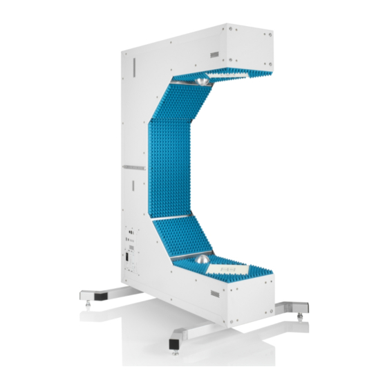
® Instrument tour R&S QAR50 System overview Figure 5-1: System overview Mounting holes Supporting feet Connector board Verification kit mounting rail Calibration sphere Antenna cluster 1 Antenna cluster 2 Absorbers 5.1.1 Connector board Number of connector boards: 1 Function: The connector board provides various interfaces for external applications. For more information about available connectors, see Chapter 5.2, "Connectors and labels",... -
Page 27: Antenna Cluster
® Instrument tour R&S QAR50 System overview 5.1.2 Antenna cluster Number of clusters: 2 Function: The antenna clusters are located in the side body of the R&S QAR50. The antenna clusters contain the transmit and receive antennas. These antennas transmit and receive the signals to and from the DUT and digitize the resulting incident wave quantities, which are in turn the source for the microwave imaging. -
Page 28: Supporting Feet
® Instrument tour R&S QAR50 Connectors and labels For more information about system calibration, contact your service representative or refer to the service manual. 5.1.6 Supporting feet Number of supporting feet: 2 Function: The supporting feet provide a means to support the R&S QAR50. Depending on how you install the R&S QAR50, the supporting feet are either located on the bottom of the main body of the R&S QAR50 or on the side body that contains cluster "2". -
Page 29: Ac Power Supply
® Instrument tour R&S QAR50 Connectors and labels Figure 5-2: Connector overview USB ports Power button USB ports (behind protective cover) 4 = Lock for protected USB port LAN interface DisplayPort AC power supply 8 = Sticker with device ID 5.2.1 AC power supply Connector type: IEC 60320-1 C14 Function: AC input for a connection to the AC mains supply. -
Page 30: Power Button
® Instrument tour R&S QAR50 Connectors and labels Figure 5-3: AC power supply 5.2.2 Power button Function: A short press turns the R&S QAR50 on and off when it is connected to an AC power source The power button contains an LED that indicates the state of the R&S QAR50. For more information about the power states, see Chapter 4.6, "Switching on or off",... - Page 31 ® Instrument tour R&S QAR50 Connectors and labels Figure 5-6: USB port 5.2.5 DisplayPort connector Connector type: DisplayPort Function: DisplayPort for connection of a touchscreen or monitor that you can use to control the R&S QAR50 and view the measurement results. Figure 5-7: DisplayPort connector 5.2.6 Device ID The unique device identifier is provided as a barcode sticker on the connector board on...
Need help?
Do you have a question about the R&S QAR50 and is the answer not in the manual?
Questions and answers