
Related Manuals for Rohde & Schwarz R&S QAR


Summary of Contents for Rohde & Schwarz R&S QAR
- Page 1 ® R&S Quality Automotive Radome Tester User Manual (;ÜÖ02) 1178720002 Version 09...
- Page 2 ® This document describes the following R&S QAR models and options: ● ® R&S QAR QAR Panel for reflectivity measurements (1336.6008.02) ● ® R&S QAR-Z10 Transmitter module (1336.5401.02) ● ® R&S QAR-Z20 Platform (1336.5418.02) ● ® R&S QAR-Z21 Platform for radar positioning measurements (1336.5524.02) ●...
-
Page 3: Table Of Contents
® Contents R&S Contents 1 Safety and Regulatory Information............7 Safety Instructions......................7 Korea Certification Class B..................9 2 Documentation Overview..............10 3 R&S QAR Tour..................11 Main Power Supply..................... 12 Power Button.......................14 Transmitter Module Control..................14 Monitor Connectors....................15 LAN Interface.......................15 USB Ports........................ - Page 4 ® Contents R&S 5.1.4 Configuration.........................44 5.1.5 Verification........................50 Single Cluster Radome Measurements..............54 5.2.1 Test Setup........................54 5.2.2 Graphical User Interface....................56 5.2.3 Measurements......................57 5.2.4 Configuration.........................60 5.2.5 Verification........................61 Bumper Measurements....................62 5.3.1 Test Setup........................63 5.3.2 Graphical User Interface....................63 5.3.3 Measurements......................
- Page 5 ® Contents R&S 7.2.2 Data Types........................106 7.2.3 Examples........................106 Device States......................109 Timing Diagram......................110 Error Handling......................110 8 Maintenance..................113 Cleaning Information....................113 Software Update......................114 Storage........................117 Transport........................117 Disposal........................118 9 Contacting Customer Support............119 Glossary....................120 Index....................122 User Manual 1178.7200.02 ─ 09...
- Page 6 ® Contents R&S User Manual 1178.7200.02 ─ 09...
-
Page 7: Safety And Regulatory Information
® Safety and Regulatory Information R&S Safety Instructions 1 Safety and Regulatory Information The product documentation helps you use the R&S QAR safely and efficiently. Follow the instructions provided here and in the safety instructions. Intended use The product is intended for the development, production and verification of electronic components and devices in industrial, administrative, and laboratory environments. - Page 8 ® Safety and Regulatory Information R&S Safety Instructions ing the installation, make sure that the installation site is only accessible to people working on the installation. Hold the R&S QAR into position until all screws are tight to prevent it from falling over. Because of its weight, at least two strong people are required to move or install the R&S QAR.
-
Page 9: Korea Certification Class B
® Safety and Regulatory Information R&S Korea Certification Class B ● If the voltage or frequency is higher than 230 V or 50 Hz, the leakage current of the R&S QAR can be above the limits. In that case, a protective ground connection must be established for each panel before connecting them to the power supply. -
Page 10: Documentation Overview
® Documentation Overview R&S 2 Documentation Overview This section provides an overview of the R&S QAR user documentation. User manual Contains a description of the R&S QAR system, including the features available in the R&S QAR application. A digital version of the user manual is available in the measurement application. A printed version of the user manual is part of the delivery. -
Page 11: S Qar Tour
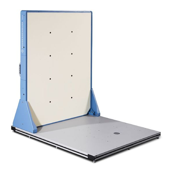
® R&S QAR Tour R&S 3 R&S QAR Tour The R&S QAR is a millimeter wave imaging system operating in the frequency band of automotive radar sensors. With its support of spatially resolved reflection and transmis- sion loss measurements, the R&S QAR provides an intuitive and powerful way to eval- uate how radomes and bumpers influence the radar performance. -
Page 12: Main Power Supply
® R&S QAR Tour R&S Main Power Supply ● USB Keyboard ● USB Mouse Connectors The R&S QAR has several connectors on its back side. Figure 3-1: Connectors 1 = Power button 2 = USB ports (4x) 3 = Display connector (DVI) 4 = LAN interface 5 = Power supply for a monitor (including 2 fuses) 6 = Transmitter module control... - Page 13 ® R&S QAR Tour R&S Main Power Supply The main power switch contains an RCD (residual-current device) that protects the internal power circuit of the R&S QAR. If the RCD detects electrical anomalies, it will switch off automatically the R&S QAR. For more information about supplying the panel with power, see Chapter 4.4, "Switch- ing the R&S QAR On and...
-
Page 14: Power Button
® R&S QAR Tour R&S Transmitter Module Control We recommend that you use a power cable that is rated for a 16 A (included in the delivery) and connect each panel to a separately protected power circuit (at least 10 A). If you cannot connect the panels to separate power circuits, make sure that the system is protected: ●... -
Page 15: Monitor Connectors
® R&S QAR Tour R&S LAN Interface Transmitter control The "External Transmitter Control" connector controls the transmitter module. RF out The "RF Out" connector (SMA) outputs the signal for the transmission measurement. Do not feed a DC or RF signal into the RF output, because it is specified as an output only. -
Page 16: Usb Ports
® R&S QAR Tour R&S USB Ports Figure 3-5: LAN interface 3.6 USB Ports The R&S QAR provides 4 USB ports on the back side. The two top ports are USB 3.0 type A. The two bottom ports are USB 2.0 type A. They offer multiple uses: ●... -
Page 17: Preparing For Use
® Preparing for Use R&S Installing the R&S QAR 4 Preparing for Use Before you can use the R&S QAR, install it and connect the devices as described in the next subchapters. ● Unpacking the R&S QAR..................17 ● Installing the R&S QAR...................17 ●... -
Page 18: Installing The R&S Qar On The Floor
® Preparing for Use R&S Installing the R&S QAR ● Anchor bolts size 12 mm, for example a Fischer FAZ II 12 (for floor installation only) ● Installing the R&S QAR on the Floor...............18 ● Installing the R&S QAR on the Platform (R&S QAR-Z20)........ - Page 19 ® Preparing for Use R&S Installing the R&S QAR A = Drill hole location for R&S QAR B = Drill hole location for DUT mounting table Whenever you lift, move or carry the R&S QAR, use the handles on its back side. 2.
-
Page 20: Installing The R&S Qar On The Platform (R&S Qar-Z20)
® Preparing for Use R&S Installing the R&S QAR Figure 4-3: Support installation (top view) 4. Lift the R&S QAR into a stable position and in a right angle to the floor. 5. Secure the R&S QAR by screwing the two supports to the floor. The drill holes in the floor define the position of the supports. - Page 21 ® Preparing for Use R&S Installing the R&S QAR ● A counterclockwise movement raises the corresponding platform area. 4. Tighten the feet with the check nuts using the open-end wrench. Figure 4-4: Platform alignment Mounting the R&S QAR When the platform is in place, you can mount the R&S QAR on the platform. Whenever you lift, move or carry the R&S QAR, use the handles on its back side.
-
Page 22: Installing The Radome Measurement Elements
® Preparing for Use R&S Installing the R&S QAR 2. Lift the R&S QAR onto the platform into a stable position and in a right angle to the floor. 3. Secure the R&S QAR by screwing the two supports to the platform. The mounting holes in the platform define the position of the supports. - Page 23 ® Preparing for Use R&S Installing the R&S QAR Note: Insert a washer between screw and mounting table as shown in Figure 4-7. Figure 4-7: DUT mounting table and transmitter module installation Installing the DUT mounting table on the floor Altenatively, you can install the DUT mounting table directly on the floor.
-
Page 24: Installing The Bumper Measurement Elements
® Preparing for Use R&S Installing the R&S QAR Figure 4-8: DUT mounting table from above For more information about cable connections, see Chapter 4.3, "Connecting the R&S QAR", on page 31. 4.2.4 Installing the Bumper Measurement Elements The basic setup for bumper measurements consists of the R&S QAR and a reference reflector, including a stand for the reference reflector. - Page 25 ® Preparing for Use R&S Installing the R&S QAR ● Allen wrench size 6. ● Torx wrench size TX25. ● Spirit level Installing the reference reflector stand 1. Put the stand on the platform at the specified location. 2. Screw the stand to the platform with the four socket head screws (size 5). Insert a washer between screw and stand.
- Page 26 ® Preparing for Use R&S Installing the R&S QAR Figure 4-11: Possible misalignments of the reflector stand 1 = Lateral misalignment (x-axis) 2 = Vertical tilt 3 = Horizontal tilt 4 = Vertical misalignment (y-axis) 5 = Horizontal misaligment (z-axis) 6.
- Page 27 ® Preparing for Use R&S Installing the R&S QAR 1. Remove the covers on the base of the stand (2x), for example with a slotted screw- driver. 2. Loosen the screws on the base of the stand with an Allen wrench, size 6 (8x). 3.
- Page 28 ® Preparing for Use R&S Installing the R&S QAR 4. Move the reflector to the front or back as necessary. 5. Repeat normalization measurement. a) If normalization does no longer indicate a misalignment, reassemble the stand. b) If normalization still indicates a misalignment, repeat the adjustment until the error no longer occurs.
- Page 29 ® Preparing for Use R&S Installing the R&S QAR 1. Loosen the screws on the side of the support bar with an Allen wrench, size 6 (2x). 2. Turn the reflector to the right or left as necessary. 3. Repeat normalization measurement. a) If normalization does no longer indicate a misalignment, reassemble the stand.
-
Page 30: Installing The R&S Qar On The Platform (R&S Qar-Z21)
® Preparing for Use R&S Installing the R&S QAR b) If normalization still indicates a misalignment, repeat the adjustment until the error no longer occurs. 4.2.5 Installing the R&S QAR on the Platform (R&S QAR-Z21) Required tools: ● Allen wrench size 5 (for screws ISO 10642 M8x20) ●... -
Page 31: Connecting The R&S Qar
® Preparing for Use R&S Connecting the R&S QAR Whenever you lift, move or carry the R&S QAR, use the handles on its back side. 1. Screw the two supports to the R&S QAR with four socket head screws (size 5) on each side of the R&S QAR (see Figure 4-13). -
Page 32: Switching The R&S Qar On And Off
® Preparing for Use R&S Switching the R&S QAR On and Off Required tools: ● Torque wrench (order no. 0041.1218.00). Monitor (DVI + power) Keyboard (USB) Mouse (USB) R&S QAR AC Power Transmitter module (Radome measurements) Figure 4-14: Connection overview in a system with optional transmitter module 1. -
Page 33: Operating System
® Preparing for Use R&S Operating System For more information, see Chapter 3.1, "Main Power Supply", on page 12. 2. Connect the power cable to the AC inlet. 3. Connect the power cable to the mains supply. 4. Turn on the main power switch (position "I"). The R&S QAR is supplied with power. -
Page 34: Virus Protection
® Preparing for Use R&S Operating System The drivers and software installed on the R&S QAR are adapted to the R&S QAR. Only install software updates released by Rohde & Schwarz. 4.5.1 Virus Protection Take appropriate steps to protect your instruments from infection. Use strong firewall settings and scan any removable storage device used with a Rohde &... - Page 35 ® Preparing for Use R&S Operating System Changing the passwords For security reasons, we recommend that you to change the passwords. User Manual 1178.7200.02 ─ 09...
-
Page 36: Operating The R&S Qar
® Operating the R&S QAR R&S 5 Operating the R&S QAR The application to operate the R&S QAR is installed on a PC that is integrated into the R&S QAR. It starts automatically when you turn on the R&S QAR. Warm-up time Let the R&S QAR warm up for at least 90 minutes before using it. -
Page 37: Radome Measurements
® Operating the R&S QAR R&S Radome Measurements For a detailed description of the features of the R&S License Manager, refer to its inte- grated help (available via the "?" icon) or the documentation available on Gloris. 5.1 Radome Measurements For radome measurements, the R&S QAR measures the characteristics of a DUT using its full 12 clusters. - Page 38 ® Operating the R&S QAR R&S Radome Measurements Figure 5-1: Basic test setup (distances in mm) Figure 5-1, the box indicates the area in which the R&S QAR takes the image of the DUT. Note that the DUT must be positioned slightly off-center to the center of the R&S QAR as indicated in Figure 5-1 (142.5 mm).
-
Page 39: Graphical User Interface
® Operating the R&S QAR R&S Radome Measurements Numbers without brackets = dimensions in mm Numbers in brackets = dimensions in inch 5.1.2 Graphical User Interface The graphical user interface (GUI) contains several elements. Figure 5-3: Software graphical user interface 1 = Menu bar 2 = Measurement description 3 = Result display (reflection) - Page 40 ® Operating the R&S QAR R&S Radome Measurements The transmission loss result display shows the results of the transmission measure- ment. Numeric results Several numeric results of the reflection and transmission measurements are dis- played. ● Mean reflection ● Standard deviation ●...
-
Page 41: Measurements
® Operating the R&S QAR R&S Radome Measurements Table 5-1: Keyboard shortcuts Ctrl-S Saves the currently displayed measurement results. "Managing measurement results" on page 48 for details. Ctrl-O Opens a dialog box to load measurement results. "Managing measurement results" on page 48 for details. - Page 42 ® Operating the R&S QAR R&S Radome Measurements remove those deviations from the actual measurement results, which in turn improves the accuracy of the measurement. Normalizing reflection measurements Normalizing the reflection measurement requires a clean, smooth and flat metallic plate for a high reflection, for example aluminum. The recommended size is between 100 mm x 100 mm and 200 mm x 200 mm.
- Page 43 ® Operating the R&S QAR R&S Radome Measurements 5.1.3.2 Reflection Measurement The reflection measurement determines the amount of energy that is being reflected by the DUT. This energy does not pass through the radome and contributes to perfor- mance degradation as a result. Reflected signals reduce the performance of the radar and can even interfere with the received signals, leading to effects as described in application note 1MA267.
-
Page 44: Configuration
® Operating the R&S QAR R&S Radome Measurements points to cover a selected frequency span between 72 GHz and 82 GHz. This allows for an exact evaluation of the DUT's transmission frequency response. The frequency response yields detailed information regarding the RF transmission loss of the DUT at the exact frequency band intended for radar operation. - Page 45 ® Operating the R&S QAR R&S Radome Measurements The R&S QAR reevaluates the mean reflection and the standard deviation. 4. Optional: Export the evaluation mask. a) Select "Options" > "Reflection Mask" b) Select "Save Bitmap" to save the shape and location of the mask as a bitmap (.bmp file).
- Page 46 ® Operating the R&S QAR R&S Radome Measurements You can design two layers in the grid ("Grid 1" and "Grid 2") and thus refine the evalua- tion areas. Using two grids can be useful to increase the defect localization resolution without sacrificing the averaging over a larger cell size.
- Page 47 ® Operating the R&S QAR R&S Radome Measurements a) Select the grid whose cells you want to exclude "Grid 1" or "Grid 2". Excluding cells is not possible while both grids are displayed in the preview. b) Write the cell numbers into the input field, separated by a ":", for example: "1:2:4:5".
- Page 48 ® Operating the R&S QAR R&S Radome Measurements Figure 5-6: Grid evaluation example 1 = Green cells indicate master cells 2 = Blue grid indicates cells of "Grid 1" (not shown: a yellow grid indicates cells of "Grid 2") 3 = Red cells indicate a violation of the threshold somewhere in the area the cell covers Managing measurement results You can export the measurement data, for example to store it on an external memory device or copy it to a different computer for further analysis with different software.
- Page 49 ® Operating the R&S QAR R&S Radome Measurements Image of the reflection and transmission loss measurement. ● Protocol.csv Contains the numerical measurement results. ● <yyyy-mm-dd-hh-mm-ss>_results.mat Contains the raw 2D imaging data. Only if you have selected the data package "Statistics + Pictures + Data". This data package is necessary if you want to restore the measurement results later ●...
-
Page 50: Verification
® Operating the R&S QAR R&S Radome Measurements The R&S QAR supports the barcode scanner Honeywell Xenon 1900 by Honeywell International Inc. 1. Select "Options" > "Recording". 2. Select "Use Barcode Scanner". 3. Select the (serial) port the barcode scanner is connected to from the dropdown menu. - Page 51 ® Operating the R&S QAR R&S Radome Measurements R&S QAR-Z40 R&S QAR-Z43 Figure 5-7: Test setup for verification of radome measurements 1 = Verification frame holding verification object Required equipment All required equipment is included in the delivery of the verification set. ●...
- Page 52 ® Operating the R&S QAR R&S Radome Measurements R&S QAR-Z40 R&S QAR-Z43 Figure 5-8: Verification object frame installation 1 = Position of the frame 2 = Frame screws (4 x) 1. Place the frame on the mounting table. The position of the frame is defined by the mounting holes in the DUT mounting table.
- Page 53 ® Operating the R&S QAR R&S Radome Measurements a) Put the metal plate labeled "E" into the frame. b) Select "Normalize Reflection" to initiate a measurement. c) Wait until the results are displayed. d) Remove the metal plate from the frame. The resulting image should show a homogeneous image (the colors should not deviate too much).
-
Page 54: Single Cluster Radome Measurements
® Operating the R&S QAR R&S Single Cluster Radome Measurements d) Do the same for the other two plastic plates labeled B and C. After each measurement, check the mean transmission loss against the limits a and a specified on the stickers attached to the verification plates. The sticker shows the attenuation characteristics of the plate and the deviation the result may have. - Page 55 ® Operating the R&S QAR R&S Single Cluster Radome Measurements Figure 5-9: Setup for single cluster measurements The DUT must be positioned directly opposite to the cluster that measures the DUT and therefore slightly off-center to the center of the R&S QAR. Figure 5-10, the box indicates the area in which the R&S QAR takes the image of the DUT.
-
Page 56: Graphical User Interface
® Operating the R&S QAR R&S Single Cluster Radome Measurements 5.2.2 Graphical User Interface The graphical user interface (GUI) contains several elements. Figure 5-11: Software graphical user interface for single cluster measurements 1 = Menu bar 2 = Measurement description 3 = Single cluster measurement selection 4 = Result display (reflection) 5 = Overview test setup... -
Page 57: Measurements
® Operating the R&S QAR R&S Single Cluster Radome Measurements Settings and control buttons Several settings and buttons allow you to control the measurement. ● "Measure" Initiates a measurement. For more information, see Chapter 5.2.3, "Measurements", on page 57. ● "Normalize Reflection"... - Page 58 ® Operating the R&S QAR R&S Single Cluster Radome Measurements on page 43 for details. For single cluster measurements, the R&S QAR uses the clus- ter indicated in Figure 5-12 and a fix bandwidth of 1 GHz, a typical bandwidth for auto- motive radar applications.
- Page 59 ® Operating the R&S QAR R&S Single Cluster Radome Measurements Figure 5-13: Image of a homogenous DUT 1 = Size of the image (in mm) 2 = Evaluation area 3 = Area that contains values for mean reflection 4 = Color map The measurement points (or areas of measurement points) that the R&S QAR uses to calculate the mean reflection with are also highlighted.
-
Page 60: Configuration
® Operating the R&S QAR R&S Single Cluster Radome Measurements For inhomogeneous DUTs, the distribution can be different, so there maybe several highlighted areas in the image, but the evaluation remains the same. max. reflection value range for mean reflection - 3 dB threshold Figure 5-15: Mean reflection on an inhomogeneous DUT Performing the measurement sequence... -
Page 61: Verification
® Operating the R&S QAR R&S Single Cluster Radome Measurements 5.2.5 Verification The R&S QAR provides a verification procedure to validate the quality of the measure- ments. Verification consists of a series of measurements with standardized DUTs which are located at a fix distance from the R&S QAR. If verification fails, validate the verification setup. -
Page 62: Bumper Measurements
® Operating the R&S QAR R&S Bumper Measurements 5.3 Bumper Measurements In real cases, the vehicle built-in radar sends a signal that crosses the bumper, is reflected and crosses the bumper again. Similarly, the R&S QAR antennas send sig- nals that cross the bumper, are reflected from the reference reflector pins and cross the bumper back. -
Page 63: Test Setup
® Operating the R&S QAR R&S Bumper Measurements 2. Normalize the measurement, as described in Chapter 5.3.3.1, "Normalization", on page 66. 3. Place the bumper to measure in the right position, as described in Chapter 5.3.1, "Test Setup", on page 63. 4. - Page 64 ® Operating the R&S QAR R&S Bumper Measurements 7 = Save button 8 = Status bar 9 = Numeric results (mean attenuation), incl. result indicator 10 = Measure button 10 = Result display Result display Shows the millimeter wave image of the data collected from the reference reflector pins during the scan.
-
Page 65: Measurements
® Operating the R&S QAR R&S Bumper Measurements ● "Options" Contains functionality to configure the measurement and result displays. For more information, see "Managing measurement results" on page 67. ● "Info" Contains various information about the application, including information about open source software licenses and the user manual. -
Page 66: Configuration
® Operating the R&S QAR R&S Bumper Measurements 5.3.3.1 Normalization Normalization is a measurement done in the free space, to obtain a reference value for the bumper measurements. You do not need any object to measure or additional ele- ment. Normalization enables you also to check the positioning and the status of the reference reflector. - Page 67 ® Operating the R&S QAR R&S Bumper Measurements Managing bumber types To get valid results in the bumper measurement, you have to select the bumper model you want to measure first. Upon delivery, the R&S QAR does not contain any bumper data. For each bumper type you want to measure, you have to add the corresponding bumper characteristics first, based on the CAD data of your bumpers.
-
Page 68: Verification
® Operating the R&S QAR R&S Bumper Measurements The contents depend on your selection. – If you have selected the data package "Statistics + Pictures + Data", the file contains the raw 2D imaging data. This data package is necessary if you want to restore the measurement results later on. - Page 69 ® Operating the R&S QAR R&S Bumper Measurements If verification fails, validate the verification setup. If verification fails several times in a row, despite a valid setup, contact Rohde & Schwarz customer support to calibrate the R&S QAR and check the hardware. Warm-up time Let the R&S QAR warm up for at least 90 minutes before using it.
- Page 70 ® Operating the R&S QAR R&S Bumper Measurements Figure 5-19: Placing the verification plate Performing verification The verification process consists of three consecutive measurements using the verifi- cation plates. The plates are labeled "A" to "C". Each plate has a sticker with an arrow indicating the correct orientation and the expected attenuation value with acceptable error margin.
-
Page 71: Radar Positioning Measurements
® Operating the R&S QAR R&S Radar Positioning Measurements 5.4 Radar Positioning Measurements The typical procedure when measuring a radar position is as follows: 1. Start the R&S QAR to start the system and the software. For more information about the functionality of the software, see Chapter 5.4.2, "Graphical User Interface",... -
Page 72: Graphical User Interface
® Operating the R&S QAR R&S Radar Positioning Measurements Figure 5-21: Test setup for radar positioning measurements (view from above) 5.4.2 Graphical User Interface The graphical user interface (GUI) contains several elements. Figure 5-22: Software graphical user interface 1 = Menu bar 2 = Car type 3 = Description 4 = Graphical results... - Page 73 ® Operating the R&S QAR R&S Radar Positioning Measurements Result display (graphic and numeric) Graphic and numeric measurement results. For more information, see Chapter 5.4.3, "Measurement", on page 74. Settings and control buttons Several settings and buttons allow you to control the measurement. ●...
-
Page 74: Measurement
® Operating the R&S QAR R&S Radar Positioning Measurements Table 5-4: Keyboard shortcuts Ctrl-S Saves the currently displayed measurement results. "Managing measurement results" on page 78 for details. Ctrl-O Opens a dialog box to load measurement results. "Managing measurement results" on page 78 for details. - Page 75 ® Operating the R&S QAR R&S Radar Positioning Measurements ● If you turn on "Save Screenhot", the image is a 2D image that shows the DUT from the front. ● If you turn off "Save Screenhot", the image is a 3D image. You can turn the image in any direction and view it from different angles.
-
Page 76: Configuration
® Operating the R&S QAR R&S Radar Positioning Measurements 5.4.4 Configuration The R&S QAR provides several tools to configure the measurement. Selecting the user interface The radar positioning measurement application provides two user interfaces, simple and advanced. ► Select "Options" > "Advanced Mode" to switch between user interfaces. ●... - Page 77 ® Operating the R&S QAR R&S Radar Positioning Measurements 3. Optional: If you change any settings that have an effect on the car type configura- tion (for example limits), select "File" > "Configuration" > "Export Configuration" to export the updated configuration. Defining alarm limits Alarm limits define by how much the position of the radar module may deviate from the ideal position.
- Page 78 ® Operating the R&S QAR R&S Radar Positioning Measurements Selecting the user interface language You can display the user interface in various languages. ► Select "Options" > "Languages". Changing the language requires a restart of the application. Managing measurement results You can export the measurement data, for example to store it on an external memory device or copy it to a different computer for further analysis with different software.
-
Page 79: Verification
® Operating the R&S QAR R&S Radar Positioning Measurements Remote controlling radar positioning measurements You can remote control radar positioning measurements via a Modbus protocol. 1. Select "Options" > "Modbus Communication". Several new input fields and control buttons appear in the user interface. 2. - Page 80 ® Operating the R&S QAR R&S Radar Positioning Measurements Figure 5-24: Verification setup (side view) ● The verification object has an offset of 14.5 cm to the right of the center of the R&S QAR. Figure 5-25: Verification setup (view from above) Verifying the system The verification is a series of three consecutive measurements with the verification objects.
- Page 81 ® Operating the R&S QAR R&S Radar Positioning Measurements 4. Start a measurement ("Measure"). 5. Repeat the procedure for all three verification objects. Verification passes if the measurement results for all three objects are within the limits (measurement result is "OK"). 6.
-
Page 82: Remote Control - Scpi
® Remote Control - SCPI R&S Remote Control Interface and Protocol 6 Remote Control - SCPI ● Remote Control Interface and Protocol..............82 ● Remote Commands....................84 6.1 Remote Control Interface and Protocol For the R&S QAR, the remote control interface is the LAN interface. The LAN interface consists of a connector, a network interface card and protocols. - Page 83 ® Remote Control - SCPI R&S Remote Control Interface and Protocol Identifying instruments in a network If several instruments are connected to the network, each instrument has its own IP address and associated resource string. The controller identifies these instruments by the resource string.
-
Page 84: Remote Commands
® Remote Control - SCPI R&S Remote Commands 6.2 Remote Commands ● Data Management....................84 ● General Configuration..................... 86 ● Measurement Control....................87 ● Radome Measurements..................87 ● Bumper Measurements...................96 ● System........................99 6.2.1 Data Management ....................... 84 MEASurement:LOAD ..................84 MEASurement:RESult:DIRectory ................... 84 MEASurement:RESult:SAVE:AUTO ...................85 MEASurement:RESult:SAVE:WHAT... -
Page 85: Measurement:save
® Remote Control - SCPI R&S Remote Commands OFF | 0 Results are not saved automatically. *RST: Example: //Turn on automatic saving of results MEAS:RES:SAVE:AUTO ON MEASurement:RESult:SAVE:WHAT <Data> This command selects which data to store when saving. Parameters: <Data> Stores statistics and pictures. Stores statistics, pictures and data. -
Page 86: General Configuration
® Remote Control - SCPI R&S Remote Commands 6.2.2 General Configuration ..................86 MEASurement:RESult:BCS:PORT ..................86 MEASurement:RESult:BCS:USE ..................86 MEASurement:RESult:SAVE:WBC MEASurement:RESult:BCS:PORT <Port> This command defines the port the barcode scanner is connected to. Prerequisites for this command ● Turn on barcode scanner (MEASurement:RESult:BCS:USE). Parameters: <Port>... -
Page 87: Measurement Control
® Remote Control - SCPI R&S Remote Commands 6.2.3 Measurement Control ....................... 87 MEASurement:STARt MEASurement:STARt This command initiates a measurement. We recommend to define a timeout of at least 10 seconds to allow for the measure- ment to finish. Example: //Initiate measurement MEAS:STAR Usage:... -
Page 88: Measurement:reflection:normalize:required
® Remote Control - SCPI R&S Remote Commands SYSTem:MODE:SC This command selects single cluster measurements. Example: //Select single cluster measurement SYST:MODE:SC Usage: Event 6.2.4.2 Measurements (12 Cluster) Remote commands described elsewhere: ● on page 84 MEASurement:LOAD ● on page 85 MEASurement:SAVE ●... -
Page 89: Measurement:reflection:statistics
® Remote Control - SCPI R&S Remote Commands We recommend to define a timeout of at least 10 seconds to allow for the measure- ment to finish. Example: //Normalize reflection measurement MEAS:REFL:NORM:STAR Usage: Event MEASurement:REFLection:STATistics<n>:MEAN? This command queries the mean reflection. Prerequisites for this command ●...:Mean -
Page 90: Measurement:reflection:statistics
® Remote Control - SCPI R&S Remote Commands MEASurement:REFLection:STATistics<n>:STD? This command queries the standard deviation of the reflection measurement. Prerequisites for this command ● Reflection measurement results must be available. Suffix: <n> 1: Result in dB 2: Result in % 3: Linear result You can query the unit of a result with MEASurement:...:Std -
Page 91: Measurement:transmission:band
® Remote Control - SCPI R&S Remote Commands Example: //Query start frequency of second frequency band MEAS:TRAN:BAND2:STAR:FREQ? Usage: Query only MEASurement:TRANsmission:BAND<n>:STATistics<m>:MEAN? This command queries the one-way mean attenuation of the transmission measure- ment. Suffix: <n> 1: First evaluated frequency band. 2: Second evaluated frequency band.:Statistics :Mean -
Page 92: Measurement:transmission:minfrequency
® Remote Control - SCPI R&S Remote Commands Return values: <StopFrequency> Default unit: GHz Example: //Query stop frequency of second frequency band MEAS:TRAN:BAND2:STOP:FREQ? Usage: Query only MEASurement:TRANsmission:MINFrequency? This command queries the frequency at which the minimum transmission loss has been measured. Return values: <Frequency>... -
Page 93: Measurement:transmission:vmod
® Remote Control - SCPI R&S Remote Commands We recommend to define a timeout of at least 10 seconds to allow for the measure- ment to finish. Example: //Normalize transmission measurement MEAS:TRAN:NORM:STAR Usage: Event MEASurement:TRANsmission:VMOD <State> This command turns the verification mode for a transmission loss measurement on and off. - Page 94 ® Remote Control - SCPI R&S Remote Commands Example: //Query mean reflection MEAS:STAR MEAS:REFL:SCST2:MEAN? Usage: Query only MEASurement:REFLection:SCSTatistics<n>:STD? This command queries the standard deviation of the reflection measurement. Prerequisites for this command ● Select single cluster measurement. ● Reflection measurement results must be available. Suffix: <n>...
- Page 95 ® Remote Control - SCPI R&S Remote Commands 6.2.4.4 Configuration Remote commands described elsewhere: ● on page 86 MEASurement:RESult:BCS:PORT ● on page 86 MEASurement:RESult:BCS:USE ● on page 84 MEASurement:RESult:DIRectory ● on page 84 MEASurement:RESult:SAVE:AUTO ● on page 86 MEASurement:RESult:SAVE:WBC ● on page 85 MEASurement:RESult:SAVE:WHAT ................
-
Page 96: Bumper Measurements
® Remote Control - SCPI R&S Remote Commands Example: //Import mask image MEAS:REFL:MASK:LOAD 'c:\masks\mymask.bmp' Usage: Setting only MEASurement:REFLection:MASK:SAVE <FileName> This command exports the shape of an evaluation mask and stores them in the .bmp file format. Setting parameters: <FileName> String that contains the file name and its location. Note that the file name must have the .bmp file extension. - Page 97 ® Remote Control - SCPI R&S Remote Commands Usage: Query only MEASurement:ATTenuation:STD? This command queries the standard deviation of the attenuation measurement. Prerequisites for this command: ● Attenuation measurement results must be available. Return values: <Deviation> Default unit: dB Example: //Query standard deviation of the attenuation measurement MEAS:STAR MEAS:ATT:STD?
- Page 98 ® Remote Control - SCPI R&S Remote Commands Measurement is not normalized. In that case, you should nor- malize the measurement before starting it. Example: //Query normalization state MEAS:NORM:REQ? Usage: Query only MEASurement:NORMalize:STARt This command initiates the normalization of an attenuation measurement. We recommend to define a timeout of at least 10 seconds to allow for the measure- ment to finish.
-
Page 99: System
® Remote Control - SCPI R&S Remote Commands Example: //Query the threshold value for the bumper type RR_L :MEAS:THR? 'RR_L' //Set a new threshold value for the bumper type RR_L :MEAS:THR 'RR_L', 1.0 6.2.5.2 Configuration Remote commands described elsewhere: ● on page 86 MEASurement:RESult:BCS:PORT ●... -
Page 100: System:error:message
® Remote Control - SCPI R&S Remote Commands Code Message Description Error occurred during initialization Contact service QAR hardware not initialized Contact service Invalid measurement type '<type>' Correct measurement type Invalid configuration '<config>' Correct measurement configuration Results are invalid Dismiss measurement results and repeat the measurement. -
Page 101: System:shutdown
® Remote Control - SCPI R&S Remote Commands Usage: Query only SYSTem:SHUTdown This command switches off the R&S QAR. Example: //Switch off system SYST:SHUT Usage: Event SYSTem:STATus:CODE? This command queries the system status. Return values: <StatusCode> Example: //Query system status SYST:STAT:CODE? Usage: Query only... -
Page 102: Remote Control - Opc
® Remote Control - OPC R&S OPC Variables 7 Remote Control - OPC OLE for process control (OPC) is an interface to communicate with the R&S QAR through a programmable logic controller (PLC). Rohde & Schwarz provides a client application, R&S QAROPCClient, that connects to an OPC server that hosts the variables used for communication with the PLC. - Page 103 ® Remote Control - OPC R&S OPC Variables User Manual 1178.7200.02 ─ 09...
- Page 104 ® Remote Control - OPC R&S OPC Variables User Manual 1178.7200.02 ─ 09...
- Page 105 ® Remote Control - OPC R&S OPC Variables User Manual 1178.7200.02 ─ 09...
-
Page 106: Data Types
® Remote Control - OPC R&S OPC Variables 7.2.2 Data Types The following table displays the number of bits required for each data type. Table 7-3: Variables data types Data type Number of bits Bool Float Double Integer All variables with data type "String" are represented by a byte array containing the string data (.DATA) and the number of characters in the string (.LEN). - Page 107 ® R&S Remote Control - OPC OPC Variables Diagnostics", "measure": "CompactLogix.CompactLogix_PLC.Global.QAR.FromPLC.Trigger.Measure" "path_diagnostics": "CompactLogix.CompactLogix_PLC.Global.QAR.FromPLC. Path_Diagnostics", "path_results": "CompactLogix.CompactLogix_PLC.Global.QAR.FromPLC.Path_Results", "type_measurement": "CompactLogix.CompactLogix_PLC.Global.QAR.FromPLC. Type_Measurement", "results_received": "CompactLogix.CompactLogix_PLC.Global.QAR.FromPLC. Results_Received", "heartbeat": "CompactLogix.CompactLogix_PLC.Global.QAR.FromPLC.Heartbeat" Variables for radome measurements "radome": { "radome_measurement": { "timestamp": "CompactLogix.CompactLogix_PLC.Global.QAR.ToPLC.RadomeMeasurement. Timestamp", "error_flag": "CompactLogix.CompactLogix_PLC.Global.QAR.ToPLC.RadomeMeasurement. Error_Flag", "reflection": { "window": { "width": "CompactLogix.CompactLogix_PLC.Global.QAR.FromPLC.RadomeMeasurement.
- Page 108 ® R&S Remote Control - OPC OPC Variables "min_loss": "CompactLogix.CompactLogix_PLC.Global.QAR.ToPLC.RadomeMeasurement. Transmission.Min_Loss" "state": { "initializing": "CompactLogix.CompactLogix_PLC.Global.QAR.ToPLC.State.Initiliazing", "malfunction": "CompactLogix.CompactLogix_PLC.Global.QAR.ToPLC.State.Malfunction", "processing": "CompactLogix.CompactLogix_PLC.Global.QAR.ToPLC.State.Processing", "ready_to_measure": "CompactLogix.CompactLogix_PLC.Global.QAR.ToPLC.State. Ready_ToMeasure", "results_ready": "CompactLogix.CompactLogix_PLC.Global.QAR.ToPLC.State.Results_Ready" "configuration_stem": "CompactLogix.CompactLogix_PLC.Global.QAR.ToPLC. Configuration_x.Configuration_", "num_configuration": 50, "process_time_sec": "CompactLogix.CompactLogix_PLC.Global.QAR.ToPLC.Process_Time_Sec", "error_flag": "CompactLogix.CompactLogix_PLC.Global.QAR.ToPLC.Error_Flag", "error_code": "CompactLogix.CompactLogix_PLC.Global.QAR.ToPLC.Error_Code", "heartbeat": "CompactLogix.CompactLogix_PLC.Global.QAR.ToPLC.Heartbeat" Variables for bumper measurements "bumper": { "bumper_measurement": { "attenuation_mean": "CompactLogix.CompactLogix_PLC.Global.QAR.ToPLC.
-
Page 109: Device States
® Remote Control - OPC R&S Device States "error_code": "CompactLogix.CompactLogix_PLC.Global.QAR.ToPLC.Error_Code", "heartbeat": "CompactLogix.CompactLogix_PLC.Global.QAR.ToPLC.Heartbeat" 7.3 Device States While operating, the R&S QAR runs through different states as shown in Figure 7-2. 1. The device starts in State.Initializing. 2. The initialization runs: ● If initialization succeeds, the next state is State.Ready_ToMeasure. -
Page 110: Timing Diagram
® Remote Control - OPC R&S Error Handling 7.4 Timing Diagram The timing of communication for measurements and diagnostics between the PLC and the R&S QAR is identical. After the R&S QAR sets State.Results_Ready, PLC can read the results. R&S QAR discards measurement results after the PLC sets Results_Received. - Page 111 ® Remote Control - OPC R&S Error Handling User Manual 1178.7200.02 ─ 09...
- Page 112 ® Remote Control - OPC R&S Error Handling User Manual 1178.7200.02 ─ 09...
-
Page 113: Maintenance
® Maintenance R&S Cleaning Information 8 Maintenance Daily maintenance or inspection is not required for the R&S QAR. We recommend to do a verification at least every six months. ● Cleaning Information..................... 113 ● Software Update....................114 ● Storage........................117 ● Transport....................... 117 ●... -
Page 114: Software Update
® Maintenance R&S Software Update Do not use chemical cleaning agents or solvents like alcohol or cellulose lacquer thinners. Cleaning the transmitter module (R&S QAR-Z10) 1. Clean the horn antenna, cables and cable connectors carefully with a dry and soft, lint-free dust cloth. - Page 115 ® Maintenance R&S Software Update 4. Close all software that is still running and log out of the system. 5. Log into the system as an administrator. 6. NOTICE! Backup your data. Before you upgrade the operating system, back up the current image and your personal data to an external memory device, for example an external hard disk.
- Page 116 ® Maintenance R&S Software Update The upgrade consists of the following processes: ● Booting WinPE to create a recovery partition. When this is done, the R&S QAR restarts. ● Copying the calibration data to the USB stick. ● Installing the Windows 10 image. ●...
-
Page 117: Storage
® Maintenance R&S Transport 4. Attach the license sticker to R&S QAR frame, next to the USB ports. Your R&S QAR is now running Windows 10 and ready to use. We recommend changing the default user account passwords for improved security. If there are any issues with software availability, stability or missing licenses, feel free to reach out to your local sales force. -
Page 118: Disposal
® Maintenance R&S Disposal Transport altitude Unless otherwise specified in the data sheet, the maximum transport altitude without pressure compensation is 4500 m above sea level. 8.5 Disposal Rohde & Schwarz is committed to making careful, ecologically sound use of natural resources and minimizing the environmental footprint of our products. -
Page 119: Contacting Customer Support
® Contacting Customer Support R&S 9 Contacting Customer Support Technical support – where and when you need it For quick, expert help with any Rohde & Schwarz product, contact our customer sup- port center. A team of highly qualified engineers provides support and works with you to find a solution to your query on any aspect of the operation, programming or applica- tions of Rohde &... -
Page 120: Glossary
® Glossary R&S Glossary Calibration: Determines reproducible system characteristics and reduces the corre- sponding measurement deviations, thus increasing measurement accuracy signifi- cantly. The calibration set is available as accessory (R&S QAR-Z30). DUT: Device under test. For the R&S QAR, the DUT is usually a radome or a bumper. Mean reflection: Mean value of the reflection measured in the analyzed area of the DUT. - Page 121 ® Glossary R&S Reflection: The part of the signal that is reflected by the DUT. Result display: Diagram that shows the measurement results. Standard deviation: Result that indicates the dispersion of the measured reflection values. The standard deviation indicates the homogeneity of the DUT. Transmission loss: Measure of attenuation of the DUT over a certain frequency range.
-
Page 122: Index
® Index R&S Index Operating system .............. 33 service packs .............. 34 Barcode scanner ........... 49, 68, 79 Operation ................36 Bumper measurements ............. 62 Bumper measurements ..........62 Attenuation measurement ........... 66 Radar positioning measurement ......... 71 Normalization .............. 66 Radome measurements ........ - Page 123 ® Index R&S User interface Bumper measurements ..........63 Radar positioning measurements ....... 72 Radome measurements ..........39 Single cluster radome measurements ......56 User interface language ............ 78 User interface mode ............76 Verification .................79 Bumper measurements ..........68 Radome measurements ........
Need help?
Do you have a question about the R&S QAR and is the answer not in the manual?
Questions and answers