Sign In
Upload
Download
Table of Contents
Contents
Add to my manuals
Delete from my manuals
Share
URL of this page:
HTML Link:
Bookmark this page
Add
Manual will be automatically added to "My Manuals"
Print this page
×
Bookmark added
×
Added to my manuals
Manuals
Brands
Rohde & Schwarz Manuals
Test Equipment
R&S RTO Series
Getting started
Rohde & Schwarz R&S RTO Series Getting Started
Digital oscilloscope
Hide thumbs
1
2
3
4
5
6
7
8
9
10
11
12
13
14
15
16
17
18
19
20
21
22
23
24
25
26
27
28
29
30
31
32
33
Table Of Contents
34
35
36
37
38
39
40
41
42
43
44
45
46
47
48
49
50
51
52
53
54
55
56
57
58
59
60
61
62
63
64
65
66
67
68
69
70
71
72
73
74
75
76
77
78
79
80
81
82
83
84
85
86
87
88
89
90
91
92
93
94
95
96
97
98
99
100
101
102
103
104
105
106
107
108
109
110
111
112
113
114
115
116
117
118
119
120
121
122
123
124
125
126
127
128
129
130
131
132
133
page
of
133
Go
/
133
Contents
Table of Contents
Bookmarks
Table of Contents
Table of Contents
1 Preface
Key Features
Documentation Overview
Conventions for Procedure Descriptions
Conventions Used in the Documentation
Typographical Conventions
Notes on Screenshots
2 Preparing for Use
Positioning the Instrument
Unpacking and Checking the Instrument
Standalone Operation
Rackmounting
Starting the Instrument
Powering on
Powering off
Starting up and Shutting down
Connecting USB Devices
EMI Suppression
Connecting External Devices
Connecting an External Monitor
3 Instrument Tour
Front Panel
Touchscreen Display
SETUP Controls
HORIZONTAL Controls
TRIGGER Controls
VERTICAL Controls
ANALYSIS Keys
NAVIGATION Controls
Input Connectors
POWER Key
Other Font Panel Connectors
Rear Panel
Using the Standard Zoom
Using the Fingertip Zoom
Displaying the Waveform History
Showing Basic Measurement Results
Performing a Cursor Measurement
Performing an Amplitude Measurement
Performing and Configuring the Quick Measurement
Displaying a Histogram
Performing an FFT Analysis
Performing Mathematical Calculations
Performing a Search
Performing a Mask Test
Printing and Saving Screenshots
Saving Data
Using the Toolbar
Toolbar Functions
Toolbar Configuration
Working with Waveforms
Displaying Results
Using the Signal Bar
Accessing the Functionality
Entering Data
Messages
Getting Information and Help
4 Trying out the Instrument
Displaying a Basic Signal
Acquiring Data
Organizing the Display
Changing the Waveform Scaling and Position
Zooming into the Display
Displaying Tutorials
Displaying Help
Using the Help Window
5 Operating the Instrument
Means of Manual Interaction
Information on the Display
Toolbar
6 Setting up the Instrument
Performing a Self-Alignment
Aligning the Touchscreen
Setting the Display Language
Adjusting Passive Probes
Index
Advertisement
Quick Links
1
Key Features
2
Trigger Controls
3
Acquiring Data
4
Index
Download this manual
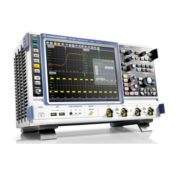
®
R&S
RTO
Digital Oscilloscope
Getting Started
(=@8Q2)
1316.0833.02 ─ 10
Table of
Contents
Previous
Page
Next
Page
1
2
3
4
5
Advertisement
Table of Contents
Need help?
Do you have a question about the R&S RTO Series and is the answer not in the manual?
Ask a question
Questions and answers
Related Manuals for Rohde & Schwarz R&S RTO Series
Test Equipment Rohde & Schwarz R&S RTO2000 Series Getting Started
(106 pages)
Test Equipment Rohde & Schwarz R&S ZV-Z51 Technical Information
Calibration units (4 pages)
Test Equipment Rohde & Schwarz R&S QAR User Manual
Quality automotive radome tester (123 pages)
Test Equipment Rohde & Schwarz R&S RTM3000 User Manual
(854 pages)
Test Equipment Rohde & Schwarz R&S RTM3000 Getting Started
(26 pages)
Test Equipment Rohde & Schwarz R&S RTB2000 User Manual
(609 pages)
Test Equipment Rohde & Schwarz R&S QAR50 Getting Started
Automotive radome tester (31 pages)
Test Equipment Rohde & Schwarz R&S CMW500 User Manual
Wideband radio communication tester (351 pages)
Test Equipment Rohde & Schwarz R&S RT-ZVC User Manual
Multichannel power probe (40 pages)
Test Equipment Rohde & Schwarz R&S TSME6 Getting Started
Ultracompact drive test scanner (40 pages)
Test Equipment Rohde & Schwarz R&S CBT Service Manual
Bluetooth tester (64 pages)
Test Equipment Rohde & Schwarz R&S CBT Operating Manual
Bluetooth tester (758 pages)
Test Equipment Rohde & Schwarz R&S CMW270 User Manual
Wireless connectivity tester (339 pages)
Test Equipment Rohde & Schwarz R&S RT-ZISO User Manual
Optical isolated probing system (51 pages)
Test Equipment Rohde & Schwarz R&S SFE Getting Started
Broadcast tester (76 pages)
Test Equipment Rohde & Schwarz R&S TS-PDFT User Manual
Digital function test module (51 pages)
This manual is also suitable for:
R&s rto1002
R&s rto1004
R&s rto1012
R&s rto1014
R&s rto1022
R&s rto1024
...
Show all
R&s rto1044
1316.1000k24
1316.1000k02
1316.1000k04
1316.1000k12
1316.1000k14
1316.1000k22
1316.1000k44
Table of Contents
Save PDF
Print
Rename the bookmark
Delete bookmark?
Delete from my manuals?
Login
Sign In
OR
Sign in with Facebook
Sign in with Google
Upload manual
Upload from disk
Upload from URL


Need help?
Do you have a question about the R&S RTO Series and is the answer not in the manual?
Questions and answers