Table of Contents

Related Manuals for 3M Dynatel 7550 Series


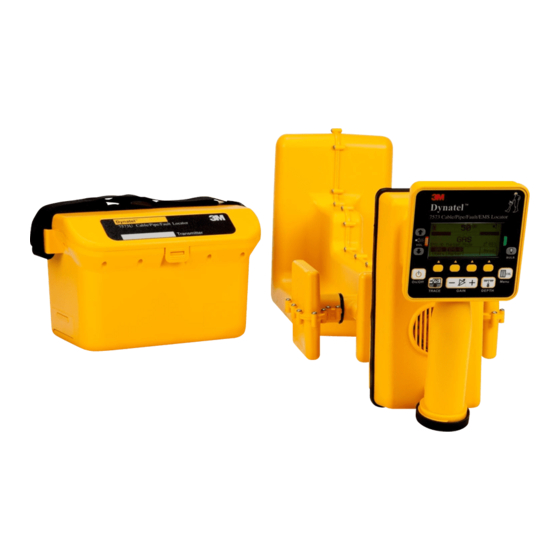
Summary of Contents for 3M Dynatel 7550 Series
- Page 1 Dynatel ™ ™ Cable/Pipe/Fault/EMS Locator 7550/7573 Series Operator’s Manual 7550-iD Pipe/Cable/EMS Locator 7573-iD Pipe/Cable/EMS Locator 7550E-iD Pipe/Cable/EMS Locator 7573E-iD Pipe/Cable/EMS Locator August 2015 78-9000-5020-0 Rev C...
-
Page 2: Table Of Contents
3.0 Quick Start ........................7 A. Locator Battery .................9 B. Charging the Receiver Battery.................9 C. Using Alkaline batteries...................9 D. Transmitter Battery Installation................10 E. 2200RB Battery Information.................10 F. 3M Dynatel Locator 7550 Transmitter Keypad and Connector Definitions..11 ™ ™ G. 3M Dynatel Locator 7573 Transmitter Keypad and Connector Definitions..11... - Page 3 A. Communicating with the GPS Unit...............57 B. Capturing the GPS Coordinates (Capture Mode / Mode 1)........57 C. Sending 3M iD Marker Data to GPS (Capture-Transmit Mode / Mode 2)...58 D. Path Mapping with GPS..................58 19.0 Help Mode .........................59 20.0 3M...
- Page 4 EMS Locators 7573 Series are designed with all of the functionality of previous Dynatel locator models plus the ability to locate 3M EMS Caution Tape 7600 Series. All Dynatel 7550 and 7573 locators have the capability to read and write user information to 3M ™...
-
Page 5: Safety Information
3M, the protections provided by the equipment may be impaired. WARNING If this equipment is used in a manner not specified by 3M, the protections provided by the equipment may be impaired. Explanation of Signal Word Consequences ! Warning: Indicates hazardous situation which if not avoided, could result in death or serious injury. - Page 6 • Do not pierce, modify or damage the battery, circuitry or packaging; • Do not allow the battery to get wet; • Only use the supplied charger or purchase a new charger from 3M; • Do not operate batteries outside of -20° to 50° C (-4 ° to 122 °F).
- Page 7 ! CAUTION To reduce the risks associated with environmental contamination and possible injury: The 12W transmitter utilizes the 3M™ Rechargeable 12V Battery 2200RB for the Maximim Output power level. This is a maintenance-free sealed lead (Pb)-acid battery. • Replace the battery if the acid solution leaks.
-
Page 8: About This Manual
™ ™ locator is designed for pipe/cable/EMS locating. The 7573 locator is designed for cable/ pipe/EMS and fault locating. The iD option (read/write capability to 3M iD Markers) ™ is standard for both models. The 7550/7573 Series transmitters are available in 3 watt, 5 watt and 12 watt units. -
Page 9: Quick Start
3. Quick Start A. Locator Battery Twist cap to open battery compartment. Slide battery into handle ensuring the text is facing left or right of the handle. B. Charging the Receiver Battery Pull back on the rubber plug cover Plug the AC charger into a power outlet. Plug the charging cord into the yellow power port [page 13 - item 11]. -
Page 10: Transmitter Battery Installation
= replace) E. 3M™ Rechargeable 12V Battery 2200RB Information The maintenance-free sealed lead (Pb)-acid 3M Rechargeable 12V Battery 2200RB ™ can be used as an auxiliary battery in 3M Dynatel Locator 7500 Series 12 Watt ™ ™ Transmitters. It plugs into the External Jack [T-7] and provides power for the transmitter. -
Page 11: Dynatel ™ Locator 7550 Transmitter Keypad And Connector Definitions
[T-6] Output Jack: Port for direct connect cables or Dyna-coupler cable. [T-7] External Jack: Port to connect cigarette lighter adapter cable, or rechargeable battery (2200RB). Input voltage level: 9-18 VDC. G. 3M Dynatel Locator 7573 Transmitter Keypad and Connector Definitions ™... -
Page 12: Maximum Transmitter Output
Active frequencies: 7573 577 Hz, 1 kHz, 8 kHz, 33 kHz, 82 kHz, 200 kHz 7573E (International) 577 Hz, 1 kHz, 8 kHz, 33 kHz, 82 kHz, 133 kHz ALL indicates that the following active frequencies are transmitting simultaneously: 7573 577 Hz, 8 kHz, 33 kHz, 200 kHz 7573E (International) 577 Hz, 8 kHz, 33 kHz, 133 kHz... -
Page 13: Cleaning Receiver And Transmitter Units
J. Service and Accessories Information regarding service, accessories, or replacement parts can be obtained by contacting 3M at 1-800-200-0265. K. Receiver External Cable Ports Definitions [9] Serial Port: RS232 port to connect the receiver to a PC via serial cable or USB- to-Serial Adapter cable. -
Page 14: Receiver Locate Screen Definitions
[18] Speaker Volume Icon: Indicates the relative volume level of the receiver. When the third ring is dotted and ‘xpnd' appears below the speaker volume icon, the receiver is in “Expander” mode. This mode is used to pinpoint the target cable or pipe. M. 3M Dynatel Receiver 7500 Keypad Definitions ™... -
Page 15: Menu Screens
Write History – 100 memory locations for written 3M iD Markers. ™ c. User Templates – Create and edit iD templates for 3M iD Markers (max=32). ™ d. Trace Templates – Create and edit templates used to identify path (max=5). - Page 16 COM Setup: Displays second level COM Port setting display to configure RS232 port communication with different devices – a. PC – Locator will communicate to a computer. b. NMEA – Port is configured to accept coordinates from GPS device according to NMEA (National Marine Electronics Association).
- Page 17 i. Depth Units – Choose unit of measure; in, ft-in, or cm. j. Marker Type – enable and disable marker utility types. k. Tone/Freq - External Port or Tone Frequencies – enable and disable frequencies that are detectable through the external port of the receiver.
-
Page 18: Configuring The Receiver
Menu/OK [6:Toggle to MAIN MENU] + >>More [SK:4] + [SK:5] + [SKToggle:a] The soft key command will toggle between available languages. Alternate languages can be uploaded to the receiver using the 3M™ Dynatel™ PC Tools software. (Available for download at www.3M.com/dynatel.) 78-9000-5020-0 Rev C... -
Page 19: Enabling/Disabling Locating Frequencies
D. Enabling/Disabling Locating Frequencies Menu/OK [6:Toggle to MAIN MENU] + >>More [SK:4] + [SK:5] + >>More [SK:d] + Locate Freq [SK:f] The user can select the frequencies that the receiver will detect. All the available frequencies are listed in four groups (Left to Right: Active, Power, Passive, and Auxiliary). -
Page 20: Selecting External Jack Frequencies (Tone Frequencies)
F. Selecting External Jack Frequencies (Tone Frequencies) Menu/OK [6:Toggle to MAIN MENU] + >>More [SK:4] + [SK:5] + >>More [SK:d] + >>More [SK:h] + Tone/Freq [SK:k] A coupler can be plugged into the External Jack [15] of the receiver and used to identify 50 Hz or 60 Hz cables. -
Page 21: Filtering Power Frequency Interference (User Defined Frequencies Only)
H. Filtering Power Frequency Interference (User Defined Frequencies Only) Menu/OK [6:Toggle to MAIN MENU] + >>More [SK:4] + [SK:5] + >>More [SK:d] + Locate Freq [SK:f] In order to filter out unwanted power influences while locating with user-defined frequencies, verify the correct frequency is selected for your location (default 60 Hz). -
Page 22: Locating Buried Cables And Pipes
6. Locating Buried Cables And Pipes A. Transmitter Connections Perform a battery test. Use one of the following three methods to produce a trace signal on the target pipe or cable. 1. Direct Connect Method WARNING This WARNING applies to the use of the Direct Connect Cables and the Transmitter. To avoid potential shock, or electrically damaging the Transmitter, when setting up the Transmitter to locate using the Direct Connect method, follow these basic steps;... - Page 23 − If the continuity of the circuit is very good (the reading on the display is less than 3K Ω and a solid tone from the transmitter is heard) all frequencies can be used to locate. Always use the lowest frequency available. Lower frequencies are less likely to ‘bleed over’...
- Page 24 2. 3M™ Dyna-Coupler Method WARNING This WARNING applies to the following 3M Dyna-Couplers; • 3" (75 mm) - Part number 3001 • 4.5" (114 mm) - Part number 4001 • 6" (150 mm) - Part number 1196 • All accessory kits containing any of the listed Dyna-Couplers - Part numbers 3019, 4519,...
- Page 25 3. Induction Method If you cannot make a direct connection, or use the 3M™ Dyna-Coupler clamp to apply a locating signal on the target, use the induction method. When nothing is plugged into the Output Jack [T-6] of the transmitter the unit will be placed into induction mode when it is turned on.
- Page 26 Active Induction allows for detecting buried cables and metal pipes in the absence of passive signals and at deep depths and short sections. 3M Dynatel transmitters provide a choice of induction frequencies and output power levels. Higher induction output power levels are needed for detecting deeper depths and longer ranges.
- Page 27 Walk in a grid pattern over the sweep area holding the receiver as shown in the following illustration. Stop when there is a response increase, locate the position of the maximum signal, follow the conductor path all the way out of the sweep area while putting location marks on the ground.
- Page 28 E. Two-person Active Induction Mode Sweeps In two-person active induction mode sweeps, one person holds the transmitter and the other holds the receiver while walking together in a sweep pattern detecting long conductors in the ground when crossed by transmitter and receiver positions and orientation, as shown below: Transmitter Set-up •...
-
Page 29: Receiver Locating Trace Modes
7. Receiver Locating Trace Modes A. Trace View (T-View) TRACE [3] Trace View mode, or T-View, provides an intuitive mapping display showing the utility path utilizing dynamic directional arrows and a path indication line. This combination provides an excellent visual representation of the utility path and directional assistance to assist in pinpointing the target. -
Page 30: Special Peak (Spl Pk)
Display 3. As the receiver antenna crosses the target, the receiver volume increases to a maximum, the signal strength will be at its maximum and the directional arrow will become a straight line that is closely lined up with the target line on the display. -
Page 31: Inductive Peak (Ind Pk)
Menu/OK [6] + Cable/Pipe [SK] + Mode [SK] + Ind Pk [SK Toggle] If you cannot make a direct connection, or use the 3M™ Dyna-Coupler clamp to apply a locating signal on the target, use the induction method. This method uses the internal coil of the transmitter to generate a magnetic field. -
Page 32: Directional Null (Dirnull)
E. Directional Null (DirNull) TRACE [3] + Mode [SK] + DirNull [SK Toggle] or Menu/OK [6] + Cable/Pipe [SK] + Mode [SK] + DirNull [SK Toggle] In Directional Null mode, as the operator approaches the cable or pipe, the numerical Signal Strength will increase then fall sharply as the receiver crosses the target cable or pipe. -
Page 33: Expanded Mode
F. Expanded Mode VOL [1] (press up arrow) When the third ring of the speaker icon is dotted or broken and ‘xpnd’ appears below the speaker icon as shown, the receiver is in “Expanded” mode. This mode is used for pinpointing a target cable or pipe. -
Page 34: Depth And Current Estimation
8. Depth and Current Estimate Verifying the target path, depth and current can be helpful tools. • Pinpoint the cable or pipe being located. • Lower the tip of the receiver to the ground and press DEPTH [5]. − The depth to the target cable or pipe is displayed in the units specified in the receiver set up menu. -
Page 35: Locating Frequencies
9. Locating Frequencies A. Active Frequencies Active frequencies are trace signals supplied by a 3M Dynatel Transmitter 7500 Series ™ ™ (577 Hz, 1 kHz, 8 kHz, 33 kHz, 82 kHz or 133 kHz /200 kHz). • Select the same frequency that the transmitter is generating. -
Page 36: Passive Frequencies
All International receivers default to 50 Hz. To set the receiver to detect 50 Hz signals refer to Enabling/Disabling Frequencies section of this manual. C. Passive Frequencies The receiver (without a 3M Dynatel Transmitter 7500 Series) can be used to detect ™... -
Page 37: Locating In Directional Peak Mode
10. Locating in Directional Peak Mode The following are instructions for locating a buried pipe or cable using the direct connect method and the Directional Peak (Dir Pk) mode. Other methods of connection and tracing modes/features are explained in previous sections. Step 1. - Page 38 Step 12. Set the Frequency and Mode of the receiver. a. Press Freq [SK]. b. Select the same frequency on the receiver that was selected on the transmitter by pressing Active [SK Toggle]. c. Press Menu/OK [6] to save the setting and return to Locate mode.
-
Page 39: Locating Active Duct Probes (Sondes)
Step 18. Measure the Depth and Current occasionally to verify target path. Note: In order to measure the Depth and Relative Current accurately, the operator must pinpoint the target pipe or cable, and the receiver handle should be in-line with the target path. -
Page 40: Determining Active Duct Probe Depth
A. Determining Active Duct Probe Depth Step 1. Place the tip of the receiver on the ground directly above the located ADP position. Step 2. Maintain the handle orientation perpendicular to the target path. Step 3. Press DEPTH [5]. Step 4. Press Sonde Depth [5] to read ADP Depth −... -
Page 41: Locating Buried Sheath Faults And Earth Return Faults (3M ™ Dynatel ™ Locator Models 7573 Only)
Output Level Flag B. Pinpointing the Buried Fault Step 1. Connect the 3M Earth Contact Frame to the External Jack [10] of the receiver ™ using the Earth Contact Frame cable. Step 2. Press On/Off [2] to power on the receiver. - Page 42 Step 7. Continue along the cable path, re-inserting the 3M™ Earth Contact Frame probes every few steps while watching the receiver bar graph. The bar graph on the receiver will fill toward the right side of the screen (green), indicating that the fault is ahead of the operator (in the direction of the green-banded leg of the Earth Contact Frame).
-
Page 43: Locating 3M ™ Electronic Markers And 3M ™ Id Markers
Step 10. After a fault is found and pinpointed, move the 3M™ Earth Contact Frame about one frame width away from the fault and insert it in the ground with the green-banded leg towards the fault. Compare the numeric signal level with the fault signal strength level reference indicated in the lower left box labeled REF. -
Page 44: Enabling/Disabling Marker Types
Step 6. From the main screen, select the country in which the unit will be operating. (If the country is not listed, select ‘All other countries’.) Step 7. A communication window will appear. (Baud rate 38400 / Com Port x; select PC COM Port that is connected to the locator.) Step 8. -
Page 45: Single Marker Locate
− The receiver display will add the Alert bar graph and the type of marker to the display with a prompt to adjust the marker gain. Step 4. Press the Gain [4] until only a small mark on the marker bar graph is visible. Step 5. -
Page 46: Alert Mode For Path Markers
Step 6. Press Marker [SK Toggle] to return to Alert mode. G. 3M iD Marker Depth and Passive Marker (Non-iD) Depth Step 1. Lower the tip of the receiver to the ground over the pinpointed marker. Step 2. Press DEPTH [5]. -
Page 47: Passive Electronic Marker (Non-Id) Depth
Step 6. Each memory location can be reviewed by pressing Mem Select [SK]. Step 7. Press Menu/OK [7] to return to Marker Locate Mode. H. Path Marker Locate (3M™ Electronic Marking System (EMS) Caution Tape 7600 Series) Step 1. Press Menu/OK [6]. -
Page 48: Sweeping And Locating The Tape/Pipe
The Path Marker option is used to locate a path marker, such as 3M™ Electronic Marking System (EMS) Caution Tape of choice (TEL, GAS, WTR and W/W). This mode has three search methods -Peak, Null and a combined Peak/Null response.-which can be selected in the locate screen through [SK3]. -
Page 49: Estimating Depth
Dynatel PC Tool Kit software ™ ™ is available free of charge at www.3M.com/dynatel under the Software section; 7573/7550/7420/2573/2250M/2273M/1420 Locator Software, dated Month Day, Year (EXE #.#MB). A. Creating New Templates Menu/OK [6:Toggle to MAIN MENU] + Data/Templat [SK:2] + User Templat [SK:c] Step 1. - Page 50 Step 3. Name the template. Step 4. Select UserEdit. Step 5. Press Menu/OK [4] Note: Older Gen 1 markers have less memory and the operator will see a message asking if you are creating an X-Type template. Only continue adding data if the marker is an X-Type marker.
- Page 51 Step 13. When modifying the Descriptions (right hand side of template information) there are four options for editing that are presented: a. UserEdit. b. Delete Row. c. Last 10 UserEdits. d. Show All - lists common compressed terms. Step 14. Populate as many fields as possible from the drop-down list of common (compressed) terms available to conserve marker memory space, or choose UserEdit if a term is not...
-
Page 52: Editing Templates
Menu/OK [6] to save. Cancel: Clears all modifications made to any unsaved template. 15. Writing 3M™ iD Markers The Write Mode enables the user to write information into 3M iD Markers. It is also ™ possible to edit the information to be written into an iD Marker. - Page 53 Step 5. Verify that all information is correct. Step 6. Hold the locator directly over the top of the marker. The locator should be within the following maximum writing ranges for each of the different 3M™ iD Marker formats. − Near Surface iD Marker = 6 in (15 cm) maximum.
-
Page 54: Modifying Marker Data To Be Written
Step 9. The following messages may appear in the writing process: Message 1. If the overwrite option was set to "No" And there was data present on the target market then the following screen will be displayed. Message 2. When writing to a passive marker or the wrong frequency then the following will be displayed. -
Page 55: Reading 3M Id Markers
16. Reading 3M™ iD Markers iD Marker by pressing Read [SK] on the The operator can retrieve the data from the 3M ™ Marker Locate display. The receiver tip should be lowered to the ground to reach maximum read depth. -
Page 56: Reviewing Marker Read/Write History
• Press Write History [SK] to return to the list of programmed data. • Press Exit [SK] to return to Data/Template review display. For additional information concerning writing to 3M iD Markers, refer to ™ www.3M.com/dynatel - Instruction Manual M-Series Locator PC Tools. 78-9000-5020-0 Rev C... -
Page 57: Gps Compatibility Operation
Step 1. Locate a marker (See 4. D. Single Marker Locate.) Step 2. Press Read [SK] The information from the 3M™ iD Marker, as well as the GPS coordinates, will display on the receiver display. This information is saved automatically in the Read Marker History. -
Page 58: Sending 3M Id Marker Data To Gps (Capture-Transmit Mode / Mode 2)
Locators that have marker locating capability (indicated by ‘iD’ in the model number or description) can be configured to send 3M™ iD Marker data directly to some GPS devices. When an iD marker is located and read, the information read from the iD marker, with feature and attribute data, is sent to the GPS device and is stamped with latitude, longitude and date/time data. -
Page 59: Help Mode
Embedded in the desktop software is the most current software for the locator, which affords the user the option of upgrading the unit without returning the unit to the 3M Service and Repair Center. Please refer to the operating instructions included with the software. -
Page 60: Memory Self Test
− A status bar will appear while the self test is running. − Results will appear on the display when the test is complete. − Press Exit [SK] to return to the Menu. 22. Additional Applications A. Aerial Faults (Toning) (3M Dynatel Locator Models 7573 only) ™... -
Page 61: Cable Identification
Black clip to split conductor of Pair 2 B. Cable Identification 1. Transmitter Setup Step 1. Connect the 3M™ Dyna-Coupler to the Transmitter Output Jack [T-6] using the coupler cable. Note: Cable Identification requires two Dyna-Couplers: one at the Transmitter and one at the Receiver. - Page 62 − The Indicator Flag will light in the Digital Display [T-4] above the Output Level icon when in high output level and flash when in maximum output level. − The Digital Display [T-4] will alternately flash between 577 and 133K. 2.
-
Page 63: Product Description And Optional Accessories
(including reading and writing to iD Markers); U.S. version; Utility (large) Direct Connect Cable, 12-Watt Transmitter. Several standard configurations are available. Please see the following chart, then contact your 3M Distributor or 3M Representative for assistance in product selection. 3M Customer Service can be reached at 1-800-200-0265. 78-9000-5020-0 Rev C... -
Page 64: Optional Accessories For 3M Dynatel Locators
3M Dyna-Coupler Clamp 3" (75 mm) 3001 3M Dyna-Coupler Clamp 4.5" (114 mm) 4001 3M Dyna-Coupler Clamp 6" (150 mm) w/ pouch 1196 Locator Coupler Accessory Kit, 3" (75 mm) 3019 (Includes 73" (75 mm) Dyna-Coupler, Coupler Cable and Coupler Pouch) Locator Coupler Accessory Kit, 4.5"... -
Page 65: Receiver Specifications
25. Receiver Specifications Electrical Specifications: Power Rechargeable Li Ion battery pack (7000RB) Battery Life 8 hours typical Charging Time 2.5 hours typical, with 90~240V AC adapter Display Large graphic high-contrast LCD with backlight Speaker 0.25W Headphone jack Standard mini phone jack Serial Port Standard RS232 serial with DB9 connector (RS232 to USB adapter cable included) - Page 66 3M™ Electronic Marking System (EMS)/ All 3M markers (telephone, gas, iD Markers communication, power, water, wastewater and general purpose) All 3M path marking caution tape 3M™ EMS CautionTape 7600 Series (telephone, gas, water, waste water) Maximum Write Range (Telephone,Power, Gas, Water, Wastewater, 3M™...
-
Page 67: U Version 12-Watt Transmitter Specifications
Electrical Specifications: Memory storage with date/time Read marker records 100 stamp Written marker records User defined iD templates Marker depth memory storage Five with date/time stamp Notes: 1. It’s recommended to use the rechargeable battery pack. However, a battery holder and adapter are provided for using 8-AA size Alkaline batteries for backup, which would have reduced battery life. - Page 68 Item Specification Typical Battery Life Normal Output Power level: 50 hours High Output Power level: 10 hours Typical transmitter specified battery life (listed above) is increased by 40% when using the 2200RB Rechargeable Battery (12 volt). Using the 2200RB bypasses the alkaline batteries. Maximum Output Power level: 4 hours (Maximum Output Power level achieved using 2200RB Rechargeable Battery.) External DC Power...
-
Page 69: E Version 12 Watt Transmitter Specifications
High Output Power level: 10 hours Typical transmitter specified battery life (listed above) is increased by 40% when using the 3M™ Rechargeable 12V Battery 2200RB (12 volt). Using the 2200RB bypasses the alkaline batteries. Maximum Output Power level: 4 hours (Maximum Output Power level achieved using 2200RB Rechargeable Battery.) - Page 70 3M’s obligations and liability under this warranty are limited to repairing, replacing or refund of the purchase price, at 3M’s option, any of 3M’s products which, after normal and proper usage, are determined by 3M to be defective. This warranty does not extend to any of 3M’s products which have been subjected to misuse, neglect, accident or improper applications, nor shall it extend to products which have been repaired or substantially altered outside 3M’s manufacturing or repair facility, nor to any associated...