Table of Contents
Advertisement
Advertisement
Table of Contents

Subscribe to Our Youtube Channel
Related Manuals for 3M Workstation Monitor 724


Summary of Contents for 3M Workstation Monitor 724
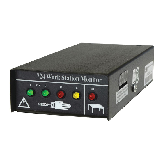
- Page 1 Workstation Monitor 724 ™ User’s Guide...
-
Page 2: Table Of Contents
Dual Conductor Remote Input Jack 733 ........17 ™ 10 Installation of Dual Conductor Remove Input Jack 733 ......18 11 Verification Procedure for the Workstation Monitor 724 ......18 12 Specifications ..................22 13 Parts Included ..................22 14 Required Accessories and Optional Available Parts ........ 23... -
Page 3: Safety Information
Surfaces Grounding Systems. If the equipment is used in a manner not specified in these instructions, the protection provided by the equipment may be impaired. Use in any other application has not been evaluated by 3M and may lead to an unsafe condition. - Page 4 Workstation Monitor 724 or its power supply outdoors in wet/humid ™ environments. • Do not use the Workstation Monitor 724 or its power supply outside of the operating conditions listed in this user guide. • Always follow instructions for installation as stated in these user instructions.
-
Page 5: Environmental Conditions
NOTE: This equipment has been tested and found to comply with the limits for a Class B digital device, pursuant to Part 15 of the FCC Rules. These limits are designed to provide reasonable protection against harmful interference in a residential installation. This equipment generates, uses and can radiate radio frequency energy and, if not installed and used in accordance with the instructions, may cause harmful interference to radio communications. -
Page 6: Theory Of Operation
The Workstation Monitor 724 employs two selectable test voltages (9 and 16 volts) and resistance limits (10 Megohms and 35 Megohms). It also monitors the grounding of up to two 3M work surfaces. The Workstation Monitor 724 contains a current-limiting resistor, through one side of the wrist... - Page 7 If the resistance of the wrist strap loop is higher than the selected range (10 Megohms or 35 Megohms) on the Workstation Monitor 724, an (OK) wrist strap green lamp (1 or 2) extinguishes, and a high wrist strap red lamp (H) illuminates with an audible alarm.
- Page 8 Workstation Monitor 724 illustrates the level the 3M Workstation Monitor 724. ™ of voltage that will appear on the operator under various resistance conditions. Voltage on Operator when connected to the Workstation Monitor 724 9V-10 9V-35 16V-10 16V-35 Condition...
- Page 9 3.7 Megohms the work surface high red lamp (M) will illuminate and the alarm will activate if selected. 2380 Mat Cord (without resistor) can also be used with the 724 Workstation Monitor It can be used when the surface resistance threshold of 3.7...
-
Page 10: Installation Of 3M ™ Workstation Monitor 724
(Figure 5B). Continue with step (2h). g) Attach the tinned Workstation Monitor 724 ground wire to the ground terminal of the two-wire connector by inserting the tinned end into opening and securing with screwdriver (Figure 5A). -
Page 11: Installation Of 3M Workstation Monitor 724 Without Work Surface Ground Monitoring
SECTION 3 Installation of 3M Workstation Monitor 724 without Work Surface Ground Monitoring Wire Attachments and Grounding – See Figure 12 for complete drawing of Workstation Monitor 724 wire connections. - Page 12 ™ • If you are grounding through the AC adapter, perform Step (3f.) • If you are grounding through the Workstation Monitor 724 ground ..wire, perform Step (3g.) Attach the tinned ground wire of the AC adapter to the ground terminal of the two-wire connector by inserting into opening and securing with screwdriver (Figure 5B).
- Page 13 Figure 7B – Grounding 3M Workstation Monitor Figure 8 – Inserting two-wire connector into rear of ™ 724. Workstation Monitor 724. ™ Figure 9 – Inserting 3M Dual Conductor Remote ™ Input Jack plug into rear of 3M Workstation Monitor ™ 724.
-
Page 14: Selection Of Test Voltage And Resistance Limit
Select the desired resistance and voltage limit by moving the appropriate slide switch (with screwdriver) on the side of the Workstation Monitor 724 to the desired position (Figure 2). -
Page 15: Wrist Strap Connection
Section 11). The Workstation Monitor ™ Ground When not using work station monitoring Ground feature, connect 724 is ready for use. Conductive work surface wire Work Surface to ground. Figure 12 – 3M Workstation Monitor 724 wire ™ connection diagram for single work station. -
Page 16: Fault Conditions
SECTION 7 Fault Conditions (Refer to Figure 3) Red Wrist Strap Lamp (H) Accompanied by an Audible Alarm This indicates that a high resistance condition Note: The operators may complain that the alarm is sounding too often until (greater than 10 Megohms or 35 Megohms) they learn to adjust the wrist band to exists for an operator or wrist strap assembly. -
Page 17: Standby Jack 3057
Workstation Monitor ™ 724 will illuminate upon connection. The low yellow lamp (L) will slowly flash if the standby jack is grounded. It can be grounded by attaching a ground wire to the screws or back plate. It can also be grounded if the plate is attached to a grounded metal surface. -
Page 18: Installation Of Dual Conductor Remove Input Jack 733
SECTION 11 Verification Procedure for the Workstation Monitor 724 The Workstation Monitor 724 cannot be recalibrated after the initial factory calibration. However, the following steps can be used to determine if the Workstation Monitor 724 is operating within its specifications. - Page 19 4.3 Megohms – Red work surface lamp (M) ON. Disconnect the cords from the RSB. g) Connect the ring terminal end of the Workstation Monitor 724 ground wire to the metal snap of the Monitor/Table Mat Cord 2380D. The red work surface lamp (M) should now be OFF.
-
Page 20: Wrist Strap
Connect the two-wire cable with 3.5 mm phone plug into the #1 input of the 3M Dual Conductor Remote Input Jack 732 and attach the other end ™ to the RSB. Set the resistance as follows and observe the 3M Workstation ™ Monitor 724 output: 1.3 Megohms –... - Page 21 Connect the two-wire cable with 3.5 mm phone plug into the #1 input of the 3M Dual Conductor Remote Input Jack 732 and attach the other end ™ to the RSB. Set the resistance as follows and observe the 3M Workstation ™ Monitor 724 output: 1.3 Megohms –...
-
Page 22: Specifications
1 ea. 3M Ground Cord ™ 1 ea. 3M Monitor/Table Mat Cord 2380D 1 ea. Workstation Monitor 724 ™ 1 ea. Two-Wire Connector 1 ea. Dual Conductor Remote Input Jack 732 4 ea. Mounting Screws 1 ea. AC Adapter (North America Power Supply). -
Page 23: Required Accessories And Optional Available Parts
SECTION 14 Required Accessories and Optional Available Parts Model No. Description Size 4720 Dual Conductor Wrist Band, Blue (ground cord not included) Adjustable ™ 2368 Dual Conductor Fabric Wrist Band Adjustable ™ 2381 Dual Conductor Metal Wrist Strap* Small ™ 2382 Dual Conductor Metal Wrist Strap* Medium... -
Page 24: Workstation Monitor
Only accessories, optional parts and replacement parts supplied or specified by 3M Company shall be used with this product. Use only a clean dry cloth to clean the 3M Workstation Monitor 724. ™ WEEE Statement The following information is only for EU-members States: The mark shown to the right is in compliance with Waste Electrical and Electronic Equipment Directive 2002/96/EC (WEEE). -
Page 25: Warranty
3M’s option, to replace or repair the 3M product or refund the purchase price of the 3M product. Except where prohibited by law, 3M will not be liable for any indirect, special, incidental or consequential loss or damage arising from this 3M product, regardless of the legal theory asserted.
Need help?
Do you have a question about the Workstation Monitor 724 and is the answer not in the manual?
Questions and answers