Table of Contents
Advertisement
Quick Links
Download this manual
See also:
User Manual
Advertisement
Table of Contents

Related Manuals for Asus V-Series P5G965


Summary of Contents for Asus V-Series P5G965
- Page 1 E2849 V-Series ASUS PC (Desktop Barebone) Installation manual...
-
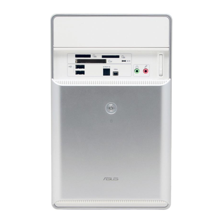
Page 2: Front Panel Features
Front panel features 5.25-inch drive bay cover 3.5-inch drive bay cover Headphone port Microphone port USB 2.0 ports* HDD LED Power button Reset button NOTE: *Some models may have two additional USB 2.0 ports and/or one IEEE 1394a port. Rear panel features NOTE: The rear panel ports and their locations may vary, depending on the model of your system. -
Page 3: Internal Components
Front panel cover 5.25-inch optical drive bays Floppy disk drive bay Hard disk drive bay NOTE: *Refer to the system User Guide for motherboard details. • 8-channel Power supply unit Chassis fan slot ASUS motherboard* Expansion slot metal brackets Installation manual... -
Page 4: Selecting The Voltage
Selecting the voltage The system’s power supply unit has a 115 V/230 V voltage selector switch located beside the power connector. Use this switch to select the appropriate system input voltage according to the voltage supply in your area. If the voltage supply in your area is 100-127 V, set the switch to 115 V. -
Page 5: Installing A Cpu
Installing a CPU Installing an Intel Pentium ® Locate the CPU socket on the motherboard. Press the load lever with your thumb (A), then move it to the left (B) until it is released from the retention tab. CAUTION. To prevent damage to the socket pins, do not remove the PnP cap unless you are installing a CPU. -
Page 6: Installing The Cpu Fan And Heatsink Assembly
Installing an AMD CPU Locate the CPU socket, then lift the socket lever to a 90º angle. Install the CPU to the socket, making sure that the CPU corner with the gold triangle matches the socket corner with a small triangle. Push down the socket lever to secure the CPU. - Page 7 Installing an AMD CPU heatsink and fan Place the heatsink on top of the installed CPU. IMPORTANT. Make sure that the fan and heatsink assembly perfectly fits the retention mechanism module base; otherwise you can not lock the retention bracket. Attach one end of the retention bracket to the retention module base. Attach the other end of the retention bracket (near the retention bracket lock) to the retention module base until it clicks in place.
-
Page 8: Installing A Dimm
Installing a DIMM Locate the DIMM sockets in the motherboard. Unlock a DIMM socket by pressing the retaining clips outward. Align a DIMM on the socket such that the notch on the DIMM matches the break on the socket. Push the DIMM to the socket until the retaining clips snap inward. CAUTION: •... -
Page 9: Installing Storage Drives
Installing storage drives Optical drive Place the chassis upright, then remove the upper 5.25” drive bay metal plate cover. Insert the optical drive to the bay, then carefully push the drive until its screw holes align with the holes on the bay. -
Page 10: Removing The Bay Covers And Reinstalling The Front Panel Assembly And Side Cover
For SATA HDD: Connect the SATA signal and power plugs to the connectors at the back of the drive. For IDE HDD: Connect the IDE and power plugs to the connectors at the back of the drive. Removing the bay covers and reinstalling the front panel assembly and side cover If you installed an optical and/or floppy disk drive, remove the bay cover(s) on the front panel assembly before reinstalling it to the chassis.
Need help?
Do you have a question about the V-Series P5G965 and is the answer not in the manual?
Questions and answers