Asus PC (Desktop Barebone) P1-P5945G Installation Manual
Asus asus pc (desktop barebone) installation manual
Hide thumbs
Also See for PC (Desktop Barebone) P1-P5945G:
- User manual (92 pages) ,
- User manual (92 pages) ,
- Installation manual (80 pages)

Related Manuals for Asus PC (Desktop Barebone) P1-P5945G


Summary of Contents for Asus PC (Desktop Barebone) P1-P5945G
-
Page 1: Installation Manual
P1-P5945G/P2-P5945G ASUS PC (Desktop Barebone) Installation Manual Download the latest manual from the ASUS website: www.asus.com... -
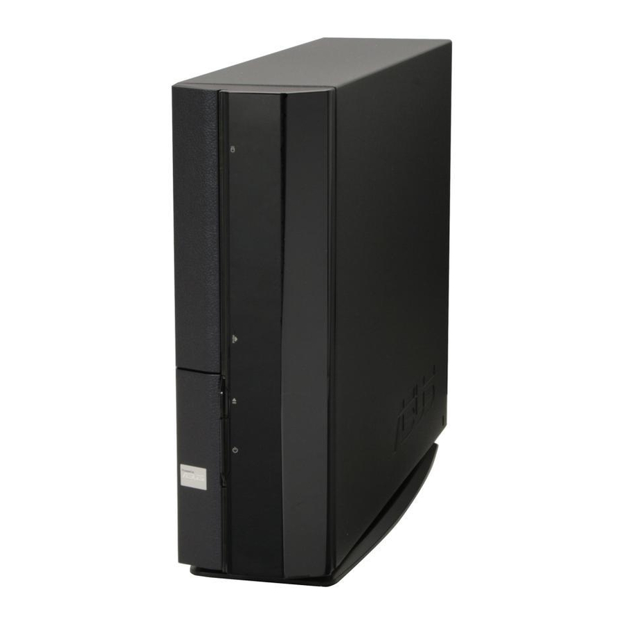
Page 2: Front Panel Features
Front panel features Close Front panel features Open Reset button MS/MS Pro card slot CompactFlash slot SD/MMC card slot 4-pin IEEE 1394 port USB 2.0 ports Headphone port Microphone port * The system’s power supply unit has a 115 V/230 V voltage selector switch located near the power connector. Use this switch to select the correct system input voltage according to the voltage supply in your area. -
Page 3: Internal Components
Removing the cover Remove the cover screws. Keep the screws for later use. Pull the cover slightly toward the rear panel. Lift the cover, then set aside. ASUS motherboard DIMM sockets LGA775 socket (under the CPU fan and heatsink assembly) -
Page 4: Removing The Front Panel Cover
Removing the front panel cover Lift the front panel cover hooks outward. Carefully remove the front panel cover, then set it aside. Removing the storage drive assembly Lay the system on its side, then locate and remove three storage drive assembly screws. Removing the CPU fan and heatsink Disconnect the CPU fan cable. -
Page 5: Installing The Cpu
Installing the CPU Unlock the load lever, then lift to a 90º-100º angle. Retention tab Load lever Install the CPU. The CPU fits in only one orientation. Reinstall the CPU fan and heatsink assembly, then reconnect the CPU fan cable to the CPU fan connector on the motherboard. Refer to the instructions in the previous section for details. -
Page 6: Installing An Expansion Card
Installing an expansion card Lift the PCI riser card assembly to remove. Insert the card connector to the slot, then press the card firmly until it fits in place. Secure the card with a screw. Installing optical and storage drives Turn the storage drive assembly upside down with the 3.5-inch bay on top of the 5.25-inch bay. -
Page 7: Reinstalling The Storage Drive Assembly
Reinstalling the storage drive assembly Before reinstalling the storage drive assembly, connect the IDE/SATA and power plugs to the IDE/SATA and power connectors at the back of the drives. Connect the black plug of the IDE cable to the optical drive, then the gray plug to the hard disk drive. -
Page 8: Reinstalling The Cover
Reinstalling the front panel cover Insert the front panel cover tabs to the holes at the right side of the chassis, then close. Insert the front panel cover hooks to the chassis tabs until the front panel cover fits in place. -
Page 9: Manuel D'installation
P1-P5945G/P2-P5945G ASUS PC (Système barebone) Manuel d’installation Téléchargez les derniers manuels depuis le site web d’ASUS: www.asus.com. - Page 10 Caractéristiques de la façade Fermé Caractéristiques de la façade Ouvert Bouton Reset Slot pour cartes MS/MS Pro Slot pour cartes CompactFlash Slot pour cartes SD/MMC Port IEEE 1394 4 broches Ports USB 2.0 Port Casque Port Microphone *L’alimentation du système est équipée d’un sélecteur de tension 115 V/230 V situé près du connecteur d’alimentation.
-
Page 11: Composants Internes
Enlever le capot Enlevez les deux vis. Conservez les vis pour un usage ultérieur. Tirez légèrement le panneau vers l’arrière. Soulevez le capot, puis basculez-le. Carte mère ASUS Sockets DIMM Socket LGA775 (sous le système de refroidissement du CPU) Système de refroidissement du... - Page 12 Retirer le capot de la façade Levez les crochets du capot avant vers l’extérieur. Retirez avec précaution le capot, puis mettez-le de côté. Retirer l ’ensemble de stockage Posez le système sur le côté, puis localisez et retirez les trois vis de l’ensemble de stockage.
- Page 13 Installer un CPU Soulevez le levier dans la direction de la flèche à un angle de 90º-100º . Onglet de rétention Levier Installez le CPU. Le CPU ne peut être placé que dans un seul sens. Réinstallez l’ensemble dissipateur/ventilateur du CPU, puis reconnectez le câble du ventilateur CPU au connecteur de la carte mère marqué...
-
Page 14: Installer Une Carte D'extension
Installer une carte d’extension Soulevez l’ensemble PCI Riser Card pour le retirez du châssis. Insérez le connecteur de la carte dans le slot et pressez jusqu’à ce que la carte soit en place. Sécurisez la carte avec une vis. Installer un lecteur optique ou de stockage Placez l’ensemble de stockage de façon à... - Page 15 Réinstaller l’ensemble de stockage Avant de réinstaller l’ensemble de stockage, connectez les prises IDE / SATA et d’alimentation aux connecteurs IDE / SATA et d’alimentation situés à l’arrière des lecteurs. Connectez la prise noire du câble IDE au lecteur optique, puis la prise grise au disque dur.
- Page 16 Réinstaller le capot de la façade Insérez les onglets du capot dans les ouvertures situées à droite du châssis, puis refermez-le. Insérez les crochets du capot de la façade dans les onglets du châssis jusqu’à ce que le capot soit bien en place. Réinstaller le panneau Installer le panneau sur le châssis en vous assurant que les onglets du panneau soient bien alignés sur les rails du châssis.
- Page 17 P1-P5945G/P2-P5945G 華碩個人電腦(桌上型準系統) 安裝手冊 請至華碩網站下載最新的產品使用手冊 www.asus.com...
- Page 18 前面板功能 外觀功能 前面板功能 內部連接埠 Reset 按鈕 MS/MS Pro 記憶 卡插槽 CompactFlash 記憶 卡插槽 SD/MMC card 記憶 卡插槽 4-pin IEEE 1394 � � USB 2.0 � 耳機 麥克風 * 電源供應器插座旁有一個電壓選擇開關,你可以利用這個開關切換到適合您所在區域所使用的電壓值。 若您所在區域提供電壓為 100-127V,請切換到 115V;若您所在區域提供電壓為 200-240V,請切換到 230V。 光碟機退出鈕 硬碟指示燈 光碟機插槽 輕壓一下打開 I/O 外蓋 電源按鈕...
- Page 19 內部組件 5.25 吋裝置插槽及3.5 吋硬碟機模 組支架 前面板 電源供應器 PCI 轉接卡模組(安插在主機板的 PCI 插槽) 打開機殼 鬆開機身後方的二顆機殼固定螺絲,並暫置於一旁。 將機殼小心地從機身後方推出。 取出機殼並暫置於一旁。 主機板 DIMM 插槽 LGA775 CPU 插座 (位於風扇的 下方) CPU 風扇 安裝手冊...
- Page 20 移除前面板 將前面板左側的三個固定卡榫往外 扳開。 移除儲存裝置模組 將主機平躺在桌面上,移除儲存裝 置支架的三顆固定螺絲。 移除 CPU 風扇 1. 移除 CPU 風扇電源線。 鬆 開 C P U 風 扇 的 四 顆 固 定 螺 絲,。 取出儲存裝置支架並暫置於一旁。 取出 CPU 風扇並暫置於一旁。 安裝手冊...
- Page 21 安裝 CPU 將固定扳手扳開����1���。 將固定扳手扳開����1���。 ���1���。 固定扣 回定扳手 安裝 CPU �插槽上。��� CPU � 安裝 CPU �插槽上。��� CPU � 能以單一方向正確地安裝到主機板 上的插槽。 裝回 CPU 風扇並接回風扇電源線。���前面小�的��。 裝回 CPU 風扇並接回風扇電源線。���前面小�的��。 安裝記憶體模組 �先找到主機板上的記憶體模組插 槽。 將記憶體模組插槽兩端的白色固定 卡榫扳開。 將記憶體模組的金手指對齊記憶體 模組插槽的溝槽,將記憶體模組插 入插槽中,若無錯誤,插槽兩端的 白色卡榫會因記憶體模組置入而自 動扣到記憶體模組兩側的凹孔中。 �。 將 CPU 安裝�的上���,並移 將 CPU 安裝�的上���,並移 除 CPU 安裝�上的保護�。 將上����上,接��將固定扳 將上����上,接��將固定扳 手朝原方向推回,並扣於固定扣之 上。 扳開二端的白 安裝手冊...
- Page 22 安裝擴充卡 將 PCI 轉接卡模組取出。 將擴充卡安裝在子卡插槽上,並鎖 上一顆固定螺絲。 安裝光碟機及硬碟機 將儲存裝置模組反轉過來,使硬碟插槽在上方,光碟機插槽在下方。 將光碟機反向裝入光碟機插槽中,並在二側各鎖上二顆固定螺絲。 接�再將硬碟機反向裝入硬碟插槽中,同樣在二側各鎖上二顆固定螺絲。��� 硬碟後端接頭需與光碟機後端接頭位在同一側。 移除您欲安裝插槽所對應的金屬擋 板。 將 PCI 轉接卡模組裝回主機內, ���是否正確安插在主機板的 PCI 插槽上。 安裝手冊...
- Page 23 裝回儲存裝置模組 裝回儲存裝置模組之前,請��� �������� ���������裝置������ ��� �������� ���������裝置������ �將 I D E 排線的黑色接頭連接�光碟機,灰色接頭連接硬碟機。若您使�� SATA 硬碟,�連接 SATA 排線� SATA 硬碟。 連接 4�pin 電源接頭�裝置後方的電源接頭。 裝回儲存裝置模組。 鎖上三顆固定螺絲。 安裝腳座 取出腳座並將腳座的卡榫對準機殼 底部的孔。 若要移除腳座,請��腳座往機殼�方推出,鬆開卡榫�即可取下� �������� ���������裝置������ ���裝置������ � 順�箭頭方向輕推,使腳座正確固 定在機殼底部。 安裝手冊 若您使��...
- Page 24 裝回前面板 將前面板�側卡榫對準機身的卡 �側卡榫對準機身的卡 溝小心地裝入,然後輕輕地闔 上。 確��一側的卡榫�確�固定在 確��一側的卡榫�確�固定在 主機上 裝回機殼 將機殼裝回,���機殼前方的卡榫��對準機身前方的卡溝。 將機殼裝回,���機殼前方的卡榫��對準機身前方的卡溝。 將機殼從機身後方往前方推入,並確�固定在機身上。 鎖上二顆固定螺絲。 鎖上二顆固定螺絲。 安裝手冊...
- Page 25 P1-P5945G/P2-P5945G 華碩個人電腦(桌上型準系統) 安裝手冊 請至華碩網站下載最新的產品用戶手冊 www.asus.com...
- Page 26 前面板功能 外觀功能 前面板功能 內部連接接口 Reset 按� MS/MS Pro 存 存 儲卡�� CompactFlash 存儲卡�� SD/MMC card 存儲卡�� 4-pin IEEE 1394 �� USB 2.0 �� 耳機 麥克風 * 電源供應器�座旁有一個電壓選擇開關,你可以利用這個開關切換到適合您所在區域所使用 的電壓值。若您所在區域提供電壓為 100-127V,請切換到 115V;若您所在區域提供電壓為 200-240V,請切換到 230V。 光���� ���� ��� 硬���� ���� ��� 光��� ��� ��...
- Page 27 內部組件 5.25 吋設備插槽及3.5 吋硬盤模塊 支架 前面板 電源供應器 P C I 轉接卡模塊(安插在主板的 PCI 插槽) 打開�� �� 鬆開�身後方的二顆����������於��� ����������於��� 將�������身後方��� �������身後方��� �����身後方��� 取������於��� �����於��� ���於��� 主板 DIMM 插槽 LGA775 CPU 插座 (位於風扇的 下方) CPU 風扇 ��������於��� 安裝手冊...
- Page 28 去�前面板 �前面板 將前面板左側的三個��卡榫往外 扳開� 去�存儲設備模塊 將主�平躺在桌面上�去�存儲設 備支架的三顆����� 去� CPU 風扇 去� CPU 風扇電源線� 鬆 開 C P U 風 扇 的 四 顆 � � � ��� 取�存儲設備支架���於��� 取� CPU 風扇���於��� 安裝手冊...
- Page 29 安裝 CPU 將��扳手扳開至���1���� 將��扳手扳開至���1���� ���1���� 固定扣 回定扳手 安裝 CPU 至插槽上���� CPU 安裝 CPU 至插槽上���� CPU 只能以單�方向正確�安裝到主板 上的插槽� 裝回 CPU 風扇�接回風扇電源線�請��前面��的��� 裝回 CPU 風扇�接回風扇電源線�請��前面��的��� 安裝內存� 內存� 請先找到主板上的內存�插槽� 將內存�插槽兩端的白色��卡 榫扳開� 將內存�的金手指對齊內存�插 槽 的 溝 槽 � 將 內 存 � 插 入 插 槽 中�若無錯誤�插槽兩端的白色...
- Page 30 安裝��卡 ��卡 卡 將 PCI 轉接卡模塊取�� 模塊取�� 取�� 將��卡安裝在�卡插槽上��� ��卡安裝在�卡插槽上��� 卡安裝在�卡插槽上��� 上�顆����� 安裝��及硬盤 ��及硬盤 及硬盤 硬盤 將存儲設備模塊�轉����硬盤插槽在上方���插槽在下方� 存儲設備模塊�轉����硬盤插槽在上方���插槽在下方� �轉����硬盤插槽在上方���插槽在下方� 將���向裝入��插槽中��在二側��上二顆����� ���向裝入��插槽中��在二側��上二顆����� �向裝入��插槽中��在二側��上二顆����� ��插槽中��在二側��上二顆����� 接�再將硬盤�向裝入硬盤插槽中���在二側��上二顆��������硬 硬盤�向裝入硬盤插槽中���在二側��上二顆��������硬 �向裝入硬盤插槽中���在二側��上二顆��������硬 盤後端接�����後端接�位在��側� 後端接�����後端接�位在��側� ��後端接�位在��側� 去���安裝插槽�對應的金�� 去���安裝插槽�對應的金�� ���安裝插槽�對應的金�� 板� 將 PCI 轉接卡模塊裝回主�內� ���是否正確安插在主板的 P C I 插槽上�...
- Page 31 裝回存儲設備模塊 存儲設備模塊 裝回������������� �������� ����������������� ������������� �������� ����������������� ������� �������� ����������������� �� �������� ����������������� 請將 IDE 排線的黑色接�連接至����色接�連接硬盤�若��用 �A�A 硬盤�請連接 �A�A 排線至硬盤� 連接 4�pin 電源接�至設備後方的電源接�� 設備後方的電源接�� 裝回存儲設備模塊� 存儲設備模塊� � �上三顆����� 安裝腳座 取�腳座�將腳座的卡榫對準�� 底部的孔� 若要移除腳座����腳座往����������������� ����������������� �������� ����������������� ����������� � ����色接�連接硬盤�若��用 �A�A ��色接�連接硬盤�若��用...
- Page 32 裝回前面板 將前面板�側卡榫對準�身的卡 �側卡榫對準�身的卡 溝���裝入�然後輕輕�闔 上� 確���側的卡榫�確���在 確���側的卡榫�確���在 主�上 裝回�� �� 將��裝回������前方的卡榫��對準�身前方的卡溝� 將��裝回������前方的卡榫��對準�身前方的卡溝� 將����身後方往前方�入��確���在�身上� �上二顆����� �上二顆����� 安裝手冊...
- Page 33 P1-P5945G/P2-P5945G ASUS PC (デスク トップ ベアボーン) インストールマニュアル 最新のマニュアルをASUSのWebサイ トからダウンロードしてください : www.asus.com.
- Page 34 フロントパネル 閉じた状態 フロントパネル 開けた状態 リセッ トボタン MS/MS Pro カード スロッ ト CompactFlash スロッ ト SD/MMC カード スロッ ト 4ピン IEEE 1394 ポート USB 2.0 ポート ヘッドフォンポート マイクポート * システムの電源には、 電源コネクタの側に 115 V/230 V 電圧セレクタスイッチがあります。 このスイッチを使っ て、 ご利用地域の電圧に合わせて適切なシステム入力電圧を選択します。 光学ドライブ イジェクトボタン HDD LED 光学ドライブベイ...
- Page 35 内部コンポーネント 5.25インチ 光学ドライブと 3.5インチHDDケージ フロントパネルカバー 光学ドライブロック PCI カードライザーブラケッ ト (マ ザーボードのPCIスロッ トに接続) カバーの取外し カバー用ネジを取り外します。 ネジは後で使用しますので、 紛失しないで下さい。 カバーをリアパネルの方向に引きます。 カバーを持ち上げて脇に置いておきます。 ASUS マザーボード DIMM ソケッ ト LGA775ソケッ ト (CPU ファンおよび 放熱板の下) CPU 用ファンおよび放熱板 インストールマニュアル...
- Page 36 フロントパネルカバーを取り外す フロントパネルカバーのフックを外 します。 フロントパネルカバーを外します。 記憶ドライブを取り外す システムを図のように置き、 記憶ド ライブを固定している3つのネジ を外します。 CPUファンとヒートシンクを取り外す CPU 用ファンケーブルを外します。 CPUファンとヒートシンクを固定し ているネジをゆるめます。 記憶ドライブを取り外します。 CPUファンとヒートシンクを持ち上 げ、 外します。 インストールマニュアル...
- Page 37 CPU の取付け ロードレバーのロックを外し、 90° 〜100° 上げます。 装着レバー 受け側のツメ CPU をはめます。 CPU は一方向の みフィッ トします。 CPUファンとヒートシンクを取り付け、 CPUファンケーブルをCPUファンコネクタ に接続します。 詳細は前のセクションをご覧ください。 DIMM の取付け マザーボードの DIMM ソケッ トの位 置を確認します。 固定クリップを外側に押して、 DIMM ソケッ トを外します。 DIMM とソケッ トの溝を合わせて DIMM をソケッ トにはめます。 ロードプレートを上げ、 ソケッ トキ ャップを外します。 装着プレートを閉じて、 装着レバー をロックします。...
- Page 38 拡張カードの取付け PCI ライザーカードを上に引き、 取 り外します。 3. カードコネクタをスロッ トには めて、 カードが止まるまでしっ かり押しこみます。 カードをネ ジで固定します。 光学ドライブと記憶ドライブを取り付ける 図のように記憶ドライブを、 3.5インチベイが5.25インチベイの上になるように置 きます。 光学ドライブを上下逆さまの状態で5.25インチベイに入れ、 2つのネジで固定し ます。 HDDを上下逆さまの状態で3.5インチベイに入れ、 2つのネジで固定します。 使用するスロッ トに対応する金属 製カバーを外します。 PCI ライザーカードを再び取り付 け、 ライザーカードコネクタがPCI スロッ トにしっかりはまっているこ とを確認します。 インストールマニュアル...
- Page 39 記憶ドライブを再び取り付ける 作業の前に、 IDE / SATA と電源プラグを各コネクタに接続します。 IDE ケーブルの黒いプラグを光学ドライブに、 グレーのプラグをHDDに接続しま す。 SATA HDDがある�合は、 SATA ケーブルをSATA HDに接続します。 SATA HDDがある�合は、 SATA ケーブルをSATA HDに接続します。 4ピン電源プラグを電源コネクタに接続します。 記憶ドライブをケースに取り付けます。 記憶ドライブをネジで3ケ所固定します。 フッ トスタンドを取り付ける フッ トスタンドのフックをケースの 穴に合わせます。 フッ トスタンドを外す�合は、 ロックを上げ、 ケースから外れるまでフッ トスタンドをリ アパネルの方向に動かします。 フッ トスタンドをロックされるまで 矢印の方向に動かします。 インストールマニュアル...
- Page 40 フロントパネルカバーを再びインストールする フロントパネルカバーのタブをケ ースの右サイドの穴に入れ、 閉じま す。 フロントパネルカバーのフックを ケースのタブにしっかり固定しま す。 カバーを再び取り付ける カバーをケースに取り付けます。 カバーのタブをシャーシのレールにしっかり合 わせます。 カバーをフロントパネルの方向にスライドさせます。 2つのネジでカバーを固定します。 インストールマニュアル...
- Page 41 P1-P5945G/P2-P5945G ASUS PC (데스크탑 베어본) 빠른 설치 가이드 최신 사용자 설명서 다운로드: www.asus.com...
- Page 42 전면부 사양 닫힌 상태 전면부 패널 사양 열린 상태 리셋 버튼 MS/MS Pro 카드 슬롯 CompactFlash 카드 슬롯 SD/MMC 카드 슬롯 4핀 IEEE 1394 포트 USB 2.0 포트 헤드폰 포트 마이크로폰 포트 * 시스템 전원 공급 유닛의 115 V/230 V 전압 셀렉터 스위치는 전원 커넥터 주변에 위치하고 있습니다. 이...
- Page 43 PCI 슬롯에 연결되어 있음) 커버 제거 커버 나사를 제거한 후, 잘 보관해 주십시오. 커버를 바깥 방향으로 밀어 주십시오. 커버를 들어 옆에 보관해 주십시오. ASUS 마더보드 DIMM 소켓 LGA775 소켓 (CPU 팬과 힛 싱크 조립 하단) CPU 팬 & 힛 싱크 조립...
- Page 44 전면부 패널 제거 전면부 패널 커버 걸쇠를 바깥 방 향으로 올려 주십시오. 전면부 패널 커버를 조심스럽게 제거한 후, 옆에 놓아 주십시오. 저장 장치 드라이브 제거 시스템을 옆으로 눕힌 후, 저장 장 치 드라이브의 나사 3개를 제거해 주십시오. CPU 팬과 힛 싱크 제거 CPU 팬...
- Page 45 CPU 설치 로드 레버의 잠금 장치를 풀고, 90°-100° 각도로 올려 주십시오. 리텐션 탭 CPU를 설치해 주십시오. CPU는 오직 한 방향으로만 설치 가능합 니다. CPU와 힛 싱크를 다시 설치하신 후, CPU 팬 케이블을 마더보드의 CPU 팬 커넥터에 연결해 주십시오. 자세한 설명은 이전 페이지의 설치 절차를 참고 해...
- Page 46 확장 카드 설치 PCI 라이저 카드를 제거해 주십시 오. 슬롯에 카드 커넥터를 장착한 후, 나사로 완전히 고정시켜 주십시 오. 옵티컬 & 저장 장치 드라이브 설치 5.25 인치 베이 위에 3.5 인치 베이가 위치하도록 저장 장치 드라이브를 거꾸 로 돌려 주십시오. 거꾸로...
- Page 47 저장 장치 드라이브 재설치 저장 장치 드라이브를 재설치 하기 전에, IDE/SATA 및 전원 플러그를 드라이브 후 면부에 위치한 IDE/SATA & 전원 커넥터에 연결해 주십시오. IDE 케이블의 검은색 플러그를 옵티컬 드라이브에 연결해 주시고, 회색 플러 그는 하드 디스크 드라이브에 연결해 주십시오. 만약 SATA HDD가 있다면, SATA 케이블을...
- Page 48 전면부 패널 커버 재설치 케이스 우측에 위치한 구멍에 전 면부 패널 커버 탭을 삽입한 후, 닫아 주십시오. 케이스 탭에 전면부 패널 걸쇠를 삽입해 주십시오. 커버 재설치 케이스에 커버를 설치해 주십시오. 커버의 탭이 케이스 레일에 올바르게 위 치했는지 확인해 주십시오. 커버를 전면부 패널 쪽으로 밀어 주십시오. 두...
- Page 49 P1-P5945G/P2-P5945G ASUS PC (Mini Masaüstü Bilgisayar) Kurulum Elkitabı ASUS web sitesinden en yeni kullan›m elkitab›n› indirin: www.asus.com.
- Page 50 Ön panel özellikleri Kapat Ön panel özellikleri Aç S›f›rlama dü¤mesi MS/MS Pro kart yuvas› CompactFlash yuvas› SD/MMC kart yuvas› 4-pimli IEEE 1394 portu USB 2.0 giriflleri Kulakl›k girifli Mikrofon girifli * Sistem güç besleme ünitesinde güç konektörünün yan›na yerlefltirilen 115 V/230 V de¤erinde voltaj seçme dü¤mesi bulunmaktad›r.
- Page 51 Kapa¤›n ç›kar›lmas› Kapak vidalar›n› sökün. Vidalar› ileride kullanmak için saklay›n. Kapa¤› arka panele do¤ru yavaflça çekin. Kapa¤› kald›r›n, ard›ndan kenara koyun. ASUS anakart DIMM soketleri LGA775 soketi (CPU fan› ve ›s› alma komplesi alt›nda) CPU fan› ve ›s› alma komplesi...
- Page 52 Ön panel kapa¤›n›n ç›kar›lmas› Panel kapa¤› çengellerini d›flar›ya do¤ru kald›r›n. Ön panel kapa¤›n› dikkatli bir flekilde ç›kar›n, ard›ndan kenara koyun. Saklama sürücüsü komplesinin ç›kar›lmas› Sistemi yan taraf›na koyun, ard›ndan üç adet saklama sürücüsü montaj vidalar›n› bulun ve ç›kar›n. CPU fan›n›n ve ›s› al›c›n›n ç›kar›lmas› CPU fan kablosunun ba¤lant›s›n›...
- Page 53 CPU’nun tak›lmas› Yük kolunun kilidini aç›n, ard›ndan 90 - 100 aç› yapacak flekilde kald›r›n. Tutma sekmesi Yük kolu CPU’yu tak›n. CPU sadece bir yönde oturur. CPU fan›n› ve ›s› alma komplesini yeniden kurun, ard›ndan CPU fan kablosunu anakarttaki CPU fan konektörüne yeniden ba¤lay›n. Ayr›nt›lar için önceki bölümde verilen talimatlar bölümüne bak›n.
- Page 54 Geniflletme kart›n›n tak›lmas› Ç›karmak için PCI kald›rma kart› komplesini kald›r›n. Kart konektörünü yuvaya tak›n, ard›ndan yerine oturuncaya kadar karta düzgün bir flekilde bast›r›n. Kart› vidalar› kullanarak sabitleyin. Optik ve saklama sürücülerinin kurulmas› Saklama sürücüsü komplesinin 3.5 inçlik yuvay› kullanarak 5.25 inçlik yuvan›n üstünde üstünü...
- Page 55 Saklama sürücüsü komplesinin yeniden kurulmas› Saklama sürücü komplesini yeniden kurmadan önce, IDE / SATA ve güç tapalar›n› IDE / SATA’ye ve güç konektörlerini sürücülerin arkas›na ba¤lay›n. IDE kablosunun siyah renkteki fiflini optik sürücüye ba¤lay›n, ard›ndan gri renkteki fifli ise sabit disk sürücüsüne ba¤lay›n. SATA HDD'iniz varsa, SATA kablosunu SATA HD'ye ba¤lay›n.
- Page 56 Ön panel kapa¤›n›n yeniden tak›lmas› Ön panel kapa¤› sekmelerini flasenin sa¤ taraf›ndaki deliklere yerlefltirin, ard›ndan kapa¤› kapat›n. Ön panel kapa¤› çengellerini ön panel kapa¤› yerine oturuncaya kadar flase sekmelerine tak›n. Kapa¤›n yeniden tak›lmas› Kapa¤› flaseye tak›n. Kapak sekmelerinin flase raylar›na oturdu¤undan emin olun.
Need help?
Do you have a question about the PC (Desktop Barebone) P1-P5945G and is the answer not in the manual?
Questions and answers