Table of Contents
Advertisement
Advertisement
Table of Contents

Subscribe to Our Youtube Channel
Related Manuals for Labconco CentriVap 78110 Series


Summary of Contents for Labconco CentriVap 78110 Series
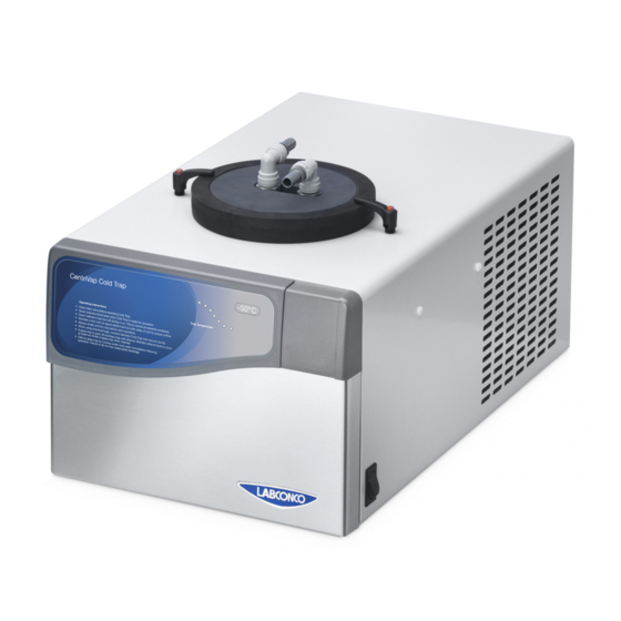
- Page 1 CentriVap Cold Traps Models 78110 Series 74600 Series 73850 Series...
- Page 2 Warranty Labconco Corporation provides a warranty to the original buyer for the repair or replacement of parts and reasonable labor as a result of normal and proper use of the equipment with compatible chemicals. Broken glassware and maintenance items, such as filters, gaskets, light bulbs, finishes and lubrication are not warranted.
-
Page 3: Table Of Contents
ABLE ONTENTS CHAPTER 1: INTRODUCTION Safety Symbols CHAPTER 2: PREREQUISITES Electrical Requirements Location and Exhaust Requirements Vacuum Pump Requirements Vacuum Line Traps Space Requirements CHAPTER 3: GETTING STARTED Unpacking Your CentriVap Cold Trap CentriVap Cold Trap Components Component Orientation & Hose Connections Electrical Connection Ground Wire Chemical Resistance of CentriVap Cold Trap Components... -
Page 5: Chapter 1: Introduction
Chapter 1: Introduction Congratulations on your purchase of a Labconco CentriVap Cold Trap. Models are available for operation on 115V or 230V. The CentriVap Cold Trap protects the vacuum pump by trapping moisture, vapors and corrosive fumes as they evaporate from the samples. The stainless steel trap is used for aqueous and organic applications. - Page 6 Chapter 1: Introduction It is important that you understand the warnings listed throughout this manual before you operate the CentriVap Cold Trap. Product Service 1-800-522-7658...
-
Page 7: Chapter 2: Prerequisites
Chapter 2: Prerequisites Before you install your CentriVap Cold Trap, you need to prepare your site for installation. You must be certain that the area is level and of solid construction. In addition, a means to exhaust the vacuum pump must be provided. An electrical source must be located near the installation site. -
Page 8: Electrical Requirements
Chapter 2: Prerequisites Electrical Requirements The CentriVap Cold Trap requires a dedicated electrical outlet. 115V (-50°C & -85°C) Models require a 15 Amp circuit breaker or fuse rated at 115V (60 Hz). 115V (-105°C) Models require a 20 Amp circuit breaker or fuse rated at 115V (60 Hz). -
Page 9: Vacuum Pump Requirements
NOTE: Several components within the CentriVap Cold Trap are made from stainless steel or other materials and can be degraded if exposed to acids. Contact Labconco before evaporating acids. Space Requirements Refer to Appendix B: Cold Trap Dimensions for dimensional drawings of the CentriVap Cold Traps. -
Page 10: Chapter 3: Getting Started
Chapter 3: Getting Started Now that the site for your CentriVap Cold Trap is properly prepared, you are ready to unpack, inspect, install, and test your CentriVap Cold Trap. Read this chapter to learn how to: Unpack and move your CentriVap Cold Trap. ... -
Page 11: Unpacking Your Centrivap Cold Trap
CentriVap Cold Trap. NOTE: Do not return goods without the prior authorization of Labconco. Unauthorized returns will not be accepted. If your CentriVap Cold Trap was damaged in transit, you must file a claim directly with the freight carrier. -
Page 12: Component Orientation & Hose Connections
Chapter 3: Getting Started Component Orientation & Hose Connections The relative position of the CentriVap Cold Trap and the vacuum pump is critical. The Cold Trap should always be placed before the vacuum pump. Air to cool the refrigeration system of the Cold Trap is drawn into the right side of the Cold Trap cabinet and exhausts out the left side of the cabinet. -
Page 13: Electrical Connection
EPDM C C D Rotor Shaft Hastelloy Valve Teflon Diaphragm vacuum pumps sold by Labconco have wetted parts either made O Rings Viton (Fluorocarbon) Fittings Polypropylene from PTFE or protected by PTFE coatings and are suitable for nearly all... -
Page 14: Solvent Safety Precautions
Chapter 3: Getting Started When using compounds in the CentriVap Cold Trap that are hostile to the materials of construction, it is imperative that the equipment is appropriately maintained. After each run, clean up all residues, spills and materials that might have splashed in the chamber. - Page 15 Chapter 3: Getting Started Do not store flammable or hazardous solvents within 12 inches (300 mm) of the CentriVap Cold Trap. IMPORTANT NOTE: The disposal of substances used in connection with this equipment may be governed by various Federal, State or local regulations.
-
Page 16: Chapter 4: Maintaining Your Centrivap Cold Trap
Chapter 4: Maintaining Your CentriVap Cold Trap Under normal operation, the CentriVap Cold Trap requires little maintenance. The following maintenance schedule is recommended. Before servicing the Cold Trap, disconnect electrical power. Special precautions must be observed if materials used in the CentriVap Cold Trap are known to be hazardous, toxic, radioactive or contaminated with biohazardous. - Page 17 9. Check the continuity of the protective earth between the ground terminal on the power inlet and a bare metal housing panel. Contact Labconco if there is no continuity. 10. Repair any defects to the surface where the CentriVap Cold Trap is installed.
-
Page 18: Chapter 5: Accessories For Your Centrivap Cold Trap
Chapter 5: Accessories for Your CentriVap Cold Trap The configuration of your CentriVap Cold Trap can be changed to accommodate your needs. You may wish to add a secondary trap to trap vapors exhausted from the vacuum pump. Read this chapter to learn how to: ... - Page 19 Chapter 5: Accessories for Your CentriVap Cold Trap The following accessories are available for the CentriVap Concentrator and Cold Trap System. PART # DESCRIPTION 7460900 Clear Canister - Accommodates inserts listed below 7814800 Acid Trap Insert 7814900 Moisture Trap Insert 7995600 Ammonia Trap Insert 7815000...
-
Page 20: Installing A Secondary Chemical Trap
Use a Geiger counter to monitor the pump exhaust. NOTE: This radiochemical cartridge does not meet NRC filter design recommendations. After operating, properly dispose of all hazardous materials in compliance with all applicable codes. Labconco is not responsible for improper disposal of any materials. Product Service 1-800-522-7658... -
Page 21: Installing A Glass Trap In The Cold Trap
Chapter 5: Accessories for Your CentriVap Cold Trap Installing a Glass Trap in the Cold Trap An accessory Glass Trap is available for use in the Cold Trap for use when corrosive chemicals are used that could attack the stainless steel chamber of the Cold Trap. -
Page 22: Chapter 6: Troubleshooting
Chapter 6: Troubleshooting Refer to the following if your CentriVap Cold Trap fails to operate properly. If the suggested corrective actions do not solve your problem, contact Labconco for additional assistance. CAUTION: Disconnect power before corrective action is taken. PROBLEM... - Page 23 Chapter 6: Troubleshooting PROBLEM CAUSE CORRECTIVE ACTION No vacuum/poor vacuum Pump is not functioning Check pump by locating vacuum gauge properly closer to pump and close off rest of system. (cont.) Check pump oil for cloudiness or particles and change. If pump is faulty, seek authorized service or replace pump.
-
Page 24: Appendix A: Centrivap Cold Trap Components
Appendix A: CentriVap Cold Trap Components The following pages list components that are available for your CentriVap Cold Trap. The parts shown are the most common replacement parts. If other parts are required, contact Product Service. Product Service 1-800-522-7658... - Page 25 Appendix A: CentriVap Cold Trap Components CentriVap Cold Trap Components (-50°C Models) Item Quantity Part No. Description 7398100 Label 7394400 Printed Circuit Board 1302300 Switch 1327208 Circuit Breaker (115V) 1327204 Circuit Breaker (230V) 1333800 Power Cord Inlet 7437700 Compressor (115V) 7437701 Compressor (230V/50Hz) 7734402...
- Page 26 Appendix A: CentriVap Cold Trap Components Product Service 1-800-522-7658...
- Page 27 Appendix A: CentriVap Cold Trap Components CentriVap Cold Trap Components (-85°C Models) Item Quantity Part No. Description 7398100 Label 7394402 Printed Circuit Board Switch – Power 1302300 7474200 Timer (115V) 7474400 Timer (230V) Switch – Pressure 7431700 1360500 Valve Wire Assembly – Ground 7464600 1327207 Circuit Breaker (115V)
- Page 28 Appendix A: CentriVap Cold Trap Components Product Service 1-800-522-7658...
- Page 29 Appendix A: CentriVap Cold Trap Components CentriVap Cold Trap Components (-105°C Models) Item Quantity Part No. Description 7398100 Label 7394402 Printed Circuit Board Switch – Power 1302300 7474200 Timer (115V) 7474400 Timer (230V) Switch – Pressure 7431700 1360500 Valve Wire Assembly – Ground 7464600 1289315 Circuit Breaker (115V)
- Page 30 Appendix A: CentriVap Cold Trap Components Product Service 1-800-522-7658...
-
Page 31: Appendix B: Centrivap Cold Trap Dimensions
Appendix B: CentriVap Cold Trap Dimensions CentriVap Cold Trap (-50°C Models) Product Service 1-800-522-7658... - Page 32 Appendix B: CentriVap Cold Trap Dimensions CentriVap Cold Trap (-85°C Models) Product Service 1-800-522-7658...
- Page 33 Appendix B: CentriVap Cold Trap Dimensions CentriVap Cold Trap (-105°C Models) Product Service 1-800-522-7658...
-
Page 34: Appendix C: Centrivap Cold Trap Specifications
Appendix C: CentriVap Cold Trap Specifications This Appendix contains technical information about the CentriVap Cold Trap including specifications and environmental operating conditions. Electrical Specifications Nominal amperage for 115V/60Hz Cold Trap (-50° Models): 6.0A. Nominal amperage for 230V 50/60Hz Cold Trap (-50° Models): 2.5A. ... -
Page 35: Environmental Conditions
Appendix C: CentriVap Cold Trap Specifications Environmental Conditions Indoor use only. Maximum altitude: 6562 feet (2000 meters). Ambient temperature range: 41° to 104°F (5° to 40°C). Maximum relative humidity: 80% for temperatures up to 88°F (31°C), decreasing linearly to 50% relative humidity at 104°F (40°C).
Need help?
Do you have a question about the CentriVap 78110 Series and is the answer not in the manual?
Questions and answers