Table of Contents
Advertisement
Quick Links
Reflexomat Touch
03.09.2020 - Rev. A
RS 90/1 T, RS 150/1 T, RS 300/1 T, RS 400/1 T, RS 580/1 T
RS 90/2 T, RS 150/2 T, RS 300/2 T, RS 400/2 T, RS 580/2 T
external air T
GB
Operating manual
Original operating manual
Cooke Industries - Phone: +64 9 579 2185
Email: sales@cookeindustries.co.nz
Web: www.cookeindustries.co.nz
Advertisement
Table of Contents

Related Manuals for Reflex Reflexomat RS 90/1 T


Summary of Contents for Reflex Reflexomat RS 90/1 T
- Page 1 Reflexomat Touch 03.09.2020 - Rev. A RS 90/1 T, RS 150/1 T, RS 300/1 T, RS 400/1 T, RS 580/1 T RS 90/2 T, RS 150/2 T, RS 300/2 T, RS 400/2 T, RS 580/2 T external air T Operating manual Original operating manual Cooke Industries - Phone: +64 9 579 2185 Email: sales@cookeindustries.co.nz...
-
Page 2: Table Of Contents
13 Annex ..................23 7.3.1 Positioning ................10 7.3.2 Tank installation ..............10 13.1 Reflex Customer Service ............... 23 7.3.3 Connection to the facility system ........10 13.2 Conformity and standards ..............23 7.3.4 Connection to an external compressed air line ....11 13.3... -
Page 3: Notes On The Operating Manual
Reflex Winkelmann GmbH accepts no liability for any damage resulting from Personnel requirements failure to observe the information in this operating manual. In addition to the... -
Page 4: Description Of The Device
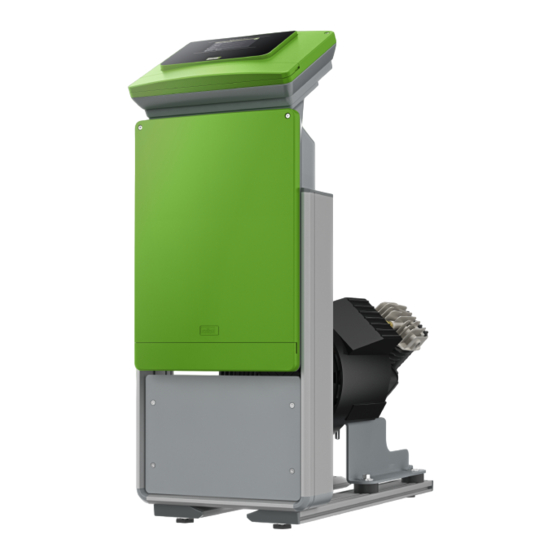
Description of the device Reflexomat with touch control and two compressors Description of the device Description The Reflexomat is a pressurisation station for heating and cooling water systems. The Reflexomat essentially comprises a controller and at least one expansion vessel. The additional connection of secondary vessels is optionally possible. The expansion vessel is fitted with a diaphragm to divide the vessel into an air space and a water space. -
Page 5: Type Code
I/O module for standard communication, see chapter 5 "I/O module Control unit (optional expansion module)" on page 6 . The control unit contains one or optionally two compressors "CO" and the "Reflex – Master-Slave-Connect for master controllers for maximum 10 Control Touch"... -
Page 6: O Module (Optional Expansion Module)
7 • All digital inputs and outputs can be set freely as option. Settings to be made by Reflex Customer Service, see chapter 13.1 "Reflex Customer Service" on page 23 Technical data Relay outputs of the I/O "Control Touch"... -
Page 7: Setting The Module Address
Default settings apply to software version V1.10 and higher. • All digital inputs and outputs can be set freely as option. The setting is carried out by Reflex Customer Service, see chapter 13.1 "Reflex Customer Service" on page 23 Location Signal... -
Page 8: Replacing The Fuses
Technical data Location Signal Message text Fault memory Priority Signal on the input triggers the following action evaluation entry OUTPUTS Changeover • Maximum pressure exceeded contact • "ER 10" message in the controller Changeover Switches in manual mode contact Switches in stop mode Switches with inputs 3,5,6 active Changeover Make-up fault... -
Page 9: Installation
DN40 1600 prerequisite for the making of warranty claims. 10 bar - 750 DN50 2185 – Have the Reflex Customer Service carry out commissioning and the annual maintenance. 10 bar - 1000 1000 DN65 2065 10 bar - 1500 1200... -
Page 10: Execution
Installation Execution Comply with the following notes regarding the installation of the primary vessel and the secondary vessels: ATTENTION Damage due to improper installation Additional device stresses may arise due to the connection of pipes or system equipment. • Ensure that pipes are connected from the device to the system without them being stressed or strained. -
Page 11: Connection To An External Compressed Air Line
See chapter "Terminal plan" for the solenoid valve electrical connection. For details regarding the switching of Reflexomats or in-line vessels and the dimensions of the expansion lines, please see the planning documents. More information is also provided in the Reflex Planning Guide. 7.3.3.2 Control unit connection •... -
Page 12: Fitting The Level Sensor
Preferably, you should use the Reflex Fillset with integrated system separator when using drinking water for make-up. If you don't use a Reflex Fillset, you must use an "ST" dirt trap with a mesh size ≥ 0.25 mm for the make-up. -
Page 13: Electrical Connection
Installation Electrical connection 7.5.1 Terminal plan, connection component DANGER Risk of serious injury or death due to electric shock. If live parts are touched, there is risk of life-threatening injuries. • Ensure that the system is voltage-free before installing the device. •... -
Page 14: Terminal Plan, Operating Unit
The following bus modules form part of the optional accessories available for interface communication. Note! If required, please contact the Reflex Customer Service for the protocol of the RS-485 interface, details of the connections and information about the accessories offered. 7.5.3.1 Connecting the RS-485 interface •... -
Page 15: Installation And Commissioning Certificate
Have the Reflex Customer Service carry out commissioning and be run only once. The settings can be changed or checked in the Customer menu the annual maintenance. after the start routine has terminated see chapter 13.1 "Reflex Customer Service" on page 23 . Checking the requirements for commissioning A three-digit PM code is assigned to the setting options. -
Page 16: Venting The Vessels
If null balancing is not successfully completed, you cannot commission the device. In this case, please contact Customer Service, see chapter 13.1 "Reflex Customer Service" on page 23 . Select the calculated minimum operating pressure and conform your entry with "OK". -
Page 17: Starting Automatic Mode
Operation Note! Starting Automatic mode Manual operations cannot be performed if safety-relevant parameters Automatic operation is executed as conclusion of the initial commissioning. The would be exceeded. Switching is then disabled. following prerequisites must be met for automatic operation: •... -
Page 18: Calibrating The Touch Screen
Controller Description 10.2 Calibrating the touch screen Code • With softening "Yes/'No" – If "Yes", continue with 031 • Shut off make-up "Yes/No" (if water capacity is exhausted) • Hardness reduction … °dH = GHactual – GHtarget • Soft water capacity –... -
Page 19: Default Settings
Message causes can be eliminated by the operator or a specialist workshop. If with "With water meter Yes". this is not possible, contact the Reflex Customer Service. Maximum make-up time 30 minutes Note! - Page 20 Replace the softening cartridges. "OK" • Time interval for replacement of the softening cartridge exceeded. I/O module fault • I/O module defective Inform Reflex Customer Service. – • Connection between option card and controller faulty. • Option card defective. EEPROM defective •...
-
Page 21: Maintenance
Note! Arrange for maintenance tasks must be carried out only by specialist Activating the device personnel or Reflex Customer Service. 11. Switch on the main switch. 12. Switch to Automatic mode. – Depending on the filling level and pressure, the "CO" compressor and 11.1... -
Page 22: Cleaning
– Press "Auto" on the controller's operator panel. Note! Clean all other installed dirt traps (in the Reflex Fillset, for example). 22 — English — 03.09.2020 - Rev. A Cooke Industries - Phone: +64 9 579 2185 Email: sales@cookeindustries.co.nz... -
Page 23: Disassembly
Conformity and standards Risk of burns on hot surfaces Hot surfaces in heating systems can cause burns to the skin. Device conformity declarations are available on the Reflex homepage. • Wait until hot surfaces have cooled down or wear protective safety www.reflex-winkelmann.com/konformitaetserklaerungen... - Page 24 Annex sag dr Installation and commissioning certificate - This device has been installed and commissioned in accordance with the instructions provided in the operating manual. The settings in the controller match the local conditions. Typ / Type: Fabr. Nr. / Serial-No. 24 —...
- Page 25 Reflex Winkelmann GmbH Gersteinstraße 19 59227 Ahlen, Germany +49 (0)2382 7069-0 +49 (0)2382 7069-9546 www.reflex-winkelmann.com Cooke Industries - Phone: +64 9 579 2185 Email: sales@cookeindustries.co.nz Web: www.cookeindustries.co.nz...
Need help?
Do you have a question about the Reflexomat RS 90/1 T and is the answer not in the manual?
Questions and answers