Table of Contents
Advertisement
Quick Links
ISO Registered Company
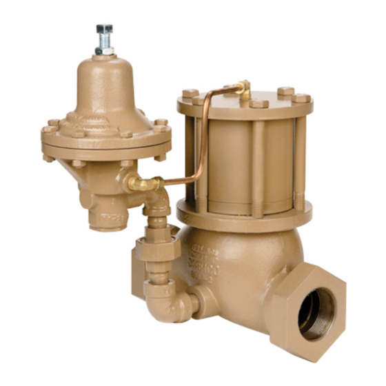
PILOT OPERATED PRESSURE RE DUC ING REGULATOR
. DESCRIPTION AND SCOPE
I
The POSR-2 is a pilot operated pressure reducing reg u la tor used to control downstream (P
1", 1-1/2", 2", 3" and 4" (DN25, 40, 50, 80, 100). The unit is suitable for steam service only. Refer to Technical
Bulletin POSR-2-TB for design conditions and selection recommendations. NOT RECOMMENDED FOR DEAD
END SERVICE.
II. INSTALLATION
A. General:
Do not dead end (no flow demand) downstream of POSR-2
if P
- Inlet Pressure is greater than max i mum allowable
1
outlet design pressure.
Spring Range
5-15 psig (0.34–1.03 Barg)
10–40 psig (0.69–2.8 Barg)
30–80 psig (2.1–5.5 Barg)
70–150 psig (4.8–10.3 Barg)
B. Piping the Valve:
1. An inlet block valve should always be in stalled.
2. If service application is continuous such that
shut down is not readily accomplished, it is
recommended that an inlet block valve, outlet
block valve, and a manual bypass valve be
installed.
3. Pipe unions are recommended for NPT
screwed in stal la tions to allow removal from
piping.
4. An outlet pressure gauge should be located
ap prox i mate ly ten pipe diameters down stream,
and within sight.
5. All installations should include a downstream
re lief device if the inlet pressure could exceed
the pressure rating of any downstream
equip ment or the maximum allowable outlet
pres sure rating of the unit.
INSTALLATION, OPERATION & MAINTENANCE MANUAL (IOM)
MODEL POSR-2
WARNING
Max. Allowable
Outlet Pressure
100 psig (6.9 Barg)
200 psig (13.8 Barg)
200 psig (13.8 Barg)
200 psig (13.8 Barg)
SECTION I
SECTION II
Recommended Piping Schematic for POSR-2
Installation of adequate overpressure pro tec tion is
recommended to pro tect the reg u la tor from overpressure
and all down stream equip ment from damage in the event
of regulator failure.
For welded installations, all internal trim parts, seals and
diaphragm(s) must be removed from reg u la tor body prior
to welding into pipeline. The heat of fusion welding will
dam age non-metallic parts if not re moved. NOTE: This does
not apply to units equipped with extended pipe nip ples.
6. Clean the piping of all foreign material in clud ing
chips, welding scale, oil, grease and dirt
before installing the regulator. Strainers are
recommended.
IOM-POSR-2
) pressure. Sizes are
2
FIGURE 1
CAUTION
CAUTION
02-20
Advertisement
Table of Contents

Related Manuals for cashco POSR-2


Summary of Contents for cashco POSR-2
- Page 1 SECTION I . DESCRIPTION AND SCOPE The POSR-2 is a pilot operated pressure reducing reg u la tor used to control downstream (P ) pressure. Sizes are 1", 1-1/2", 2", 3" and 4" (DN25, 40, 50, 80, 100). The unit is suitable for steam service only. Refer to Technical Bulletin POSR-2-TB for design conditions and selection recommendations.
-
Page 2: Principle Of Operation
1. The POSR-2 pilot obtains its operating me di um and allows the loading pres sure on the main from the main valve body inlet. Down stream valve’s piston to decay, allowing partial closing... - Page 3 Pipe or tubing installed by customer / installer. Pipe or tubing installed by Cashco. POSITION “H” Pilot valve and main valve shipped as two units. Installer to connect between pilot valve and main valve for “loading” and “supply” tubes. POSITION “VU”...
- Page 4 6. Slowly open the inlet (upstream) block valve more than a 10% variation in outlet pres sure ob serv ing the outlet (downstream) pressure over the maximum to minimum flow range. gauge. De ter mine if the regulator is flowing. IOM-POSR-2...
-
Page 5: Maintenance
2. If the regulator and system are to both be POSR-2 is shut down, slowly open the bypass shut down, slowly close the inlet (upstream) valve while closing the inlet (up stream) block block valve. - Page 6 (1) and spring chamber casting (2) NOTE: Any significant blockage of the along flanged area. bleed or i fice will downgrade a POSR-2’s per for mance. If a buildup is form ing, attempt to 4. Remove all diaphragm flange nuts (18) and determine the cause and remove the source.
- Page 7 (17) before replacing into bolt hole. body (1) recess. Allow stem extension (10) to Fin ger-tighten nuts (18). “fall” into thread ed opening for bellows (11). Align threaded por tion of bellows (11); rotate 41. Observe through opening in top of spring IOM-POSR-2...
- Page 8 (IS) will not “fall from body (1) while gently pushing the cylinder’s within the cylinder (3)” when the cylinder (3) (8) upper edge sideways back-and-forth; do not apply excessive sideways force to the IOM-POSR-2...
- Page 9 (15) stem nut reason for the leakage. 10. Position the hoisted internals subassembly 20. Remove seat ring gasket (6) from body (1) (IS) and cylinder (3) above a second vise with cavity and discard. leaded jaws. Lower the suspended parts such IOM-POSR-2...
- Page 10 40. Place a round wooden peg about 2" (50 mm) seal (12). Wipe excess lubricant away with a tall with flat ends, and small enough to fit within clean, dry cloth. the seat ring (5) onto a flat work surface. Swing IOM-POSR-2...
- Page 11 (16, 17) to the levels indicated in the following internals sub as sem bly (IS) and cyl in der (3) table in an al ter nat ing, crossing pat tern in 1/4 down onto the flat work surface. revolution in cre ments. IOM-POSR-2...
-
Page 12: Leak Testing
A. General: at the bottom of a glass container having approximately 1/8" (3 mm) of water depth. 1. A POSR-2 is a metal-to-metal seated de sign NOTE: Pilot valve (PV) and glass container with standard hardened trim in main valve should be at about the same elevation. - Page 13 (PV) to main valve (MV) using ap pro pri ate pipe nipples, tubing and fittings No. of revolutions the adjusting screw was (19, 20, 26, 27, 28, 29 & 30). Ensure all ro tat ed ______________. connections are tight and in proper orientation. IOM-POSR-2...
-
Page 14: Section Viii
Replace bellows assembly. Failed piston seal ring. Replace seal ring. Pressure drop less than required 15 or 20 psid Contact your Cashco Representative. (1–1.4 Bard). Insufficiently sloped line. Move tap from top of pipe to side; or, increase sensing tube to 3/8" OD. -
Page 15: New Replacement Unit
Cashco, Inc. does not assume responsibility for the selection, use or maintenance of any product. Responsibility for proper selection, use and maintenance of any Cashco, Inc. product remains solely with the purchaser. - Page 16 ITEM NO. DESCRIPTION Pipe Nipple Tube Fitting Tubing 90° Elbow 90° Street Elbow Union Pipe Nipple Pipe Nipple FIGURE 6 FIGURE 7 FIGURE 8 IOM-POSR-2...
- Page 17 Seal Bonnet & Cylinder Gasket Piston Spring Hex. Nut Hex. Head Bolt Hex. Nut Bushing Flange Flange Split Ring Machine Screw Not Shown on Drawing Nameplate Drive Screw FIGURE 10 Drive Screw POSR-2 Flanged End Con nec tion Flow-Arrow IOM-POSR-2...
- Page 18 Plug & Seat Assembly Spring Button Valve Seat Cap Screw Valve Plug Hex. Nut Screen Adjusting Screw Spring Adjusting Screw Lock Nut Valve Seat Gasket Nameplate Body Cap Handwheel Stem Locking Lever Bellows Subassembly Spring Pin Diaphragm Bleed Orifice IOM-POSR-2...
- Page 19 ATEX 2014/34/EU: Explosive Atmospheres and Cashco Inc. Products Cashco, Inc. declares that the products listed in the table below has been found to comply with the Essential Health and Safety Requirements relating to the design and construction of products intended for use in potentially explosive atmospheres given in Annex II of the ATEX Directive 2014/34/EU.
- Page 20 Indaiatuba - Sao Paulo, Brazil PH (785) 472-4461 PH +49 3342 30968 0 PH +55 11 99677 7177 Fax. # (785) 472-3539 Fax. No. +49 3342 30968 29 Fax. No. www.cashco.com www.cashco.com www.cashco.com email: sales@cashco.com email: germany@cashco.com email: brazil@cashco.com Printed in U.S.A. IOM-POSR-2 IOM-POSR-2...
Need help?
Do you have a question about the POSR-2 and is the answer not in the manual?
Questions and answers