Advertisement
Quick Links
ISO Registered Company
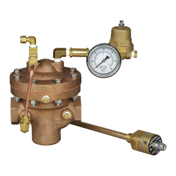
I. DESCRIPTION AND SCOPE
The Model PTR-1 uses the pressure set point of a back pressure regulator (Unloader) to control the outlet
pressure of the reducing regulator. In addition a temperature probe is used to protect downstream piping systems
and equipment from experiencing temperature excursions below the desired minimum operating temperature
due to equipment malfunction or overdraw of system capacity. This model is suitable for gaseous applications.
II. REFERENCES
Refer to Technical Bulletin PTR-1-TB for tech ni cal
specifications.
III. INSTALLATION
For welded installations, all internal trim parts, seals
and diaphragm(s) must be removed from reg u la tor
body prior to welding into pipeline. The heat of fusion
welding will dam age non-metallic parts if not re moved.
1. This regulator may be rotated around pipe axis
360 degrees. For ease of maintenance, the
rec om mend ed position is with the cover dome
(25) up wards.
2. Provide space below, above, and around reg u la-
tor for removal of parts during maintenance.
3. Install block valves and pressure gauges to pro-
vide means for adjustment, operation, bypass,
or removal of the regulator. A pipeline strainer
is recommended before inlet to remove typical
pipe line debris from entering valve and damaging
internal "soft goods", primarily the dynamic seal.
4. Downstream Sensing Installation Considerations
– Internal or External Sensing:
a. The regulator may be installed with inter-
nal or external sensing. Unless otherwise
spec i fied, the regulator is supplied by factory
INSTALLATION, OPERATION & MAINTENANCE MANUAL (IOM)
MODEL PTR-1
D
IRECT-ACTING, PRESSURE LOADED,
PRESSURE REDUCING REGULATOR
with BACK PRESSURE UNLOADER
and LOW TEMPERATURE PROBE
CAUTION
SECTION I
SECTION II
CW
CCW –
SECTION III
Installation of adequate overpressure pro tec tion is
recommended to pro tect the reg u la tor from overpressure
and all down stream equip ment from damage in the event
of regulator failure.
with internal sensing. The regulator may be
con vert ed in the field to external sensing. (See
Section VII Maintenance, Part G – Converting
Internal/External Sensing.
b. Reference PTR-1-TB, Table -11 for rec om-
men da tions when to apply external sensing.
c. For internal sensing, no external line is re-
quired. For external sensing, use an external
control line. The line is connected from the
1/4" (DN8) NPT tap (Port 5 – See Fig. 5) on
the side of the body di a phragm flange to a
pressure tap down stream of the regulator. Use
1/4" or 3/8" (DN8 or 10) outer di am e ter tubing
or 3/8" (DN10) pipe having an inner di am e ter
equiv a lent to Schedule 40 pipe.
5. Install probe in upstream piping, connect a
sensing line from inlet of probe to the tee on
top of the loading chamber of the main regula-
tor. See Section VII. M.
ABBREVIATIONS
–
Clockwise
Counter Clockwise
ITA
–
Inner Trim Assembly
CAUTION
IOM-PTR-1
01-17
Advertisement

Related Manuals for cashco PTR-1


Summary of Contents for cashco PTR-1
- Page 1 SECTION I I. DESCRIPTION AND SCOPE The Model PTR-1 uses the pressure set point of a back pressure regulator (Unloader) to control the outlet pressure of the reducing regulator. In addition a temperature probe is used to protect downstream piping systems and equipment from experiencing temperature excursions below the desired minimum operating temperature due to equipment malfunction or overdraw of system capacity.
-
Page 2: Principle Of Operation
Unloader & PI Low Temp. on the nameplate that the Inlet and Outlet pres sure and Probe temperature ratings are at different levels. Model PTR-1 - External Sense Recommended Piping Schematic For Pressure Reducing Regulator With Low Temperature Probe SECTION IV IV. -
Page 3: Maintenance
Step 9 for a Model PTR-1. The max i mum rise in outlet pres sure on 9. Develop system flow to a level near its expected de creas ing flow should not exceed the 10%. - Page 4 (14.1). Examine diaphragm to determine nuts (12) uniformly. whether failed; determine if op er at ing condi- tions are ex ceed ing pressure, pressure drop 6. Place matchmarks on body (23) and cover or temperature limits. dome (25) flanges. Remove cover dome (25). IOM-PTR-1...
- Page 5 4. Examine the com po nents (27.1, 27.2, 27.3, wiper seal (16). 27.4) of the dy nam ic side seal (27) mechanism c. Lower guide bushing (24) (non-re place- to de ter mine if sig nif i cant leakage was oc cur- able): IOM-PTR-1...
- Page 6 (19) until the 1. Stretch o-ring seal (27.4) over lower cap seal (27.1) edge touches the upper lip of the cage (19). While gently applying force to press the guide bushing (13) into the cage (19), IOM-PTR-1...
- Page 7 (8) and the lower diaphragm groove “ridge” on lower side. g. Place lubricant on valve plug (20) thread ed plate (10), over the upper end of valve plug (20) and temporarily secure with diaphragm end. Engage diaphragm lock nut (7) with IOM-PTR-1...
- Page 8 F – Main Regulator Reassembly. H. Pressure Testing: 1. If a hydrostatic pressure test is performed, pressure must be applied to all three of cover Figure 5: Location of Auxiliary Ports dome (25), inlet and outlet of body at the same level. IOM-PTR-1...
- Page 9 5. Remove the diaphragm subassembly con- grease into de pres sion of spring button (5) sist ing of the pressure plate nut (7), lock where ad just ing screw (3) bears. Set spring wash er (8), pressure plate (10), diaphragm IOM-PTR-1...
- Page 10 “oxygen clean”, Option -55, main te nance must include a lev el of clean li- ness equal to Cashco's clean ing stan dard #S-1134. Contact factory for de tails. 4. Inspect the surface in the body (1) cavity where seat ring (15) rests.
-
Page 11: Section Viii
SECTION VIII VIII. PRESSURE LOADING 2. The Model PTR-1 exhibits a deviation in outlet 1. The Loading pressure for the PTR-1 is supplied controlled pressure when the inlet pressure var- from the inlet (P1) and is regulated with by the ies;... -
Page 12: Troubleshooting Guide
Remedies Differential pressure across diaphragm may A1. Be aware of limits as well as where the various pressures are acting. have exceeded limits. (See Table 6 in PTR-1- Install pressure safety equipment as necessary. Leakage at diaphragm flange. Possible Causes Remedies Body bolts not torqued properly. - Page 13 (last digit is alpha character that reflects revision level for the product). PARTS "KIT" for FIELD REPAIR: – – Contact your local Cashco, Inc., Sales Rep re sen- ta tive with the Serial Number and Product code. NEW REPLACEMENT UNIT: Identify the parts and the quantity required to repair the unit from the "BOM"...
- Page 14 Cashco, Inc. does not assume responsibility for the selection, use or maintenance of any product. Responsibility for proper selection, use and maintenance of any Cashco, Inc. product remains solely with the purchaser.
- Page 15 Adjusting Screw Lock Nut Spring Button Range Spring Pressure Plate Nut Lock Washer Travel Stop Pressure Plate 11 * Diaphragm 12 * Diaphragm Gasket 13 * Plug Gasket 14 * Plug 15 * Seat Ring * Recommended Repair Parts. IOM-PTR-1...
- Page 16 ATEX requires that all components and equipment be evaluated. Cashco pressure regulators are considered components. Based on the ATEX Directive, Cashco considers the location where the pressure regulators are installed to be classified Equipment-group II, Category 3 because flammable gases would only be present for a short period of time in the event of a leak.
- Page 17 If the above issues are addressed by selecting options that do not have potential sources of ignition, avoiding options that have not been assessed, and by taking the proper usage issue precautions, then Cashco regulators can be considered to be a mechanical device that does not have its own source of ignition and thus falls outside the scope of the ATEX directive.
Need help?
Do you have a question about the PTR-1 and is the answer not in the manual?
Questions and answers