MDS iNET 900 Installation Manual
Wireless ip/ethernet transceiver
Hide thumbs
Also See for iNET 900:
- User manual (130 pages) ,
- Installation manual (20 pages) ,
- User manual (190 pages)

Related Manuals for MDS iNET 900


Summary of Contents for MDS iNET 900
- Page 1 NET 900 ™ Wireless IP/Ethernet Transceiver MDS 05-2873A01, Rev. A FEBRUARY 2002...
-
Page 2: Table Of Contents
TECHNICAL ASSISTANCE ..........19 FACTORY SERVICE .............19 INSTALLATION REFERENCE CHART ..... (Center Insert) Copyright Notice This publication is protected by U.S.A. copyright law. Copyright 2002, Microwave Data Systems Inc. All rights reserved. MDS 05-2873A01, Rev. A MDS iNET 900 Installation Guide... - Page 3 MDS iNET 900 MDS i NET 900 Installation Guide MDS 05-2873A01, Rev. A...
-
Page 4: Operational & Safety Notices
STD C22.2 No. 213-M1987. FM/UL/CSA Conditions of Approval The MDS iNET 900 is not acceptable as a stand-alone unit for use in the hazardous locations described above. It must either be mounted within another piece of equip- ment, which is certified for hazardous locations, or installed within guidelines, or con- ditions of approval, as set forth by the approving agencies. - Page 5 FCC. At no time shall the product be used as a board-only solution. Further, if the MDS module is installed inside another device, such that its FCC ID number is not visible, a label must be affixed to the exterior of the device stating: “Contains FCC ID: E5M-INET900”...
-
Page 6: Product Description
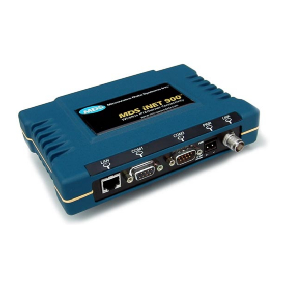
PRODUCT DESCRIPTION The MDS i NET 900 is a device designed to provide wireless local area network (LAN) services with plug-and-play hardware. The unit can be reconfigured for any one of three operating arrange- ments; some require the use of Authorization Keys (alphanumeric code) purchased from MDS. -
Page 7: Installation Planning
A typical i NET 900 product shipment consists of an i NET 900 unit, a power connector and an installation guide. Below are the basic steps for installing an MDS i NET 900 unit. Should further information be required, see “TECHNICAL ASSISTANCE”... -
Page 8: Step 2-Install The Antenna
The power supply used with the iNET 900 should be equipped with overload protection (NEC Class 2 rating), to protect against a short circuit between its output terminals and the iNET 900 power connector. It typically takes about 30 seconds for the iNET 900 to power NOTE: up and be ready for operation. -
Page 9: Step 4-Review The Radio's Configuration
Step 4—Review the iNET 900’s Configuration Two essential settings for the iNET 900 unit should be known before placing the unit into service. They are: • Device Mode—Access Point, or Remote. (Default) • Network Name—Common identifier used by all of the iNET 900 units, which are part of the same network. -
Page 10: Step 5-Connect The Data Equipment
Program the iNET 900 Network Name. e. Review other settings and make changes if necessary, such as the unit password and IP address. Repeat the above steps for each iNET 900 in the network. The Management System’s “configuration files” will aid in NOTE: uniformly configuring multiple iNET 900 units. -
Page 11: Step 6-Check For Normal Operation
• When the iNET 900 network seems to be operating properly based on observation of the unit’s LEDs, connect a computer to the iNET 900’s data port that will be used by the local terminal equip- ment. Use the command to verify the communications link PING integrity with the Access Point unit. -
Page 12: Performance Optimization
Performance Optimization After the basic operation of the iNET 900 network has been estab- lished, you may wish to optimize its performance using some of the suggestions given here. The effectiveness of these techniques will vary with the amount of data being handled. - Page 13 The path to the Management System menu item is shown in bold text below each step of the procedure. Procedure 1. Verify the iNET 900 Remote is associated with an Access Point unit. Observe the condition of the LINK LED. LINK LED = On or Blinking This will indicate that you have an adequate signal level for the measurements and it is safe to proceed.
- Page 14 1. Place the Access Point unit into the Radio Test Mode. Main Menu>Diagnostic Tools>Radio Test>Test Mode>Y>ON Use the same test frequency at the iNET 900 Access Point and Remote units. You may use any frequency within the 902–928 MHz band. Default = 915.0000 MHz Turn on the Access Point transmitter.
-
Page 15: Troubleshooting
• Adequate and stable primary power • An efficient and properly aligned antenna system • Secure connections (RF, data & power) • Proper programming of the iNET 900’s operating parameters, especially Device Mode selection (Access Point/Remote), Net- work Name, and IP Address •... - Page 16 Use the PING command to test communication with iNET 900 units in the local radio system. d. If successful with local PING, attempt to PING an IP unit attached to an iNE 900T unit.
-
Page 17: Fuse Replacement Procedure
FUSE REPLACEMENT PROCEDURE An internal fuse protects the iNET 900 unit. The fuse will be blown by a reverse polarity of the primary DC power, an over-voltage transient or an internal failure. The fuse should not be replaced until you are cer- tain you are in a safe environment. -
Page 18: Mds I Net Specifications
Increments of 1.0 dB, set by user Duty Cycle: Continuous Output Impedance: 50 Ohms RECEIVER: Type: Double conversion superheterodyne –92 dBm @ 512 kbps < 1x10 - Sensitivity: –100 dBm @ 256 kbps < 1x10 - MDS 05-2873A01, Rev. A MDS iNET 900 Installation Guide... - Page 19 MDS iNET 900 MDS iNET 900 Installation Guide MDS 05-2873A01, Rev. A...
-
Page 20: Technical Assistance
Microwave Data Systems’ Web site at www.microwavedata.com. FACTORY SERVICE If return of the equipment is necessary, please contact the MDS Cus- tomer Support Team. You will be issued a Returned Material Autho- rization (RMA) number. The RMA number will help expedite the repair so that the equipment can be repaired and returned to you as quickly as possible. - Page 21 MDS iNET 900 MDS iNET 900 Installation Guide MDS 05-2873A01, Rev. A...
- Page 22 175 Science Parkway, Rochester, New York 14620 General Business: +1 (585) 242-9600 FAX: +1 (585) 242-9620 Web: www.microwavedata.com...
-
Page 23: Installation Reference Chart
BASIC CONFIGURATION DEFAULTS The iNET 900's Management System can be accessed through the COM1 Port using a terminal emulator. The basic items listed below, and many other parameters and tools can be accessed through this tool. HTTP and Telnet access, and changing some parameters are controlled by password. - Page 24 LED FUNCTIONS & INDICATIONS LAN ..ON ....LAN detected PWR ..ON ....Primary power (DC) present Blinking ..Data TX/RX Blinking ..Slowly = Sleep mode OFF ..LAN not detected Quickly = Alarm present OFF ..Primary power (DC) absent COM1 ...Blinking ..Data TX/RX Activity Access Point OFF ..No data activity LINK ..ON ....Default state...
Need help?
Do you have a question about the iNET 900 and is the answer not in the manual?
Questions and answers