Table of Contents
Advertisement
Quick Links
Advertisement
Table of Contents

Subscribe to Our Youtube Channel
Related Manuals for MDS 4710A


Summary of Contents for MDS 4710A
- Page 1 MDS 4710A/9710A Data Transceiver MDS 05-3305A01, REV. A JANUARY 1999...
- Page 2 QUICK START GUIDE Below are the basic steps for installing the transceiver. Detailed instructions are given in ÒINSTALLA- TIONÓ on page 9 of this guide. Install and connect the antenna system to the radio ¥ Use good quality, low loss coaxial cable. Keep the feedline as short as possible. ¥...
-
Page 3: Table Of Contents
6.0 TROUBLESHOOTING ............... 31 6.1 LED Indicators ................32 6.2 Event Codes ...................32 7.0 TECHNICAL REFERENCE ............34 7.1 MDS 4710A/9710A Transceiver SpeciÞcations ......34 7.2 Helical Filter Adjustment ..............36 7.3 Performing Network-Wide Remote Diagnostics ......37 7.4 Upgrading the RadioÕs Software .............39 7.5 dBm-Watts-Volts Conversion Chart ..........40... - Page 4 This product is available for use in Class I, Division 2, Groups A, B, C & D Hazardous Locations. Such locations are defined in Article 500 of the National Fire Protection Association (NFPA) publication NFPA 70, otherwise known as the National Electrical Code. MDS 4710/9710 Installation and Operation Guide MDS 05-3305A01, Rev. A.1...
- Page 5 Refer to Articles 500 through 502 of the National Electrical Code (NFPA 70) for further information on hazardous locations and approved Division 2 wiring methods. MDS 05-3305A01, Rev. A Installation and Operation Guide...
- Page 6 Customer Service Team using the information at the back of this guide. In addition, manual updates can often be found on the MDS Web site at www.microwavedata.com.
-
Page 7: General
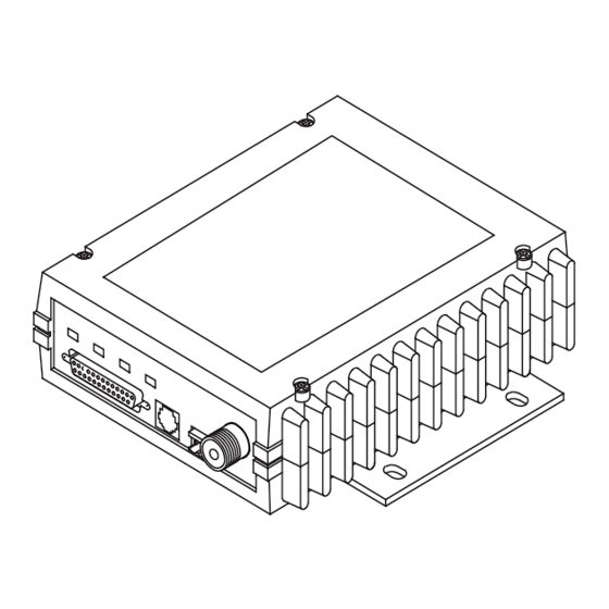
1.0 GENERAL 1.1 Introduction This guide presents installation and operating instructions for the MDS 4710A/9710A (400/900 MHz) digital radio transceivers. These transceivers (Figure 1) are data telemetry radios designed to operate in a point-to-multipoint environment, such as electric utility Supervisory Control and Data Acquisition (SCADA) and distribution automation, lottery systems, gas field automation, water and wastewater SCADA, and on-line transaction processing applications. -
Page 8: Applications
Since the cost of leasing a dedicated-pair phone line is quite high, a desirable alternative may be replacing the phone line with a radio path. MDS 4710A/9710A Installation and Operation Guide MDS 05-3305A01, Rev. A... - Page 9 Different frequencies must be used for transmit and receive. This is the method used in many MAS systems, and is shown in Figure 2. This is useful for high-speed polling applica- tions. MDS 05-3305A01, Rev. A MDS 4710A/9710A Installation and Operation Guide...
-
Page 10: Model Number Codes
NOTE: 4710A/9710A remotes do not support full-duplex operation. Switched Carrier operation is a half-duplex mode of operation where the master station transmitter is keyed to send data and unkeyed to receive. Single Frequency (Simplex) Operation Single frequency operation (also known as simplex) is a special case of switched carrier operation. -
Page 11: Accessories
Figure 5. 9710A Model Number Codes 1.4 Accessories The transceiver can be used with one or more of the accessories listed in Table 1. Contact Microwave Data Systems for ordering information. Table 1. MDS 4710A/9710A Optional Accessories Accessory Description MDS P/N Hand-Held Terminal... -
Page 12: Glossary Of Terms
DCE ÑData Circuit-terminating Equipment (or Data Communications Equipment). In data communications terminology, this is the ÒmodemÓ side of a computer-to-modem connection. The MDS 4710A/9710A is a DCE device. Digital Signal Processing ÑSee DSP . MDS 4710A/9710A Installation and Operation Guide... - Page 13 DSP ÑDigital Signal Processing. In the MDS 4710A/9710A trans- ceiver, the DSP circuitry is responsible for the most critical real-time tasks; primarily modulation, demodulation, and servicing of the data port. DTE ÑData Terminal Equipment. A device that provides data in the form of digital signals at its output.
- Page 14 Multiple Address SystemÑSee MAS. Network-Wide DiagnosticsÑAn advanced method of controlling and interrogating MDS radios in a radio network. Non-intrusive diagnosticsÑSee Passive messaging. Passive messagingÑThis is a mode of diagnostic gathering that does not interrupt SCADA system polling communications. Diagnostic data is collected non-intrusively over a period of time;...
-
Page 15: Installation
1. Mount the transceiver to a stable surface using the brackets supplied with the radio. 2. Install the antenna and antenna feedline for the station. Preset direc- tional antennas in the desired direction. MDS 05-3305A01, Rev. A MDS 4710A/9710A Installation and Operation Guide... - Page 16 Set the operating frequencies using the (transmit) and TX xxx.xxxx (receive) commands. RX xxx.xxxx Press after each command. After programming, the HHT ENTER reads to indicate successful entry. PROGRAMMED OK MDS 4710A/9710A Installation and Operation Guide MDS 05-3305A01, Rev. A...
-
Page 17: Transceiver Mounting
(Figure 8) or corner reflector antenna is generally recom- mended at remote sites to minimize interference to and from other users. Antennas of this type are available from several manufacturers. MDS 05-3305A01, Rev. A MDS 4710A/9710A Installation and Operation Guide... - Page 18 0.64 dB 1.28 dB 6.40 dB 7/8 inch HELIAX 1-1/4 inch HELIAX 0.10 dB 0.48 dB 0.95 dB 4.75 dB 1-5/8 inch HELIAX 0.08 dB 0.40 dB 0.80 dB 4.00 dB MDS 4710A/9710A Installation and Operation Guide MDS 05-3305A01, Rev. A...
-
Page 19: Power Connection
The following example describes Sleep Mode implementation in a typ- ical system. Using this information, you should be able to configure a system that will meet your own particular needs. MDS 05-3305A01, Rev. A MDS 4710A/9710A Installation and Operation Guide... - Page 20 Do not connectÑReserved for future use. PTTÑPush to Talk. This line is used to key the radio with an active-high signal of +5 Vdc. MDS 4710A/9710A Installation and Operation Guide MDS 05-3305A01, Rev. A...
-
Page 21: Operation
2. Observe the LED status panel for the proper indications (Table 3. If not done earlier, reÞne the antenna heading of the station to maxi- mize the received signal strength (RSSI) from the master station. MDS 05-3305A01, Rev. A MDS 4710A/9710A Installation and Operation Guide... -
Page 22: Led Indicators
INTERFACE received signal level and the DC voltage on Pin 21 of the DATA INTER- connector. (Note: Readings are not accurate for incoming signal FACE strengths above Ð50 dBm.) MDS 4710A/9710A Installation and Operation Guide MDS 05-3305A01, Rev. A... -
Page 23: Transceiver Programming
Contact MDS for ordering information. 5.1 Hand-Held Terminal Connection & Startup This section gives basic information for connecting and using the MDS Hand-Held Terminal. For more information about the terminal, refer also to the instructions included with each HHT kit. -
Page 24: Hand-Held Terminal Setup
1. Plug the HHT into the connector. Enable the setup mode by DIAG. pressing the keys in sequence. The display SHIFT CTRL SPACE shown in Figure 11 appears. MDS 4710A/9710A Installation and Operation Guide MDS 05-3305A01, Rev. A... -
Page 25: Keyboard Commands
To enter a command, type the command, followed by an key- ENTER stroke. For programming commands, the command is followed by and the appropriate information or values, then SPACE ENTER MDS 05-3305A01, Rev. A MDS 4710A/9710A Installation and Operation Guide... - Page 26 ÑThe command is unavailable to the user. Refer to the ACCESS DENIED command descriptions for command information. Ñ The command was unable to write to EEPROM. EEPROM FAILURE INIT This is a serious internal radio error. Contact MDS. MDS 4710A/9710A Installation and Operation Guide MDS 05-3305A01, Rev. A...
- Page 27 Details page Set or display the ownerÕs message. OWN [XXX...] Details page Set or display the ownerÕs name. PTT [0Ð255] Details page Set or display the Push-to-Talk delay in milliseconds. MDS 05-3305A01, Rev. A MDS 4710A/9710A Installation and Operation Guide...
-
Page 28: Detailed Command Descriptions
Secondly, you can set or change the existing data by typing the command, followed by a space, and then the desired entry. In the list below, allowable programming variables, if any, are shown in brackets following the command name. MDS 4710A/9710A Installation and Operation Guide MDS 05-3305A01, Rev. A... - Page 29 Unit address not programmed Data parity error Data framing error Configuration error 6V regulator output not in valid range DC input power is not in valid range Internal Temperature not in valid range MDS 05-3305A01, Rev. A MDS 4710A/9710A Installation and Operation Guide...
- Page 30 (stores) the data until enough bytes have arrived to cover worst-case gaps in transmission. This mode of operation is required for protocols such as MODBUSª that do not allow gaps in their data transmission. MDS 4710A/9710A Installation and Operation Guide MDS 05-3305A01, Rev. A...
- Page 31 , keying can be stimulated by the input of characters at the data port. Hardware flow control is implemented by signaling the CTS line if data arrives faster than it can be buffered and transmitted. MDS 05-3305A01, Rev. A MDS 4710A/9710A Installation and Operation Guide...
- Page 32 The HHT display is too small to list all the command settings at one time. Therefore, this command is most useful if the command is issued from a computer or full-screen terminal. HREV This command displays the transceiverÕs hardware revision level. MDS 4710A/9710A Installation and Operation Guide MDS 05-3305A01, Rev. A...
- Page 33 (trigger on major alarms) AMASK FFFF 0000 (20 minute time-out timer) RXTOT This command activates the transmitter. See also the command. DKEY MODEL This command displays the radioÕs model number code. MDS 05-3305A01, Rev. A MDS 4710A/9710A Installation and Operation Guide...
- Page 34 This command continuously displays the radioÕs Received Signal Strength Indication (RSSI) in dBm units, until you press the Enter key. Incoming signal strengths from Ð50 dBm to Ð120 dBm can be read. MDS 4710A/9710A Installation and Operation Guide MDS 05-3305A01, Rev. A...
- Page 35 RTU [ON/OFF/0-80] This command re-enables or disables the radioÕs internal RTU simu- lator, which runs with MDSÕ proprietary polling programs (poll.exe and rsim.exe). The internal RTU simulator is available whenever a radio has diagnostics enabled. This command also sets the RTU address that the radio will respond to.
- Page 36 ENTER key. Detailed descriptions of event codes are provided in Table 9 on page TEMP This command displays the internal temperature of the transceiver in degrees Celsius. MDS 4710A/9710A Installation and Operation Guide MDS 05-3305A01, Rev. A...
-
Page 37: Troubleshooting
¥ Proper programming of the transceiverÕs operating parameters (see Section 5.0, TRANSCEIVER PROGRAMMING page 17). ¥ The correct interface between the transceiver and the connected data equipment (correct cable wiring, proper data format, timing, etc.) MDS 05-3305A01, Rev. A MDS 4710A/9710A Installation and Operation Guide... -
Page 38: Led Indicators
(or seriously hamper) further operation of the transceiver. Major alarms generally indicate the need for factory repair. Contact MDS for further assistance. Minor AlarmsÑreport conditions that, under most circumstances will not prevent transceiver operation. This includes out-of-tolerance condi- tions, baud rate mismatches, etc. - Page 39 27, 28 Not used Minor The transceiverÕs internal temperature is approaching an out-of-tolerance condition. If the temperature drifts outside of the recommended operating range, system operation may fail. MDS 05-3305A01, Rev. A MDS 4710A/9710A Installation and Operation Guide...
-
Page 40: Technical Reference
1. Normal refers to:Temperature, +15 to +35 degrees C Humidity, 20% to 75% Voltages, Nominal Specified 2. Extreme refers to:Temperature, Ð25 to +55 degrees C Humidity, 20% to 75% Voltages, ±10% MDS 4710A/9710A Installation and Operation Guide MDS 05-3305A01, Rev. A... - Page 41 Maximum Usable Sensitivity: Ð113 dBm BER at 10 (normal Ð2 Ð107dBm BER at 10 (extreme 1. Normal refers to:Temperature, +15 to +35 degrees C Humidity, 20% to 75% Voltages, Nominal Specified MDS 05-3305A01, Rev. A MDS 4710A/9710A Installation and Operation Guide...
-
Page 42: Helical Filter Adjustment
RJ-11 (may use DB-25 instead if Pin 23 is grounded to enable diagnostics channel) I/O Devices: MDS Hand Held Terminal or PC with MDS software 7.2 Helical Filter Adjustment If the frequency of the radio is changed more than 5 MHz, the helical filters should be adjusted for maximum received signal strength (RSSI). -
Page 43: Performing Network-Wide Remote Diagnostics
Figure 13. Helical Filter Locations 7.3 Performing Network-Wide Remote Diagnostics Diagnostics data from a remote radio can be obtained by connecting a laptop or personal computer running MDS InSite diagnostics software to any radio in the network. Figure 14 shows an example of a setup for performing network-wide remote diagnostics. - Page 44 DTYPE ROOT radio. A complete explanation of remote diagnostics can be found in MDSÕ Network-Wide Diagnostics System Handbook. See the Handbook for more information about the basic diagnostic procedures outlined below. 1. Program one radio in the network as the root radio by entering the command at the radio.
-
Page 45: Upgrading The Radioõs Software
5. Connect same-site radios using a null-modem cable at the radiosÕ diagnostic ports. 6. Connect a PC on which MDS InSite software is installed to the root radio, or to one of the nodes, at the radioÕs diagnostic port. (This PC... -
Page 46: Dbm-Watts-Volts Conversion Chart
10.0 -136 10mW -137 2.25 .1µW -138 6.4mW .001nW -139 .500 -140 .01ÄW .445 5.75 .400 3.2mW .355 2.5mW 1.25 .320 2.0mW 1.18 .280 1.6mW 1.00 3.51 .252 1.25mW 0.90 MDS 4710A/9710A Installation and Operation Guide MDS 05-3305A01, Rev. A... -
Page 47: Index
See Decibel ASENSE (set alarm output state) dBi, deÞned BAUD (set/display rate, encoding) dBm, deÞned BUFF (set/display data handling mode) CKEY (enable/disable continuous keying) CTS (set/display CTS line response timer) pinout (Pin 8) MDS 05-3324A01, Rev. A Installation and Operation Guide... - Page 48 EEPROM FAILURE error message Enable/disable continuous keying (CKEY command) diagnostic channel, pinout (Pin 23) Illustrations internal RTU (RTU command) 4710A model number codes network-wide diagnostics (DLINK command) 9710A model number codes network-wide diagnostics, procedures antenna, Yagi Environment speciÞcations Hand-Held Terminal (HHT) connected to transceiver MDS 05-3324A01, Rev.
- Page 49 Pinouts on data interface PLC (Programmable Logic Controller), deÞned TXD, Pin 2 Point-to-multipoint Loss. See Signal deÞned system Point-to-point link, illustrated MAS (Multiple Address System) system deÞned illustration Poll, deÞned MDS 05-3324A01, Rev. A Installation and Operation Guide...
- Page 50 PC Station, illustrated display revision level Resetting upgrades (.S28 Þles) Hand-Held Terminal (HHT) (SHIFT,CTRL,SPACE keys) upgrading remote RTU reset (Pin 15) transceiver (INIT command) used for diagnostics and programming MDS 05-3324A01, Rev. A Installation and Operation Guide...
- Page 51 Transmit Audio Input pinout (Pin 9) Transmitter speciÞcations system speciÞcations 31Ð33 Troubleshooting connecting Hand-Held Terminal (HHT) for displaying alarm codes performing network-wide diagnostics STAT command (Status) using PC software for TX command TXD LED description Pin 2 MDS 05-3324A01, Rev. A Installation and Operation Guide...
- Page 52 NOTES...
- Page 53 NOTES...
- Page 54 NOTES...
-
Page 55: In Case Of Difficulty
IN CASE OF DIFFICULTY... MDS products are designed for long life and trouble-free operation. However, this equipment, as with all electronic equipment, may have an occasional component failure. The following informa- tion will assist you in the event that servicing becomes necessary. - Page 56 175 Science Parkway, Rochester, New York 14620 General Business: +1 (716) 242-9600 FAX: +1 (716) 242-9620 World Wide Web: http://www.mdsroc.com...
Need help?
Do you have a question about the 4710A and is the answer not in the manual?
Questions and answers