Table of Contents
Advertisement
Advertisement
Table of Contents

Related Manuals for MDS MDS 4710B


Summary of Contents for MDS MDS 4710B
- Page 1 MDS 4710B/9710B Data Transceiver MDS 05-3316A01, REV. E SEPTEMBER 2000...
- Page 2 QUICK START GUIDE Below are the basic steps for installing the transceiver. Detailed instructions are given in “INSTALLA- TION” on page 5 of this guide. Install and connect the antenna system to the radio • Use good quality, low loss coaxial cable. Keep the feedline as short as possible. •...
-
Page 3: Table Of Contents
5.2 Command Summary ..............19 5.3 Command Equivalents for Older Transceivers ....... 21 5.4 Detailed Command Descriptions ........... 22 BAUD [9600 abc] ................22 CTS [0–255] ................. 23 DECF [0–100] ................23 MDS 05-3316A01, Rev. E MDS 4710B/9710B I/O Guide... - Page 4 TXLEVEL [–20...+3, AUTO] ............31 6.0 TROUBLESHOOTING ............... 31 6.1 LED Status Indicators ..............32 6.2 Event Codes ................... 32 Checking for Alarms—STAT command......... 32 Major Alarms vs. Minor Alarms............. 33 Event Code Definitions ..............33 MDS 4710B/9710B I/O Guide MDS 05-3316A01, Rev. E...
-
Page 5: Copyright Notice
• Services and support we provide to our internal and external customers. Total Customer Satisfaction Achieved Through: • Processes that are well documented and minimize variations. • Partnering with suppliers who are committed to providing quality and service. MDS 05-3316A01, Rev. E MDS 4710B/9710B I/O Guide... - Page 6 5. When installed in a Class I, Div. 2, Groups A, B, C or D hazardous location, observe the following: Do not disconnect WARNING —EXPLOSION HAZARD— equipment unless power has been switched off or the area is known to be non-hazardous. MDS 4710B/9710B I/O Guide MDS 05-3316A01, Rev. E...
- Page 7 Customer Service Team using the information at the back of this guide. In addition, manual updates can often be found on the MDS web site at www.microwavedata.com.
- Page 8 MDS 4710B/9710B I/O Guide MDS 05-3316A01, Rev. E...
-
Page 9: General
This guide presents installation and operating instructions for the MDS 9710B (900 MHz) and MDS 4710B (400 MHz) radio transceiver. For brevity, the model number “MDS x710B” is used in this guide to repre- sent both models, except where it is necessary to distinguish between the two. -
Page 10: Point-To-Point System
HOST COMPUTER SWC ON SWC ON Figure 3. Typical point-to-point link Continuously Keyed versus Switched Carrier Operation The keying behavior of the master station can be used to describe an MAS system. MDS 4710B/9710B I/O Guide MDS 05-3316A01, Rev. E... -
Page 11: Single Frequency (Simplex) Operation
, for communica- SWC OFF tions with a continuously keyed master. MDS x710B radios always transmit using switched carrier operation. If a radio system is configured with an x710B as the master, all radios (master and remotes) must be configured with . -
Page 12: Accessories
Figure 4. Model number codes 1.3 Accessories The transceiver can be used with one or more of the accessories listed in Table 1. Contact Microwave Data Systems for ordering information. Table 1. MDS x710B optional accessories Accessory Description MDS P/N... -
Page 13: Installation
Table 1. MDS x710B optional accessories (Continued) Accessory Description MDS P/N RJ-11 to DB-9 adapter Used to connect a PC to the radio’s 03-3246A01 DIAGNOSTICS port RS-232 to RS-422 External adapter plug that converts the 03-2358A01 Converter Assembly radio’s DATA INTERFACE connector to RS-422 compatible signaling. -
Page 14: Installation Steps
“>” prompt. b. Set the operating frequencies using the (transmit) TX xxx.xxxxx (receive) commands. Press . After pro- RX xxx.xxxxx ENTER gramming, the HHT reads to indicate success- PROGRAMMED OK ful entry. MDS 4710B/9710B I/O Guide MDS 05-3316A01, Rev. E... -
Page 15: Using The Radio's Sleep Mode
Connect this line to Pin 12 of the radio’s connector. This will allow each RTU to DATA INTERFACE be polled once per hour with a significant savings in power con- sumption. MDS 05-3316A01, Rev. E MDS 4710B/9710B I/O Guide... -
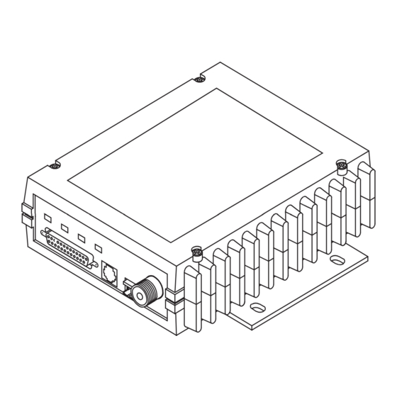
Page 16: Transceiver Mounting
2.5 amperes of continuous current. The red wire on the power cable is the positive lead; the black is nega- tive. NOTE: The radio is designed for use only in negative ground systems. MDS 4710B/9710B I/O Guide MDS 05-3316A01, Rev. E... -
Page 17: Antennas And Feedlines
0.08 dB 0.42 dB 0.83 dB 4.15 dB 1 1/4 inch HELIAX 0.06 dB 0.31 dB 0.62 dB 3.10 dB 1 5/8 inch HELIAX 0.05 dB 0.26 dB 0.52 dB 2.60 dB MDS 05-3316A01, Rev. E MDS 4710B/9710B I/O Guide... -
Page 18: Data Interface Connections
Table 4.) The data interface speed may differ from the data rate used over the air. If synchronous data transmission is required, an external synchro- nous-to-asynchronous converter is required. Contact MDS for addi- tional information. Table 4. Modem type versus speed... - Page 19 Do not connect—Reserved for future use. PTT—Push to Talk. This line is used to key the radio with an active-high signal of +5 Vdc. MDS 05-3316A01, Rev. E MDS 4710B/9710B I/O Guide...
-
Page 20: Operation
Pin Description Remote RTU Reset. This line can be used to reset an RTU from a command issued remotely with MDS InSite software. See “Remote RTU Reset” on page 14 for additional information. This pin can be toggled remotely, using InSite software or locally using the radio configuration software. -
Page 21: Reading Led Status Indicators
• Continuous—Radio is receiving a data signal from a continuously keyed radio. An RS-232 mark signal is being received at the DATA INTERFACE. An RS-232 mark signal is being sent out from the DATA INTERFACE. MDS 05-3316A01, Rev. E MDS 4710B/9710B I/O Guide... -
Page 22: Rssi Chart
Invisible place holder SIGNAL LEVEL (dBm) Figure 9. RSSI versus DC voltage (typical) 3.4 Remote RTU Reset Using MDS InSite software (version 4.1 or later), a command can be issued remotely to toggle Pin 15 of the connector. DATA INTERFACE From InSite: 1. -
Page 23: Remote Maintenance And Diagnostics Levels
The three DIAGLEV levels of diagnostics are compatible with the corresponding diagnostics levels available in the MDS 2300 and 4300 series transceivers. The diagnostics levels are as follows: • Mode 1—Loopback • Mode 2—Advanced Diagnostics •... -
Page 24: Hand-Held Terminal Connection & Start-Up
4.1 Hand-Held Terminal Connection & Start-up This section gives basic information for connecting and using the MDS Hand-Held Terminal. For more information about the terminal, refer also to the instructions included with each HHT kit. The steps below assume that the HHT has been configured for use with the MDS x710B Transceiver (80 character screen display). -
Page 25: Hand-Held Terminal Setup
Scroll On 33rd Baud Rate 1200 Cursor Comm bits 8,1,n CRLF for CR Parity Error Self Test FAST Key Repeat Key Beep Echo Screen Size Shift Keys Menu Mode LONG Ctl Chars PROCS MDS 05-3316A01, Rev. E MDS 4710B/9710B I/O Guide... -
Page 26: Transceiver Commands
—The requested action could not be completed. There COMMAND FAILED may be a problem with the software; contact MDS. —The software was unable to program the EEPROM, NOT PROGRAMMED or the requested display item was not programmed. This is a serious internal radio error;... -
Page 27: Command Summary
This is a serious internal error; contact MDS. 5.2 Command Summary Table 8 is a command list applicable to the MDS x710 radios. Table 9 is a list of the Local Maintenance commands that can be used to adjust items such as operating frequency. These tables are summaries only. - Page 28 Set or display the Time-out Timer delay in Details page 31 seconds. TX [xxx.xxxxx] Details Set or display the transmit frequency. page 31 TXLEVEL [–20...+3, Set or display the analog audio transmit level in AUTO] Details page 31 dBm. MDS 4710B/9710B I/O Guide MDS 05-3316A01, Rev. E...
-
Page 29: Command Equivalents For Older Transceivers
5.3 Command Equivalents for Older Transceivers There are several programming commands used with earlier trans- ceivers that also function with the MDS x710B. Table 10 lists these commands along with cross references to their equivalents in the MDS x710B command set. In these instances, either the new or old command may be used. -
Page 30: Detailed Command Descriptions
Invisible place holder Table 10. Command equivalents for older transceivers Older Transceiver MDS 4710B & 9710B Command Equivalent Command PCTS See CTS [0–255] Details page 23 PPTT See PTT [0–255] Details page 27 PSCD See SCD [0-255] Details page 29 See RX [xxx.xxxxx] Details page 28... -
Page 31: Cts [0-255]
• Mode 1 (Standard Diagnostics) is indicated by • Mode 2 (Advanced Diagnostics) is indicated by • Mode 3 (Remote Maintenance) is indicated by to the diagnostics mode currently used in the radio system. DIAGLEV MDS 05-3316A01, Rev. E MDS 4710B/9710B I/O Guide... -
Page 32: Dkey
De-emphasis compensates (at the receiver) for a signal that has had emphasis applied. Emphasis and de-emphasis functions should not be enabled except when compatibility with older MDS analog radios is required. ESTE This command enables the radio’s squelch tail eliminator (STE) circuit... -
Page 33: Hrev
0 • command is set to 30 seconds and set to • command is set to +37 dBm (5 watts) All other commands stay in the previously established setting. MDS 05-3316A01, Rev. E MDS 4710B/9710B I/O Guide... -
Page 34: Key
4800 bps modem modulation compatible 4800B with the MDS 1000µ, MDS 2310, or the MDS 4310 series of radio prod- ucts equipped with a 4800 bps modem. All baud rates up to 4800 are automatically supported as data is received. The... -
Page 35: Owm [Xxx
50% for the following local maintenance settings. • Power • Frequency RMOV This command restores the old values (after the last command) for RMST the following remote maintenance settings. • Power • Frequency MDS 05-3316A01, Rev. E MDS 4710B/9710B I/O Guide... -
Page 36: Rmrd
RTU [ON/OFF/0-80] This command re-enables or disables the radio’s internal RTU simu- lator, which runs with MDS’ proprietary polling programs (poll.exe and rsim.exe). The internal RTU simulator is available whenever a radio has diagnostics enabled. This command also sets the RTU address that the radio will respond to. -
Page 37: Scd [0-255]
If more than one alarm exists, the word appears at the bottom of MORE the screen and additional alarms are viewed by pressing the key. ENTER Detailed descriptions of alarm codes are provided in Table 11 on page 33. MDS 05-3316A01, Rev. E MDS 4710B/9710B I/O Guide... -
Page 38: Ste
2100 or 4100 series master station, it is important to set at least 20 milliseconds for proper system operation. To use an MDS x710 as a master radio, set If the x710B radio is used in a system that has an x710B radio operating... -
Page 39: Tot [1-255 On/Off]
It is best to begin troubleshooting at the master station, as the rest of the system depends on the master for polling commands. If the master station has problems, the operation of the entire network can be compromised. MDS 05-3316A01, Rev. E MDS 4710B/9710B I/O Guide... -
Page 40: Led Status Indicators
Checking for Alarms—STAT command To check for alarms, enter on the HHT. If no alarms exist, the mes- STAT sage appears at the top of the display (Figure 13). NO ALARMS PRESENT MDS 4710B/9710B I/O Guide MDS 05-3316A01, Rev. E... -
Page 41: Major Alarms Vs. Minor Alarms
(or seriously hamper) further operation of the transceiver. Major alarms generally indicate the need for factory repair. Contact MDS for further assistance. Minor Alarms—report conditions that, under most circumstances will not prevent transceiver operation. This includes out-of-tolerance condi- tions, baud rate mismatches, etc. -
Page 42: Technical Reference
7.0 TECHNICAL REFERENCE 7.1 Transceiver Specifications TRANSMITTER Frequency Range: 380–512 MHz (MDS 4710B) 800–960 MHz (MDS 9710B) (See Figure 4 on page 4 for hardware band limits) Frequency Increments: 6.25 kHz or 5 kHz (Factory Configurable) -
Page 43: Helical Filter Adjustment
Max. FM modulation: ±2.5 kHz RECEIVER Type: Double conversion superheterodyne Frequency Range: 380–512 MHz (MDS 4710B) 800–960 MHz (MDS 9710B) (See Figure 4 on page 4 for hardware band limits) Frequency Increments: 6.25 kHz or 5 kHz (Factory Configurable) Frequency Stability: 1.5 ppm, –30 to +60 degrees Celsius... - Page 44 1. Remove the top cover from the transceiver by loosening the four screws and lifting straight up. 2. Locate the helical filters on the PC board. See Figure 14 (MDS 4710B) or Figure 14 (MDS 9710B) as appropriate. 3. Apply a steady signal to the radio at the programmed receive fre- quency (–80 dBm level recommended;...
-
Page 45: Using Pc Software With The Radio
To connect a PC to the radio’s port, an RJ-11 to DB-9 DIAGNOSTICS adapter (MDS P/N 03-3246A01) is required. If desired, an adapter cable may be constructed using the information shown in Figure 16. Upgrading the Radio’s Software Using the Radio Configuration software, select... -
Page 46: Bench Testing Set-Up
7.4 Bench Testing Set-up Figure 17 shows a sample test setup that can be used to verify the basic operation of MDS x710B radios. This test can be performed with any number of remote radios by using a power divider with the appropriate number of output connections. -
Page 47: Dbm-Watts-Volts Conversion Chart
12.5mW 2.85 10.0 -136 10mW -137 2.25 .1µW -138 6.4mW .001nW -139 .500 -140 .01ƒW .445 5.75 .400 3.2mW .355 2.5mW 1.25 .320 2.0mW 1.18 .280 1.6mW 1.00 3.51 .252 1.25mW 0.90 MDS 05-3316A01, Rev. E MDS 4710B/9710B I/O Guide... - Page 48 MDS 4710B/9710B I/O Guide MDS 05-3316A01, Rev. E...
- Page 49 DP (decrease transmit power by 1%). See also IP for radio configuration DSTE (disable STE circuit). See also ESTE for software upgrade DUMP (display all settings) Configuration codes. See Model number codes MDS 05-3316A01, Rev. E MDS 4710B/9710B I/O Guide...
- Page 50 PC software for command failed Diagnostics. See also Troubleshooting EEPROM failure Diagnostics and configuration software for HHT-entered commands MDS InSite software (remotely reset RTU) incorrect entry REMOTE Radio Diagnostics Software (for programming not available transceiver) not programmed using...
- Page 51 Multiple Address System (MAS) HHT set-up display PC used for diagnostics with LED status indicators setting carrier mode for MAS network, typical and STE setting MDS 4710B helical filter locations MDS 4710B/9710B MDS 9710B helical filter locations antenna 1–3 model number codes applications...
- Page 52 (Pin 18) RMRD command decrease transmit (DECP command) RMST command decrease transmit by 1% (DP command) RSSI display RF output (SHOW command) checking with DC voltmeter increase transmit (INCP command) command MDS 4710B/9710B I/O Guide MDS 05-3316A01, Rev. E...
- Page 53 HHT operational settings UNKNOWN COMMAND error message LED status indicators local maintenance commands modem type versus speed operating parameter commands relationship between RSSI and DC voltage Voltages, display DC input/output (SHOW command) MDS 05-3316A01, Rev. E MDS 4710B/9710B I/O Guide...
- Page 54 MDS 4710B/9710B I/O Guide MDS 05-3316A01, Rev. E...
- Page 55 IN CASE OF DIFFICULTY... MDS products are designed for long life and trouble-free operation. However, this equipment, as with all electronic equipment may have an occasional component failure. The following informa- tion will assist you in the event that servicing becomes necessary.
- Page 56 175 Science Parkway, Rochester, New York 14620 General Business: +1 (716) 242-9600 FAX: +1 (716) 242-9620 Web: www.microwavedata.com...
Need help?
Do you have a question about the MDS 4710B and is the answer not in the manual?
Questions and answers