Chapters
Table of Contents
Troubleshooting

Related Manuals for MDS MDS entraNET 900


Summary of Contents for MDS MDS entraNET 900
- Page 1 Microwave Data Systems Inc. ™ MDS entraNET ™ MDS entraNET 2400 Access Point Remote 900 MHz and 2400 MHz Extended Range IP Networking Transceivers Firmware Code 3.0 MDS 05-4055A01, Rev. C APRIL 2006...
- Page 2 Quick Start Instructions Listed below are the basic steps for installing MDS entraNET transceivers. Refer to the appro- priate sections in the manual for detailed information. Initial Checkout • Set the equipment up in a tabletop arrangement as described in 2 TABLETOP SETUP AND EVALUATION, (beginning on Page 15)
-
Page 3: Table Of Contents
Table of Contents 1 INTRODUCING THE MDS entraNET SYSTEM..... . . 1 1.1 ABOUT THIS MANUAL 1.2 PRODUCT DESCRIPTION 1.3 APPLICATIONS 1.4 MDS SECURITY SUITE 1.5 ACCESSORIES 2 TABLETOP SETUP AND... - Page 4 3.7 SECURITY CONFIGURATION 3.8 WIRELESS NETWORK MENU 3.9 STATISTICS AND EVENT LOG 3.10 DEVICE INFORMATION MENU 3.11 MAINTENANCE AND TOOLS 3.12 REDUNDANCY MENU 3.13 DNP3 ROUTING MENU 4 REMOTE RADIO MANAGEMENT ......99 4.1 INTRODUCTION 4.2 Programming Methods 4.3 Log-in Procedure...
- Page 5 6.2 HOW MUCH OUTPUT POWER CAN BE USED? (U.S.A. and Canada, 900 MHz systems) 6.3 HOW MUCH OUTPUT POWER CAN BE USED? (U.S.A. and Canada, 2400 MHz systems) 6.4 HOW MUCH OUTPUT POWER CAN BE USED? (ETSI 2400 MHz systems) 6.5 OPTIMIZING PERFORMANCE 7 TROUBLESHOOTING AND RADIO TESTS .
- Page 6 FCC Rules and Regulations. Any unauthorized modification or changes to this device without the express approval of Microwave Data Systems may void the user’s authority to operate this device. Furthermore, this device is intended to be used only when installed in accordance with the instructions outlined in this manual. Failure to comply with these instructions may also void the user’s authority to operate this device.
- Page 7 Environmental Information The manufacture of this equipment has required the extraction and use of natural resources. Improper disposal may contaminate the environment and present a health risk due to hazardous substances contained within. To avoid dissem- ination of these substances into our environment, and to limit the demand on natural resources, we encourage you to use the appropriate recycling systems for disposal.
- Page 8 MDS entraNET System Guide MDS 05-4055A01, Rev. C...
-
Page 9: Introducing The Mds Entranet System
INTRODUCING THE MDS entraNET SYSTEM 1 Chapter Counter Reset Paragraph 1.1 ABOUT THIS MANUAL 1.1.1 Supplemental Information Online ..........3 1.2 PRODUCT DESCRIPTION 1.2.1 Model Offerings ................6 1.3 APPLICATIONS 1.3.1 Long-Range Wireless LAN ............6 Antenna Placement ................6 Communication Rules ................ - Page 10 MDS entraNET System Guide MDS 05-4055A01, Rev. C...
-
Page 11: About This Manual
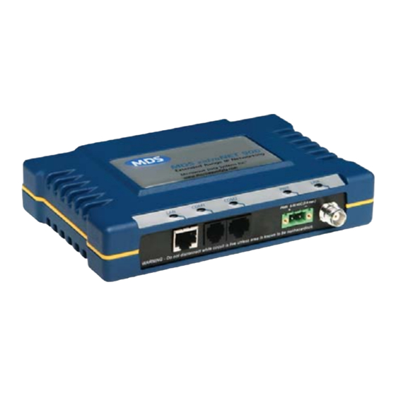
1.1 ABOUT THIS MANUAL This guide provides installation and operating instructions for the MDS entraNET 900 and MDS entraNET 2400 series radio system. The guide is intended for use by those who install, configure, and operate the entraNET wireless network. Quick Start instructions are provided on the inside front cover of this guide. - Page 12 Invisible place holder Access Point Remote Figure 1-1. MDS entraNET Transceiver Models MDS entraNET transceivers use an advanced Media Access Controller Robust Radio Operation (MAC) to ensure network access for stations with data to send. The MAC permits data to be sent from endpoint devices on an on-demand basis, preventing over-the-air data collisions and ensuring that data gets through as intended.
- Page 13 firmware, including data encryption, enabling or disabling remote access channels, and password protection. Remember, security is not a one-step process that can be simply turned on and forgotten. It must be practiced and enforced at multiple levels, every day. Section contains additional information about entraNET security features.
-
Page 14: Applications
1.2.1 Model Offerings The MDS entraNET system includes two primary radio types— APs and Remotes. Table 1-1 summarizes the interface capabilities for each entraNET radio type. NOTE: A Remote serves only one endpoint MAC address, even if a bridge or hub is used. Table 1-1. -
Page 15: Combining Serial And Ip Or Ethernet Devices
Invisible place holder Remote Remote Remote Remote Access Point Figure 1-2. Typical Wireless LAN System 1.3.2 Combining Serial and Ethernet Devices Prior to the introduction of the entraNET series, multiple networks were often needed to service different types of communication protocols. An entraNET system provides this functionality through a single AP radio. -
Page 16: Dnp3 Protocol-Aware Networks
including reduced management requirements when using MDS NETview Management System (MS) software. In addition, entraNET offers nearly unlimited potential for future applications that run over IP and Ethernet services. In an IP-to-serial scenario, every Remote is sent information received by the AP Ethernet port. -
Page 17: Upgrading An Older Wireless Network With Serial Interfaces
Millions of wireless data products have been sold in the last two decades for licensed and license-free operation, many of them manufactured by Microwave Data Systems. There are several ways that these systems can benefit from employing MDS entraNET wireless equipment, including flexible serial and Ethernet interfaces, higher data throughput, and ease of installation. -
Page 18: Mds Security Suite
Invisible place holder Figure 1-4. MDS P22 Protected Network Station (incorporates two MDS entraNET APs) 1.4 MDS SECURITY SUITE Today, the operation and management of an enterprise is becoming increasingly dependent on electronic information flow. An accompa- nying concern becomes the security of the communication infrastructure and the security of the data itself. -
Page 19: Intrusion Detection Via Snmp Traps
Table 1-2. Security Risk Management Security Risk The MDS entraNET Solution Airsnort and other war-driving intruders in Frequency-hopping spread parking lots, near buildings, etc. spectrum (FHSS) does not talk over the air with standard 802.11b cards The transceiver cannot be put in a “promiscuous”... -
Page 20: Accessories
1.5 ACCESSORIES MDS entraNET transceivers may be used with one or more of the acces- sories listed in Table 1-3. Contact MDS for ordering details. Table 1-3. Accessories Accessory Description MDS Part No. AC Power A small power supply module designed for 01-3682A02 Adapter Kit continuous service. - Page 21 Table 1-3. Accessories Accessory Description MDS Part No. Flat-Surface Brackets: 2˝x 3˝ plates designed to be screwed 82-1753-A01 Mounting onto the bottom of the radio for Brackets and surface-mounting the radio. Screws Screws: 6-32, 1/4˝ with locking adhesive. 70-2620-A01 (Industry Standard MS 51957-26) DIN Rail Bracket used to attach the transceiver to 03-4124A01...
- Page 22 MDS entraNET System Guide MDS 05-4055A01, Rev. C...
-
Page 23: Tabletop Setup And Evaluation
TABLETOP SETUP AND EVALUATION 2 Chapter Counter Reset Paragraph 2.1 INTRODUCTION 2.2 CONNECTOR OVERVIEW 2.3 TEST SETUP STEP 1—CONNECT THE ANTENNA PORTS ........ 19 STEP 2—MEASURE AND CONNECT DC POWER......19 STEP 3—CONFIGURE THE AP ............21 Log-in and Configuration ..............21 Set Key AP Parameters .............. - Page 24 MDS entraNET System Guide MDS 05-4055A01, Rev. C...
-
Page 25: Introduction
2.1 INTRODUCTION Prior to installation in the field, it is recommended that you set up the radio system in an office or lab and become familiar with its operation and features. This also allows tests of various network designs and con- figurations prior to arrival at a field site. -
Page 26: Test Setup
Invisible place holder ANTENNA 50Ω TNC +30 dBm/1W Out (Max.) –30 dBm Input (Max.) 10-Base-T IP/Ethernet Port IP Address: 192.168.0.1 PRIMARY POWER 6–30 Vdc (800 ma @ 13.8 Vdc) COM1 Negative Ground DCE (Console/Terminal only) 19,200 bps/8N1 No Handshaking RS/EIA-232 COM2 DCE (Connects to serial data equip.) -
Page 27: Test Setup
STEP 1—CONNECT THE ANTENNA PORTS Figure 2-3 is a drawing of a tabletop arrangement. Connect the antenna ports of each transceiver as shown through attenuators and an RF power divider. This provides for stable communications between each radio, while preventing interference to nearby electronic equipment. Invisible place holder Figure 2-3. - Page 28 Invisible place holder Lead Binding Screws (2) Wire Ports Figure 2-4. Power Connector (polarity: left +, right –) The transceiver must be used only with nega- CAUTION tive-ground systems. Make sure the polarity of the POSSIBLE POSSIBLE power source is correct. The radio is protected from EQUIPMENT EQUIPMENT DAMAGE...
- Page 29 Power Supply Common 28 Vdc supplies are often high-current power supplies Connections at 28 designed primarily to charge battery banks. The radio can be operated from these supplies, providing there are no transients on the leads as power is applied to the radio. Transients can be created that rise above 30 Vdc to a voltage that exceeds the primary voltage rating of the radio and can destroy its voltage regulators and other components.
-
Page 30: Step 3-Configure The Ap
STEP 3—CONFIGURE THE AP The instructions below summarize essential AP settings for tabletop testing. For detailed AP log-in and menu navigation instructions, see ACCESSING THE MENU SYSTEM on Page 36. Log-in and Configuration The AP must be configured first, as Remote transceivers depend on the AP beacon signal to achieve a connected (linked) state. -
Page 31: Step 4-Set Remote Configuration
a. Press the key to receive the prompt. The COM1 login ENTER LED flashes to indicate data communications. a. At the prompt, enter the username ( is the default login admin username). Press ENTER b. At the prompt, enter the password ( is the default Password admin... - Page 32 Table 2-1. Key AP Parameters and Defaults (Continued) Menu Item Management System Loca- Default Values or Range tion RF Output Main Menu >> 900 MHz: 30 dBm 900 MHz: 20–30 dBm Radio Configuration > Power 2.4 GHz: 27 dBm 2.4 GHz: 17-27 dBm (non-ETSI) RF Output Main Menu >>...
-
Page 33: Set Or Verify Network Address
Invisible place holder Invisible place holder Invisible place holder Invisible place holder Invisible place holder Figure 2-6. Remote Configuration Setup 3. Press several times to receive the prompt. (The entranet> ENTER COM1 LED blinks to indicate data communication.) 4. At the prompt, enter . -
Page 34: Step 5-Connect Terminal Equipment
With all radios connected, you are ready to connect data devices to the transceivers so that their operation can be tested over the wireless net- work. This is discussed in the next step. STEP 5—CONNECT TERMINAL EQUIPMENT This step describes connection of external data equipment to the Remote radio. -
Page 35: Serial Connections
LED Label Activity Indication COM1 Blinking Data TX or RX (MGT System) No data activity COM2 Blinking Data TX or RX No data activity Primary power (DC) present Blinking Radio in “Alarmed” state Primary power (DC) absent LINK (AP) Lights when radio has finished its startup cycle. - Page 36 MDS entraNET System Guide MDS 05-4055A01, Rev. C...
-
Page 37: Ap Management
AP MANAGEMENT 3 Chapter Counter Reset Paragraph 3.1 INTRODUCTION ............... 31 3.1.1 PC-Based Configuration Software ..........31 3.1.2 Menu Structure ................32 3.1.3 Differences in the User Interfaces ..........35 3.2 ACCESSING THE MENU SYSTEM .......... 36 3.2.1 Methods of Control ..............36 3.2.2 PC Connection and Log-In Procedures ........ - Page 38 3.7 SECURITY CONFIGURATION..........64 3.7.1 Security Configuration Menu ............65 3.8 WIRELESS NETWORK MENU ..........69 3.8.1 Remote Management Submenu ..........70 Manage Selected Remote Submenu..........71 Broadcast Remote Reprogramming Menu ........72 Endpoint Database Menu ..............74 Access Point Database Menu............75 3.9 STATISTICS AND EVENT LOG..........
-
Page 39: Pc-Based Configuration Software
3.1 INTRODUCTION The MDS entraNET AP embedded Management System (MS) is acces- sible through various data interfaces. These include the serial) COM1 ( port, Ethernet) port, and SNMP. Essentially the same capabilities LAN ( are available through any of these paths. For SNMP management, the transceiver is compatible with MDS NETview MS™... -
Page 40: Menu Structure
The commands for Remote radios are presented separately in CHAPTER 4 REMOTE RADIO MANAGEMENT, beginning on Page NOTE: Any parameter options, ranges, or default values are displayed at the end of the field description between square brackets. The default value is always shown last in a series of items. For example: Range, Options Description;... - Page 41 Invisible place holder MAIN MENU—Diagram 1 of 2 Starting Information Screen (read-only items) Network Security Local Serial Radio Remote Serial Configuration Configuration Configuration Configuration Gateway Figure 3-1. entraNET MS Menu Flowchart (diagram 1 of 2) MDS 05-4055A01, Rev. C MDS entraNET System Guide...
- Page 42 Invisible place holder MAIN MENU—Diagram 2 of 2 Starting Information Screen (read-only items) Wireless Network Redundancy Statistics/Event Log Device Maintenance/Tools DNP3 Routing Information Figure 3-2. entraNET MS Menu Flowchart (diagram 2 of 2) MDS entraNET System Guide MDS 05-4055A01, Rev. C...
-
Page 43: Differences In The User Interfaces
3.1.3 Differences in the User Interfaces There are slight differences in navigation between Telnet, terminal, and Web interfaces. Generally, the screen content is the same. There are minor differences in capabilities from limitations of the access channel. Below are samples of the Starting Information Screen as seen through a terminal session and a Web browser. -
Page 44: Accessing The Menu System
3.2 ACCESSING THE MENU SYSTEM The radio has no external controls. All configuration, diagnostics and control is performed electronically using a connected PC. This section explains how to connect a PC, log in to the radio, and access the built-in menu screens. -
Page 45: Pc Connection And Log-In Procedures
3.2.2 PC Connection and Log-In Procedures The following steps describe how to access the radio menu. These steps require a PC to be connected to the port on the radio, as COM 1 shown in Figure 3-5. To COM1 or LAN Port (See Text) Serial or Ethernet Crossover Cable... - Page 46 NOTE: If the radio is powered up or restarted while connected to a terminal, a series of pages of text relating to the startup of the internal microcomputer is displayed. Wait for the log-in screen before proceeding. 4. Press to receive the prompt.
- Page 47 NOTE: When using a Local Area Network (LAN) to access the radio, it may be necessary to change the computer IP access to the LAN in order to be compatible with the entraNET radio (compatible subnets). You can identify or verify the radio IP address by using a Local Console session to communicate with the entraNET radio through its port and viewing the...
- Page 48 Invisible place holder Figure 3-8. Starting Information Screen—Telnet Example NOTE: This method requires that you know the IP address of the radio Starting a Web Browser Session you are connecting to. If you do not know the address, start a Local Console session (see Starting a Local Console Session (recommended for first-time users)
- Page 49 Invisible place holder admin Figure 3-9. Log-in Page when using a Web Browser NOTE: Passwords are case sensitive. Do not use punctuation marks. You may use up to eight alphanumeric characters. 5. Click . The radio responds with a startup menu as in Figure 3-10.
-
Page 50: Navigating The Menus
3.2.3 Navigating the Menus Navigating via Terminal or Telnet Sessions Recommended for first-time users Local console and Telnet sessions use multi-layered text menu systems that are nearly identical. • To select a menu item, press the letter shown at the beginning of that item. -
Page 51: Basic Device Information
Log Out via Web Click on in the left-hand frame of the browser window. The Logout Browser right-hand frame changes to a log-out page. Follow the remaining instructions on this screen. This completes the instructions for connecting to the entraNET radio for PC configuration and control. -
Page 52: Main Menu
• — Shows current number of Remote radios Associated Remotes associated with the AP. • —User-definable string that can be used to identify the Location radio location (40 characters maximum). • —Unique identifier for this device. It must be pro- Serial Number vided to MDS when purchasing Authorization Keys to upgrade radio capabilities. -
Page 53: Configuring Network Parameters
• —Tools to configure the data connections Remote Serial Gateway to the Remote transceiver serial ports. (See “Remote Serial Gateway Configuration (IP-to-Remote Serial)” on Page 62.) • —Tools to configure the transceiver secu- Security Configuration rity services. (See “SECURITY CONFIGURATION” on Page 64.) •... -
Page 54: Ip Configuration Menu
Invisible place holder Figure 3-13. Network Configuration Menu (From Access Point) This menu is subdivided into the following sections: • —The transceiver IP address, netmask, and gate- IP Configuration way addresses. • —Parameters for the Media Access Wireless MAC Configuration Control (MAC) wireless protocol. - Page 55 Figure 3-14. IP Configuration Menu When static IP addressing is used, the user must manually configure the IP address and other parameters. When dynamic addressing is used, the radio uses a Dynamic Host Configuration Protocol (DHCP) Client pro- cess to obtain an IP address from a DHCP Server, along with other parameters such as a net mask and a default gateway.
-
Page 56: Wireless Mac Configuration Menu
• —Displays the IPv4 address of the default Current IP Gateway gateway device; typically a router. NOTE: The radio is not a router, so all IP parameters access local management only, and have no effect on the routing of system data. -
Page 57: Mobility Configuration Menu
3.4.4 Mobility Configuration Menu Invisible place holder Figure 3-16. Mobility Configuration Menu Invisible place holder • —This parameter controls intra-cell transmis- BSP Routing Enable sion and routing of Basic Serial Protocol packets.[ Enabled Dis- abled Disabled • —This parameter enables the Inter-Access Point IAPP Enable Protocol (IAPP), which allows APs to pass payload data over the Ethernet LAN. -
Page 58: Snmp Agent Configuration Menu
3.4.5 SNMP Agent Configuration Menu Invisible place holder Figure 3-17. SNMP Agent Configuration Menu Invisible place holder This menu provides configuration and control of SNMP functionality. • —The alphanumeric string that appears in the SNMP V3 Agent ID upper right-hand corner of the screen. The entry of this string is required in non-MDS SNMP manager programs (for example, SNMPc). -
Page 59: Bridge Configuration Menu
• —Current state of the authentication traps. [ Auth Trap Enable Dis- abled/Enabled; Disabled • —Determines whether v3 passwords are SNMP v3 Password Mode managed locally or via an SNMP Manager. The different behav- iors of the Agent, depending on the mode selected, are described above. -
Page 60: Configuring Radio Parameters
3.5 CONFIGURING RADIO PARAMETERS There are two primary data layers in the MDS entraNET network— radio (RF) and data. The data layer is dependent on the radio layer to work properly. The Radio Configuration Menu is the primary menu used to set radio parameters. This screen includes the Skip Zone Options Submenu. -
Page 61: Skip Zones Menu
• —Sets the maximum number of attempts Unicast Retry Count made to deliver point-to-point messages. Higher values are more reliable, but increase over-the-air congestion. [ 0-14; 10 • —Displays the current use of fre- (editable at AP only) Skip Zones quency zones. -
Page 62: Configuring The Serial Interfaces
Table 3-1 shows the frequency range covered by each zone for 900 MHz radios. Table 3-2 shows the same information for 2400 MHz radios. Table 3-1. Frequency Zones (900 MHz systems) ZONE 1 ZONE 2 ZONE 3 ZONE 4 ZONE 5 ZONE 6 ZONE 7 ZONE 8... -
Page 63: Serial-To-Serial Services
Invisible place holder Figure 3-21. Conceptual Views of Radio System Usage The AP includes an embedded terminal server that provides access to Remote serial ports via an IP or serial connection at the AP. In this capacity, it acts as a gateway between IP and remote serial devices (thus the name “serial gateway”), or a transparent over-the-air serial-to-serial connection. -
Page 64: Configuration
Most polled protocols are best served by UDP services, as the protocol itself has built-in recovery mechanisms (error correction). UDP pro- vides the needed multidrop operation by means of multicast addressing, where multiple remote devices receive and process the same poll message. -
Page 65: Local Serial Configuration Menu
3.6.2 Local Serial Configuration Menu Figure 3-22. COM1/2—Local Serial Configuration Menu • )—Defines whether the specified COM1 COM2 Port Status port is enabled or disabled to pass payload data. is typ- COM1 ically disabled to allow it to be used for console terminal control. - Page 66 Figure 3-23. Serial Configuration Wizard (Initial Screen) To start the Serial Configuration Wizard, choose . The Begin Wizard Wizard presents an opening screen (Figure 3-24) where you select the method the host computer uses to connect to the radio. Invisible place holder Figure 3-24.
-
Page 67: View Current Settings Screen-Serial-To-Serial Example
View Current Settings Screen—Serial-to-Serial Example If you choose from the Serial Configuration Wizard View Current Settings Menu, you see a summary screen (Figure 3-25) showing the serial con- figuration settings. (This is the same screen that is also shown at the end of the configuration process.) Here, you may choose the letter of an item to change, or exit the Serial Configuration Wizard completely. - Page 68 • —Set the method the host uses to connect to the radio. Mode Serial, Network; Network • —Specify the Remote(s) that transmissions are Remote UnitID directed to. Enter “broadcast” to send transmissions to all Remotes, or enter the Unit ID number of a particular Remote for unicast (directed) data.
-
Page 69: View Current Settings Screen-Unicast Udp Mode Example
View Current Settings Screen—Unicast UDP Mode Example Figure 3-26 shows a sample View Current Settings Screen for a system configured for Unicast UDP mode. The selections shown are similar to the serial-to-serial example above, but some items are UDP specific. Invisible place holder Figure 3-26. -
Page 70: Remote Serial Gateway Configuration (Ip-To-Remote Serial)
address and port number of the host to send data to (at the remote end). • —A dynamically assigned software port used by TX IP Port external applications such as HMI interfaces, host polling programs, etc. • —Used to enable or disable Talkback mode. Talkback Enable Enabled, Disabled;... - Page 71 Invisible place holder Figure 3-27. Remote Serial Gateway Menu—Initial Screen • (UDP IP-to-Serial)—When Talkback is RSG Talkback Enable enabled and the RSG is set up for UDP mode, a message from a Remote radio (usually a reply to a poll) is sent to the last IP address or port that a message was received from.
-
Page 72: Security Configuration
Invisible place holder Figure 3-28. Remote Serial Gateway (RSG) Entries Menu (TCP configuration; UDP is similar) • —Enter “Broadcast”, or enter the Unit ID of the Unit ID Remote for unicast (directed) data. The Unit ID defaults to the last four digits of the radio serial number, but can be set to any 32-bit integer. -
Page 73: Security Configuration Menu
NOTE: Security enhancements in entraNET 2.3.0 firmware necessi- tate that encryption must be turned prior to upgrading entraNET Remote radios with the new firmware. Failure to turn encryption off results in loss of communication between an AP and entraNET Remote radios. Once the firmware upgrade is complete, encryption may be re-enabled. - Page 74 • —Enables authentication of Remote radios Approve Remotes before granting access to the network. Enabling forces the entra- NET radio to check the Approved Remotes List (described below) before continuing the authorization process. Before enabling this option, at least one entry must already exist in the Approved Remotes List.
- Page 75 • —This selection invokes an immediate change Force Key Rotation in the encryption key. For this function to work, encryption must be enabled, a valid must be set, and key Encryption Phrase rotation must be enabled. Note that there is no feedback on the screen—the change takes place as soon as the menu selection is made.
- Page 76 Approved Remotes List Submenu Figure 3-31. Approved Remotes List Menu The AP restricts communication to only those Remotes included in the Approved Remotes List. Messages received from Remotes that are not in this list are discarded. • —Enter the Remote serial number. This Add Approved Remote entry must consist of seven or more characters.
-
Page 77: Wireless Network Menu
3.8 WIRELESS NETWORK MENU The Wireless Network Menu (Figure 3-32) monitors the operation of Remote radios in the network, regardless of the type of data they are passing (Ethernet or serial) from the perspective of the AP. This infor- mation is stored in a local database at the AP, and is not sent to the Remotes. -
Page 78: Remote Management Submenu
• —This selection is used to specify whether end- EndPoint Logging point logging is enabled or disabled. Enabled, Disabled; Enabled 3.8.1 Remote Management Submenu The Remote Management Menu (Figure 3-33) allows selection of a par- ticular Remote to manage, based on the radio Unit ID number (generally the last four digits of its serial number). -
Page 79: Manage Selected Remote Submenu
Manage Selected Remote Submenu Figure 3-34. Manage Selected Remote Menu • —Selecting this item brings up a submenu Device Information (Figure 3-36) where you may change a Remote radio Owner , and . Hardware and software version information, Name Location including the bootloader version, is also displayed. -
Page 80: Broadcast Remote Reprogramming Menu
Figure 3-35. Remote Reprogramming Menu (Single Remote) Invisible place holder • —This field shows the Unit ID of the Remote Remote to Manage to be managed. • —There are two available firmware Package (Image) to Transmit images in the AP. This allows selection of either image to be transmitted to the remote. - Page 81 Broadcast Broadcast reprogramming is used to upgrade the firmware of all radios reprogramming with in a network. If your network contains a mix of radios with 2.x and 3.x different firmware version firmware, it is normal to see the status message “Some Remotes versions on a Failed Programming”.
-
Page 82: Endpoint Database Menu
Invisible place holder Figure 3-37. Remote Database Menu • —The unit ID of the associated remote. UnitID • —Shows whether or not the Remote is connected to the Conn State • —Number of minutes until the entry expires and is removed AgeOut from the table. -
Page 83: Access Point Database Menu
Invisible place holder Figure 3-38. Endpoint Database Menu (Lists all equipment attached to Remote transceivers in the network) • —Ethernet address of the endpoint device. MAC Address • —Number of minutes until the device (address) is removed AgeOut from the table. Each transceiver maintains a table with the addresses of the devices it communicates with. -
Page 84: Statistics And Event Log
Invisible place holder Figure 3-39. Access Point Database • —Factory-assigned serial number for the AP. Serial Number • —IP Address of the AP. IP Address • —Current number of Remotes connected to Number of Remotes the AP. • —Lists all Remotes (by Unit ID number) that are List of Remotes currently connected to the AP. -
Page 85: Com1 And Com2 Data Statistics Menus
• —These screens show in and out bytes COM1/COM2 Data Statistics for the ports. COM1 COM2 • —Shows Unit ID, status, and Remote Serial Gateway Statistics throughput data for associated Remotes. • —Shows vital data on packets, in and out Ethernet Packet Statistics bytes, errors detected, and lost Ethernet carriers. -
Page 86: Remote Serial Gateway Statistics
3.9.2 Remote Serial Gateway Statistics The Remote Serial Gateway Statistics screen (Figure 3-42) summarizes port activity for Remote Serial Gateway entries that have been set up for IP-to-Remote serial data. These values are reset to zero when a radio is restarted. -
Page 87: Ethernet And Wireless Packet Statistics
3.9.3 Ethernet and Wireless Packet Statistics The Ethernet/Wireless Packet Statistics screen (Figure 3-43) shows vital data on packets and bytes sent or received, and errors detected. The screen is updated about every three seconds. Figure 3-43. Sample Packet Statistics Screen Ethernet Packet Statistics •... -
Page 88: Radio Packet Statistics
• —Packets that do not pass a Cyclic Redundancy Receive errors Check (CRC). This may be due to transmissions corrupted by RF interference. • —Resets the statistics counter. Clear Statistics 3.9.4 Radio Packet Statistics The previous screen dealt with Ethernet-related information. The Radio Packet Statistics screen (Figure 3-44) contains statistics that relate... -
Page 89: Event Log Menu
3.9.5 Event Log Menu The microprocessor within the transceiver monitors many operational parameters and logs them. Events are classified into four levels of importance, which are described in Table 3-3. Some of these events result from a condition that prevents the normal operation of the radio— these are “critical”... - Page 90 Invisible place holder Figure 3-46. View Event Log Screen Invisible place holder • —Purges the log of all stored events. Clear Event Log TIP: Save your Event Log before clearing it to retain poten- tially valuable troubleshooting information. See USING CONFIGURATION SCRIPTS on Page 177 for an over- view on how to transfer files from the transceiver to a...
-
Page 91: Device Information Menu
3.10 DEVICE INFORMATION MENU The Device Information menu (Figure 3-47) displays basic administra- tive data on the radio to which you are connected. It also provides a date and time display, Console Baud Rate setting, and customer-specific parameters under the Device Names selection. Invisible place holder Figure 3-47. -
Page 92: Maintenance And Tools
Device Names Menu Figure 3-48. Device Names Menu • —Device Name, used by the transceiver as the Device Name realm name for network security and menu headings. • —Customer defined; appears on this screen only. Contact • —Customer defined; appears on this screen only. Location •... -
Page 93: Reprogramming Menu
• Authorization Codes (Keys)—Alter the radio capabilities by enabling the built-in resources via purchased keys. See “ Authorization Codes Menu” on Page 90 • Transmitter Test—Diagnostic commands for RF transmitter. See “ Transmitter Test Menu” on Page Figure 3-49. Maintenance/Tools Menu 3.11.1 Reprogramming Menu The AP transceiver has two copies of the firmware (microprocessor code) used for the operating system and applications. -
Page 94: Configuration Scripts Menu
Figure 3-50. Reprogramming Menu • —IP address of the host computer from which TFTP Host Address to get the file. [ Any valid IP address • —Name of file to be received from the TFTP Firmware Filename server. Verify that this string corresponds to the TFTP directory location. - Page 95 (data file). However, only a few essential parameters need to be reviewed and altered to use the file with another transceiver. A configuration file makes it easy to apply your unique settings to any transceiver(s) you wish. Configuration files also provide you with a tool to restore parameters to a known working set, in the event that a param- eter is improperly set and performance is affected.
-
Page 96: Rsg Configuration Script Menu
3.11.3 RSG Configuration Script Menu The RSG Configuration Script Menu (Figure 3-52) is used to manage the download of configuration script files for the transceiver. Invisible place holder Figure 3-52. RSG Configuration Script Menu • —This is the IP address of the host com- RSG Config Host Address puter. -
Page 97: Ping Utility Menu
PING Utility Menu The PING Utility Menu (Figure 3-53) is used to verify IP connectivity with LAN nodes or Ethernet endpoints. Figure 3-53. PING Utility Menu • —Address to send a Address to Ping PING Any valid IP address • —Number of packets to be sent. -
Page 98: Authorization Codes Menu
3.11.4 Authorization Codes Menu Figure 3-54. Authorization Codes Menu • —Accept an Authorization Key into the trans- Authorization Key ceiver non-volatile memory. • —Presents a list of authorized (display only) Authorized Features features. At the time of publication, available features include MDS NETview MS and DNP3 Handling. -
Page 99: Transmitter Test Menu
3.11.5 Transmitter Test Menu This screen (Figure 3-55) allows testing of the radio transceiver RF transmitter section (power amplifier). Selections of specific frequencies and key duration, as well as transmit key behavior, can be modified from this screen. This function is useful for troubleshooting specific radio amplifier issues. -
Page 100: Redundancy Menu
3.12 REDUNDANCY MENU Redundancy is available only at the AP. The Redundancy Menu (Figure 3-56) is used in protected installations where a backup trans- ceiver can be immediately placed online if a primary radio fails. This protects against “single point of failure” scenarios. The Redundancy Menu contains selections and settings that are used to manage redun- dancy functions. - Page 101 Invisible place holder Figure 3-57. Network Event Triggers Menu • —This selection presents a submenu (see Hardware Event Triggers Figure 3-58) with parameters related to local alarm conditions. Invisible place holder Figure 3-58. Hardware Event Triggers Menu • —This selection presents a sub- Redundancy Configuration Options menu (see Figure...
- Page 102 Figure 3-59. Redundancy Configuration Options Menu • —This selection invokes an immediate switcho- Force Switchover ver from the active to the standby radio. Invisible place holder • —This selection is used to enable or dis- Network Interface Error able redundancy switchover on the occurrence of a Network Interface Error.
-
Page 103: Packet Rx Errors Exceeded Threshold Menu
Invisible place holder Figure 3-60. Lack of Assoc. Remotes Exceeded Threshold Menu • —This selection brings Packet Receive Errors Exceeded Threshold up another screen (see Packet Rx Errors Exceeded Threshold Menu below) where you can specify the number of packet errors that must be exceeded in a given time frame before a redundant AP considers itself to be malfunctioning. -
Page 104: Dnp3 Routing Menu
These configuration settings are intended for data-intensive applications and must be customized for your specific application. —Here, you specify the number of packet errors Maximum Receive Errors that must be exceeded before a redundant AP considers itself to be mal- functioning. - Page 105 • —Specifies the IP port number used for all DNP Multicast Port DNP3 Multicast messaging. [ 0-65535; 20000 • —This field specifies the IP port number used to DNP Unicast Port establish a socket to other IP devices. This UDP port (along with the AP local IP address) is used to encapsulate DNP3 messages over IP.
- Page 106 MDS entraNET System Guide MDS 05-4055A01, Rev. C...
-
Page 107: Remote Radio
REMOTE RADIO MANAGEMENT 4 Chapter Counter Reset Paragraph 4.1 INTRODUCTION ..............101 4.2 Programming Methods ............101 4.2.1 Terminal Interface Mode ............101 4.2.2 Remote Management via the AP ..........101 4.3 Log-in Procedure ..............101 4.4 Commands ................102 4.4.1 Entering Remote Commands ............102 4.5 Minimum Configuration for Remotes ........ - Page 108 MDS entraNET System Guide MDS 05-4055A01, Rev. C...
-
Page 109: Introduction
4.1 INTRODUCTION Local configuration of Remote transceivers is performed through a PC terminal connected to the port of the radio. This section explains COM1 how to establish a console session with the Remote, and provides a com- plete list of commands. 4.2 Programming Methods 4.2.1 Terminal Interface Mode A PC program such as HyperTerminal may be used to establish a ter-... -
Page 110: Commands
2. At the prompt, enter your username ( is the default). username admin is the default). 3. At the prompt, enter your password ( Password admin 4.4 Commands Table 4-1 provides a quick reference to the various commands for the Remote transceiver. -
Page 111: Detailed Command Descriptions
Table 4-1. Remote Commands—Quick Reference COMMAND DESCRIPTION COMMAND DESCRIPTION When entered after a command in this list, HELP Lists commands supported for the logged-in (after a com- shows detailed information and allowable user. (See also the command at the begin- mand) entries ning of this table.) - Page 112 —Configures a list of approved APs. is a number from APx=<integer> 1–50, and is the serial number of an approved AP (1–99999999). integer To delete an entry, enter a serial number of 0; this indicates that the slot is not filled. Serial Number of approved AP AP1=<integer>...
- Page 113 defaults to command-line mode COM1 CONSOLE defaults to transparent data mode COM1 DATA defaults to in Basic Serial Protocol mode COM1 defaults to internal loopback mode COM1 INT_LOOP defaults to external loopback mode COM1 EXT_LOOP —Sets or displays the port data characters, COM1 FORMAT=<format>...
- Page 114 measured inter-packet delay can increase up to one dwelltime (7,14, or 28 ms) period. COM2 Sets or displays the COM2 port configuration. Optional arguments: —Sets or displays baud rate setting as 1200, 2400, 4800, BAUD=<bps> 9600, 19200, 38400, 57600, or 115200 bps. —Sets or displays the port maximum buffer size COM2...
- Page 115 —Sets or displays the transceiver inter-packet gap status. INTERGAP Optional arguments: —For incoming or outgoing serial data —For incoming serial data only —For incoming or outgoing (low latency) serial data —For incoming (low latency) serial data only —Switches the console port among various interface MODE=<mode>...
- Page 116 —(read only) Displays the product name. PRODUCT —(read only) Displays the software revision ID. —Sets or displays the owner information (1-40 ASCII charac- OWNER ters). —Sets or displays the radio name (1-40 ASCII characters). NAME —Sets or displays the radio location (1-40 ASCII characters). LOCATION —(read only) Displays the current system uptime in the format UPTIME...
- Page 117 : 7 milliseconds : 14 milliseconds : 28 milliseconds —Sets operation to Direct or Infrastructure mode. MODE=<mode> : Enter Direct mode : Enter Infrastructure mode : Enter Direct mode by external control —Sets or displays the network (system) address NETADDR=<netaddr> (0-30000) when in direct mode.
- Page 118 —Sets or displays the data encryption mode. MODE=<ON|OFF> : Data encryption on : Data encryption off —Sets or displays the Encryption Pass Phrase (8–41 PHRASE=<string> characters). —Displays all settable optional arguments and their current values. You can copy this list to a text file as a record of your configuration. Sets or displays the configuration of the Ethernet port.
- Page 119 —The hand-off threshold for ACK averaging ACKAVGTHRESH=<percent> (1–99). —Sets or displays the time in seconds (0–255) to BLOCKTIME=<seconds> block access to an AP after hand-off. —Displays all settable optional arguments and their current values. You can copy this list to a text file as a record of your configuration. —Number of hand-offs that occurred.
- Page 120 —Show the event log SHOW —Number of event log entries in log. Read only. TOTAL= —Displays all settable optional arguments and their current values. You can copy this list to a text file as a record of your configuration. LOGIN This command is used for secure log-in to the radio.
- Page 121 : Tor 1 Image TOR1 : Tor 2 Image TOR2 RADIO Sets or displays the radio configuration and status. Optional arguments: —(read only) Displays the associated AP Serial Number. —(read only) Displays whether or not the Remote radio has ASSOC= been associated with an AP.
- Page 122 —Restarts the radio with Application Image 1 APP1 —Restarts the radio with Application Image 2 APP2 SLEEP Sets or displays the low-power operating mode. These modes are com- monly used where power consumption must be kept to a minimum, such as in solar-powered installations.
- Page 123 AP. These monitoring packets are sent out every time there is over-the-air traffic. This command is designed to work with the MDS Mobility Application available from Microwave Data Systems (Part No. 06-4157A01). Optional arguments: : Turns the Stattracker function on : Turns the Stattracker function off MDS 05-4055A01, Rev.
-
Page 124: Upgrading Remote Firmware
: Allowable range of port numbers that may be entered 30000–60000 —Displays all settable optional arguments and their current values. You can copy this list to a text file as a record of your configuration. Displays the current software version information. Optional arguments: —Displays all settable optional arguments and their current values. - Page 125 A brief description of each screen item is given below. • —Allows exiting the utility. File • —Here, you can select to extract S28 files, display the Options debugging log, or show file versions. • —Shows the copyright and version information. Help •...
- Page 126 MDS entraNET System Guide MDS 05-4055A01, Rev. C...
-
Page 127: Sample
SAMPLE CONFIGURATIONS 5 Chapter Counter Reset Paragraph 5.1 INTRODUCTION ..............121 5.1.1 IP-to-Local Serial Application Example ........121 5.1.2 IP-to-Remote Serial Application Example .........122 Endpoint Device Connected to the AP ...........123 5.1.3 Point-to-Point, Serial-to-Serial Application Example ....124 Step-by-step instructions for configuring a point-to-point serial connection................125 5.1.4 Point-to-Multipoint, Serial-to-Serial Application Example ..132 Step-by-step instructions for configuring a point-to-... - Page 128 MDS entraNET System Guide MDS 05-4055A01, Rev. C...
-
Page 129: Introduction
5.1 INTRODUCTION This chapter provides details of how radios should be configured and connected for specific applications, such as IP-to-serial and serial-to-serial configurations. Only the most relevant parameters are shown for the sake of simplicity. All other parameters are assumed to be set at their default values. -
Page 130: Ip-To-Remote Serial Application Example
Table 5-1. IP-to-Local Serial Port Application Configuration IP-to-local serial connection (Local Serial Gateway) Radio Location Menu Item Setting AP (COM2) Port Status Enabled Mode RX IP Port 30011 Baud Rate 19200 Byte Format Buffer Size 256 Bytes 5.1.2 IP-to-Remote Serial Application Example This configuration makes any data sent or received with the AP via an IP port number appear via the serial port of a single Remote (or of all Remotes, if “Broadcast”... -
Page 131: Endpoint Device Connected To The Ap
Endpoint Device Connected to the AP In this arrangement, information received via an AP Ethernet port is sent to the serial port of the Remotes and the AP local serial port. The reverse is also true, meaning that any data received from the serial port of any Remote or the AP local serial port is encapsulated into an IP packet and sent out the AP Ethernet port. -
Page 132: Point-To-Point, Serial-To-Serial Application Example
5.1.3 Point-to-Point, Serial-to-Serial Application Example Once the transceivers are configured and the changes have been exe- cuted, they begin processing any data presented at the ports. Data presented at the AP port is packetized and sent over the air via a proprietary protocol to the Remote. -
Page 133: Step-By-Step Instructions For Configuring A Point-To-Point Serial Connection
Step-by-step instructions for configuring a point-to-point serial connection 1. Connect a powered AP radio to a PC. 2. At the PC, open a connection with the Access Point radio using a terminal, Telnet, or Web browser session. 3. Press to display the Main Menu. 4. - Page 134 Figure 5-6. Port Configuration Setting 6. Press to start the Serial Configuration Wizard. Figure 5-7. Begin the Serial Configuration Wizard MDS entraNET System Guide MDS 05-4055A01, Rev. C...
- Page 135 7. The first screen of the Serial Configuration Wizard prompts for the connection type. Press to select “Serial”. Figure 5-8. Connection Type Selection Screen 8. The Wizard displays a prompt to select a point-to-point or point-to-multipoint connection. Press to select “One Remote” (point-to-point).
- Page 136 9. The Wizard displays a prompt for the Unit ID of the single Remote radio. Press to set the Remote ID (generally the last four digits of the Remote serial number). Type the Unit ID of the Remote radio. Press to accept the Unit ID.
- Page 137 baud rate options until “19200” is displayed. Press to accept ENTER the Data Baud Rate. Press to set the Data Byte Format. Press to cycle through SPACE the byte format options until “8N1” is displayed. Press ENTER accept the Data Byte Format. Then press to continue.
- Page 138 the options until “4 Character Times” is displayed. Press ENTER accept the Inter Frame Delay. Then press to continue. Figure 5-13. Set Buffer Size and Inter Frame Delay 13.The next screen prompts for the Port Status. Press to select Port Status.
- Page 139 • COM2 Remote Unit ID: [Unit ID displayed] • COM2 Remote COM Port: COM2 • COM2 Baud Rate: 19200 • COM2 Byte Format: 8N1 • COM2 Buffer Size: 256 Bytes • COM2 Inter Packet Delay: 4 Character lines Figure 5-15. Final Configuration Settings Display If the settings shown on screen match the ones listed above, press to commit the changes and exit the Serial Configuration Wizard.
-
Page 140: Point-To-Multipoint, Serial-To-Serial Application Example
In the future, if you need to set up another radio or make changes, you can go directly to this screen by pressing instead of in step 5 above. Figure 5-16. View Current Settings 5.1.4 Point-to-Multipoint, Serial-to-Serial Application Example The operation and data flow for this mode is very similar to a point-to-point serial-to-serial application, except that it uses multicast addressing. -
Page 141: Step-By-Step Instructions For Configuring A Point-To- Multipoint Serial Connection
Invisible place holder Figure 5-17. Point-to-Multipoint Serial-to-Serial Diagram Table 5-5. Point-to-Multipoint Serial-to-Serial Configuration MDS entraNET radio Menu Item Setting Location AP (COM2) Port Status Enabled Mode Serial-to-Serial Remote UnitID Broadcast Remote COM port COM2 Baud Rate 19200 Byte Format Buffer Size 256 Bytes Inter-Packet Delay Remote radio (COM2) - Page 142 4. From the Main Menu, press to select Local Serial Configuration. Figure 5-18. Main Menu 5. The Local Serial Configuration menu displays the status of the AP ports (enabled or disabled). Set the port to COM1 COM2 COM2 “enabled”. Press to select , then press to toggle between...
- Page 143 6. Press to start the Serial Configuration Wizard. Figure 5-20. Begin the Serial Configuration Wizard 7. The first screen of the Serial Configuration Wizard prompts for the connection type. Press to select “Serial”. Figure 5-21. Connection Type Selection Screen MDS 05-4055A01, Rev. C MDS entraNET System Guide...
- Page 144 8. The Wizard displays a prompt to select a point-to-point or point-to-multipoint connection. Press to select “All Remotes” (broadcast). Figure 5-22. Point-to-Multipoint Selection 9. The next screen prompts for the input serial data port. Press then press to toggle to COM2 .
- Page 145 10.The next screen prompts for the baud rate and byte format. Press to set the Data Baud Rate. Press to cycle through the SPACE baud rate options until the baud rate for your equipment is dis- played. (In the example below, the baud rate is 19200.) Press ENTER to accept the Data Baud Rate.
- Page 146 Figure 5-25. Set Buffer Size and Inter Frame Delay 12.The next screen prompts for the Port Status. Press to select Port Status. Press to toggle between “enabled” and “disabled”. SPACE Press when “enabled” is displayed. Then press to continue. ENTER Figure 5-26.
- Page 147 • COM2 Remote Unit ID: broadcast • COM2 Remote COM Port: COM2 • COM2 Baud Rate: 19200 • COM2 Byte Format: 8N1 • COM2 Buffer Size: 256 Bytes • COM2 Inter Packet Delay: 4 Character lines Figure 5-27. Final Configuration Settings Display If the settings shown on screen match the ones listed above, press to commit the changes and exit the Serial Configuration Wizard.
-
Page 148: Mixed-Mode Application Example
In the future, if you need to set up another radio or make changes, you can go directly to this screen by pressing instead of in step 5 above. Figure 5-28. View Current Settings 5.1.5 Mixed-Mode Application Example In this configuration, the Host PC can use both TCP and serial-to-serial data paths to reach the endpoint devices. - Page 149 • All communication paths can be used simultaneously. Figure 5-29. Mixed Modes Application Diagram Table 5-6. Serial Port Application Configuration MDS entraNET Menu Item Setting radio Location AP (COM2) Port Status Enabled Mode Serial-to-Serial Remote UnitID Broadcast Remote COM Port COM2 Baud Rate 19200...
- Page 150 MDS entraNET System Guide MDS 05-4055A01, Rev. C...
-
Page 151: Installation
INSTALLATION 6 chapter Counter reset Paragraph 6.1 INSTALLATION ................ 145 6.1.1 General Requirements ..............145 6.1.2 Site Selection ................145 6.1.3 Conducting a Site Survey ............146 Terrain and Signal Strength ............146 A Word About Radio Interference ...........146 Mounting Dimensions for Radios............148 6.1.4 Antenna and Feedline Selection ..........149 Antennas ..................149 Feedlines ..................150 ......................151... - Page 152 MDS entraNET System Guide MDS 05-4055A01, Rev. C...
-
Page 153: Installation
6.1 INSTALLATION This section provides tips for selecting an appropriate site, choosing an antenna system, and reducing the chance of harmful interference. 6.1.1 General Requirements There are three main requirements for installing a transceiver—ade- quate and stable primary power, a good antenna system, and the correct interface between the transceiver and the data device. -
Page 154: Conducting A Site Survey
6.1.3 Conducting a Site Survey If you are in doubt about the suitability of the radio sites in your system, it is best to evaluate them before a permanent installation is begun. This can be done with an on-the-air test (the preferred method); or indirectly, using path-study software. - Page 155 some level of interference should be expected. However, flexible design and hopping techniques should allow adequate performance, as long as care is taken in choosing station location, configuration of radio param- eters, and software or protocol techniques. In general, keep the following points in mind when setting up your com- munications network: •...
-
Page 156: Mounting Dimensions For Radios
Mounting Dimensions for Radios Figure 6-2 shows the dimensions of the AP transceiver with mounting brackets attached. Figure 6-3 shows the same view for a Remote trans- ceiver. When mounting entraNET transceivers, choose a location that provides easy access to the connectors on the end of the radio and an unobstructed view of the LED status indicators. -
Page 157: Antenna And Feedline Selection
Invisible place holder Step 1: Attach the bracket using the Step 2: Snap the assembly onto the the two screws provided. (Attach to DIN rail. To remove the radio, the end opposite the connectors.) pull down on the release tab. Figure 6-4. -
Page 158: Feedlines
Invisible place holder High-gain Type Unity-gain Type Figure 6-5. Typical Omnidirectional Antennas At remote sites, and for radios in point-to-point LANs, a directional Yagi (Figure 6-6) antenna is generally recommended to minimize inter- ference to and from other radio systems. Antennas are available from a number of manufacturers. - Page 159 For 900 MHz systems with cable runs of less than 20 ft./6m, an inexpen- sive cable type such as Type RG-8A/U may be acceptable. For longer runs, or for 2400 MHz systems, we recommend using a low-loss cable type such as Andrew Corp. HELIAX cable.
-
Page 160: How Much Output Power Can Be Used
6.2 HOW MUCH OUTPUT POWER CAN BE USED? (U.S.A. and Canada, 900 MHz systems) 900 MHz transceivers are normally supplied from the factory set for +30 dBm (1 Watt) RF power output; this is the maximum transmitter output power allowed under FCC and Industry Canada rules. The power must be decreased from this level if the antenna system gain exceeds 6 dBi. -
Page 161: How Much Output Power Can Be Used
gain of 6 dB or less entitles you to operate the radio at full power output 30 dBm (1 Watt). Table 6-4. Antenna System Gain versus Power Output Setting (U.S.A. and Canada only) Antenna System Gain Maximum Power (Antenna Gain in dBi* Setting EIRP minus Feedline Loss in dB†) -
Page 162: How Much Output Power Can Be Used? (Etsi 2400 Mhz Systems)
1. Determine the antenna system gain by subtracting the feedline loss (in dB) from the antenna gain (in dBi). For example, if the antenna gain is 10 dBi, and the feedline loss is 2 dB, the antenna system gain is 8 dB. 2. -
Page 163: Calculating System Gain
NOTE: Some EU countries mandate lower power outputs and frequency limitations from those referenced here. For example, in France, the transceiver may only be operated in band C (2.4528-2.4782 GHz) at a power level of 10 dBm. Be sure to check the requirements for your region before placing the transmitter on the air. -
Page 164: Optimizing Performance
6.5 OPTIMIZING PERFORMANCE After the basic operation of the radio has been established, you may wish to optimize network performance using some of the suggestions in this section. The effectiveness of these techniques vary with the design of your system and the format of the data being sent. There are two major areas for possible improvement—the radio and the data network. - Page 165 • The number of bytes they can fit into a hop, depending on hop time, is: Table 6-1. Number of bytes per hop Hop time (MS) Bytes/hop Included in the byte count is 9 bytes of overhead per packet. So, at 7MS without FEC, a 1000 byte packet requires 1009 bytes split into 45 bytes/hop, or 23 hops.
-
Page 166: Aiming Directive Antennas For Maximum Rssi
6.5.2 Aiming Directive Antennas for Maximum RSSI The wireless network integrity depends, in a large part, on stable radio signal levels being received at each end of a data link. In general, signal levels stronger than –90 dBm provides the basis for reliable communi- cation that includes a 15 dB fade margin. -
Page 167: Tips For Improving Data Throughput
6. View the counts at the point of maximum Radio Retries No Ack RSSI level. They should be the same or lower than the previous reading. (Main Menu > Performance Information > Packet Statistics > Wireless Packet Statistics) If the RSSI peak results in an increase in the Radio Retries No Ack counts, the antenna may be aimed at an undesired signal source. -
Page 168: To Maximize Overall Data Performance
NOTE: Reprogramming does not work over the air when the settings are used at the AP. Hop Time Encryption To Maximize Overall Data Performance • Change the for serial ports to the maximum of 1500. Buffer Size Longer packets are sent over the air, reducing overhead. On the down side, if a packet is corrupted, it takes longer to be retransmitted. -
Page 169: Troubleshooting And Radio Tests
TROUBLESHOOTING AND RADIO TESTS 7 Chapter Counter Reset Paragraph 7.1 TROUBLESHOOTING ............. 163 7.1.1 Interpreting the Front Panel LEDs ..........163 7.1.2 Troubleshooting Using the Embedded Management System ...164 Serial Port and Remote Serial Statistics Menu.......167 Diagnostic Tools................167 7.1.3 Using Logged Operation Events ..........168 MDS 05-4055A01, Rev. - Page 170 MDS entraNET System Guide MDS 05-4055A01, Rev. C...
-
Page 171: Troubleshooting
7.1 TROUBLESHOOTING Successful troubleshooting of a wireless system is not difficult, but requires a logical approach. It is best to begin troubleshooting at the AP radio, as the rest of the system depends on the AP for synchronization data. If the AP has problems, the operation of the entire wireless net- work is affected. -
Page 172: Troubleshooting Using The Embedded Management System
Table 7-1. Symptom-Based Troubleshooting Using LEDs Symptom Possible Cause and Resolution PWR LED does not a. The voltage is too low, or is the wrong polarity. Check for turn on. the proper supply voltage at the power connector (6–30 Vdc). See Figure 2-4 on Page 20 for polarity details. - Page 173 may be used remotely to provide preliminary diagnostic information, or may even provide a path to correcting the problem. Table 7-3. Troubleshooting with the Embedded Management System Symptom Possible Cause and Resolution Remote does not a. Verify that the AP has a sufficiently large number in the associate “Max Remotes”...
- Page 174 Table 7-3. Troubleshooting with the Embedded Management System (Continued) Symptom Possible Cause and Resolution Cannot pass IP a. Verify the AP IP settings. data to the WAN. b. Use the PING command to test communication with the AP and endpoints connected to Remote radios in the local radio system.
-
Page 175: Serial Port And Remote Serial Statistics Menu
The most significant fields are , and Retries Retry Errors Receive Errors . If the data values are more than 10% of their sent Lost Carrier Detected and received counterparts, or the value is greater Lost Carrier Detected than a few dozen, there may be trouble with interference, or a loss of the Ethernet signal. -
Page 176: Using Logged Operation Events
7.1.3 Using Logged Operation Events (See Event Log Menu on Page 81) The transceiver microprocessor monitors many operational parameters and logs them as various classes of “events.” If the event is one that affects performance, it is an “alarmed” event. There are also normal or routine events such as those marking the restarting of the system, imple- mentation of parameter changes, and external access to the entraNET MS. - Page 177 Table 7-5. MDS entraNET Event Codes Index Event Type Event Name Clear String Set String String EVENT_RAD_RX_TIMEOUT RX Timeout Cleared EVENT_RAD_NVMEM_FAULT NV Memory Cleared Fault EVENT_RAD_NOT_CALIBRATED TOR Not Cleared Calibrated EVENT_RAD_OUT_OF_LOCK Locked Out of Lock Synthesizer EVENT_RAD_AUTHORIZATION_ Authorization Cleared FAULT Fault EVENT_RAD_HARDWARE_ TOR Hardware...
- Page 178 Table 7-5. MDS entraNET Event Codes Index Event Type Event Name Clear String Set String String EVENT_DHCP_ADDRESS Obtained DHCP Address EVENT_TIME_NOT_SET Date or time Not EVENT_TIME_BY_USER Date or time Changed by User EVENT_TIME_FROM_SERVER Date or time from Server EVENT_CONSOLE_LOGIN Console User Logged Out Logged In EVENT_CONSOLE_LOCKDOWN...
- Page 179 Table 7-5. MDS entraNET Event Codes Index Event Type Event Name Clear String Set String String EVENT_REDUND_RECV_ERR Redundant Switchover Switchover Packet Receive EVENT_REDUND_FORCED Forced Switchover Switchover Redundant EVENT_ICOPY_STARTED Image Copy Started EVENT_ICOPY_COMPLETE Image Copy Complete EVENT_ICOPY_FAILED Image Copy Failed EVENT_ENDPOINT_ADDED Endpoint Removed Added...
- Page 180 MDS entraNET System Guide MDS 05-4055A01, Rev. C...
-
Page 181: Technical Reference
TECHNICAL REFERENCE 8 Chapter Counter Reset Paragraph 8.1 UPGRADING AP FIRMWARE..........175 8.2 USING CONFIGURATION SCRIPTS ........177 Sample of an Exported Configuration File........178 Editing Configuration Files..............182 8.3 DATA INTERFACE CONNECTORS......... 183 8.3.1 LAN/ETH Port ................183 8.3.2 COM1 Port ................184 8.3.3 COM2 Port ................185 8.4 TECHNICAL SPECIFICATIONS .......... - Page 182 MDS entraNET System Guide MDS 05-4055A01, Rev. C...
-
Page 183: Upgrading Ap Firmware
8.1 UPGRADING AP FIRMWARE MDS occasionally offers upgrades to the transceiver firmware. One ver- sion of the firmware provides core software resources for all radio models. Uploading new firmware into the radio does not alter any priv- ileges provided by Authorization Keys, and does not require the trans- ceiver to be taken offline until you want to operate the radio from the new firmware image in the radio. - Page 184 Invisible place holder LOCAL PC WITH FIRMWARE FILES ACCESS POINT Figure 8-1. Upgrade Configuration—Option 1 (TFTP Server and Firmware File on Same CPU) Invisible place holder REMOTE PC W/FIRMWARE FILES TFTP SERVER ACCESS POINT LOCAL PC Figure 8-2. Upgrade Configuration—Option 2 (TFTP server and firmware file on remote server) NOTE: Transferring the radio firmware image file, which is about 3 MB, may take several minutes, depending on traffic between...
-
Page 185: Using Configuration Scripts
Upgrade Procedure To upgrade the transceiver firmware file ( ), use the proce- filename.gpk dure below. 1. Launch a TFTP server on a PC connected either directly or via a LAN to the transceiver Ethernet port ( ). Configure the server to allow downloads from the directory containing the firmware image file. -
Page 186: Sample Of An Exported Configuration File
same profile. Ultimately, standardized files can be uploaded into the transceiver to speed up the installation process. Configuration files can also be uploaded into a transceiver to restore the settings of a radio using a previously saved configuration of the radio. This is particularly convenient after finishing a test using some experi- mental settings. - Page 187 The radio model number. This value is set at the factory and cannot be changed. Serial Number: 1026295 The radio serial number. This value is set at the factory and cannot be changed. Unit Name: Library Admin Office A name for this radio. It appears at the top of every menu screen. Owner: Hilltop College MIS The name of the owner of this radio.
- Page 188 Company Name: MDS Version Name: 06-1234567 Product Name: entraNET RF Output Power Setpoint: 30 The desired amount of RF output power, measured in dBm. Active Boot Image: 0 Skipped Hop Zone1: Active Skipped Hop Zone2: Skip Skipped Hop Zone3: Active Skipped Hop Zone4: Active Skipped Hop Zone5: Active Skipped Hop Zone6: Active...
- Page 189 Setting to enable SNMP authentication traps. Trap Version: v1 Traps The SNMP trap format. Package 1 Version: 1.1.0 Indicates the version of firmware in Image 1. Package 2 Version: 1.1.0 TFTP Timeout: 20 COM1 Serial Data Enable: disabled Setting to enable the data mode.
-
Page 190: Editing Configuration Files
Number of output characters buffered in inter-packet delay for COM1. Com2 Serial Data Buffer Size: 20 RF Frequency Hopping Format: USA or CANADA (read only) The frequency-hopping rules the radio is configured to operate under. SNMP Enable: disabled Enable or disable the SNMP agent. Approved Remotes List Enable: disabled Enable or disable the Approved Remotes List. -
Page 191: Data Interface Connectors
Each resulting file should be saved with a different name. We recom- mend using directories and file names that reflect the location of the radio to facilitate its identification. Editing Rules • You may include only parameters you want to change. •... -
Page 192: Com1 Port
The connector uses standard Ethernet RJ-45 cables and wiring. The pinout graphic and table below may be used to construct a custom cable, if required. 1 2 3 4 5 6 7 8 Figure 8-3. LAN/ETH Port (RJ-45) Pinout (viewed from the outside of the radio) Functions Ref. -
Page 193: Technical Specifications
8.3.3 COM2 Port A terminal device may be connected to the transceiver port COM2 (RJ-45) for payload data connection. Pinout information for the COM2 port is provided in Figure 8-5 Table 8-3. 1 2 3 4 5 6 7 8 Figure 8-5. - Page 194 Time Required for Remote to Connect with AP: typically less than 1 second RADIO CHARACTERISTICS System Gain: 2400 MHz: 131 dB 900 MHz: 136 dB Carrier Power: 900 MHz: 20-30 dBm 2400 MHz: 20-27 dBm 2400 MHz ETSI: 10-20 dBm Output Impedance: 50 Ohms Occupied Bandwidth:...
- Page 195 TRANSCEIVER MANAGEMENT Methods Supported (AP): • HTTP (embedded Web server)—pending • Telnet • Local console via COM1 port • SNMPv1/2/3. MIB II, Enterprise MIB—pending • SYSLOG • MDS NETview MS —pending Methods Supported (Remote): Local console via COM1 port ENVIRONMENTAL Temperature Range: -40C to +70C (-33.8F to +158F) Humidity:...
- Page 196 Shutdown (all remotes): 0.37 mA at 6 Vdc 0.55 mA at 12 Vdc 0.78 mA at 30 Vdc MECHANICAL Case: Cast aluminum Mounting Options: Flat surface mount brackets, 35 mm DIN rail Dimensions (Excluding mtg. hardware): AP: 3.15 H x 17.2 W x 11.2 D cm (1.25 H x 6.75 W x 4.5 D in.) Remote: 2.5 x 12.7 x 8.9 cm (1 H x 5 W x 3.5 D in.)
-
Page 197: Dbm-Watts-Volts Conversion Chart
8.5 dBm-WATTS-VOLTS CONVERSION CHART Table 8-4 is provided as a convenience for determining the equivalent voltage or wattage of an RF power expressed in dBm. Table 8-4. dBm-Watts-Volts Conversion—for 50 ohm systems dBm V dBm V dBm mV dBm µV 100.0 200W .225 1.0mW... - Page 198 MDS entraNET System Guide MDS 05-4055A01, Rev. C...
-
Page 199: Terms And Abbreviations
TERMS AND ABBREVIATIONS 9 Chapter Counter Reset Paragraph 10 Chapter Counter Reset Paragraph If you are new to wireless IP or Ethernet systems, some of the terms used in this guide may be unfamiliar. The following glossary explains many of these terms and is helpful in understanding the operation of the trans- ceiver system. - Page 200 DCE—Data Communications Equipment. In data communications ter- minology, this is the “modem” side of a computer-to-modem connec- tion. The transceiver ports are set as DCE. COM1 COM2 Decibel (dB)—A measure of the ratio between two signal levels. Fre- quently used to express the gain (or loss) of a system. DES—Data Encryption Standard.
- Page 201 FHSS—Frequency Hopping Spread Spectrum. A common transmission technique used by license-free transceivers. Frame—A segment of data that adheres to a specific data protocol and contains definite start and end points. It provides a method of synchro- nizing transmissions. Frequency Hopping—The spread spectrum technique used by the transceivers, where two or more associated radios change their oper- ating frequencies several times per second using a set pattern.
- Page 202 Latency—The delay (usually expressed in milliseconds) between when data is applied at the transmit port at one radio, until it appears at the receive port at the other radio. MAS—Multiple Address System. A radio system where a central master station communicates with several remote stations for the pur- pose of gathering telemetry data.
- Page 203 Poll—A request for data issued from the host computer (or master PLC) to a Remote radio. Portability—Refers to the ability of a transceiver to connect to an AP from multiple locations without the need to reconfigure the network set- tings. For example, a transceiver located in one place and connected to an AP can be turned off, moved to another place, turned back on;...
- Page 204 SWR—Standing-Wave Ratio. A parameter related to the ratio between forward transmitter power and the reflected power from the antenna system. As a general guideline, reflected power should not exceed 10% of the forward power (≈ 2:1 SWR). TCP—Transmission Control Protocol. A “guaranteed delivery” pro- tocol used to set up a connection between two devices with acknowl- edgements (ACK/NACK), and retries if the data is not received properly.
- Page 205 Antenna MCU (Microcontroller Unit), defined 194 selection 149 Multiple Address System (MAS) system gain vs. power output setting, table 153, 154, 155 defined 194 Yagi, illustrated 150 network, illustrated 7 BPS (bits-per-seond), defined 191 Network address Byte, defined 191 defined 194 Network configuration commands 103 Network-wide diagnostics defined 194...
- Page 206 MDS entraNET System Guide MDS 05-4055A01, Rev. B...
- Page 207 The radio must be properly packed for return to the factory. The original shipping container and packaging materials should be used whenever possible. All factory returns should be addressed to: Microwave Data Systems Product Services Department (SRO No. XXXX)
- Page 208 Microwave Data Systems Inc. 175 Science Parkway Rochester, NY 14620 General Business: +1 585 242-9600 FAX: +1 585 242-9620 Web: www.microwavedata.com A product of Microwave Data Systems Inc.
Need help?
Do you have a question about the MDS entraNET 900 and is the answer not in the manual?
Questions and answers