
Related Manuals for MDS 2710D


Summary of Contents for MDS 2710D
- Page 1 Microwave Data Systems Inc. MDS 1710 A/C MDS 2710A/C/D Data Transceiver MDS 05-3447A01, REV. F SEPTEMBER 2004...
- Page 2 QUICK START GUIDE Below are the basic steps for installing the transceiver. Detailed instructions are provided in “Installation Steps” on Page 9 of this manual. Install and connect the antenna system to the radio • Use good quality, low loss coaxial cable. Keep the feedline as short as possible. •...
-
Page 3: Table Of Contents
BAUD [xxxxx abc] ................. 23 BUFF [ON, OFF]................23 CKEY [ON–OFF] ................24 CTS [0–255] ................. 24 DATAKEY [ON, OFF] ..............24 DEVICE [DCE, CTS KEY] ............24 DKEY .................... 25 MDS 05-3447A01, Rev. F MDS 1710A/C and MDS 2710A/C/D... - Page 4 7.4 Helical Filter Adjustment ..............37 7.5 Upgrading the Radio’s Software ............. 38 Using Radio Software Upgrade Diskette ........38 Using Radio Configuration Software..........39 7.6 dBm-Watts-Volts Conversion Chart ..........40 MDS 1710A/C and MDS 2710A/C/D MDS 05-3447A01, Rev. F...
- Page 5 This Installation and Operation Guide and all software described herein are protected by copyright: © 2004 Microwave Data Systems Inc . All rights reserved. MDS reserves its right to correct errors and omissions. To Our Customers We appreciate your patronage. You are our business. We promise to serve and anticipate your needs.
- Page 6 FCC Approval Notice At the printing date, MDS 1710 models are approved for operation in the USA from150 to 174 MHz. MDS 2710 models are approved for opera- tion in the USA from 216 to 222 MHz. Contact MDS for current approval status.
- Page 7 Customer Service Team using the information at the back of this guide. In addition, manual updates can often be found on the MDS Web site at www.microwavedata.com. Microwave Data Systems Inc.
- Page 8 MDS 1710A/C and MDS 2710A/C/D MDS 05-3447A01, Rev. F...
-
Page 9: General
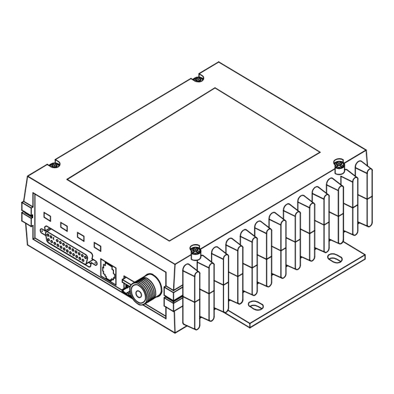
1.0 GENERAL 1.1 Introduction This guide presents installation and operating instructions for MDS 1710A/C and MDS 2710 A/C/D series digital radio transceivers. These transceivers (Figure 1) are data telemetry radios designed to operate in a point-to-multipoint environment, such as electric utility... -
Page 10: Differences Between Models
1.2 Differences Between Models All models of the MDS 1710/2710 Series are very similar in appearance and functionality. The major differences are in frequency coverage, channel bandwidth and data speed. -
Page 11: Point-To-Point System
Figure 3. It provides a simplex or half-duplex communications link for the transfer of data between two locations. HOST COMPUTER MASTER REMOTE Figure 3. Typical Point-to-Point Link MDS 05-3447A01, Rev. F MDS 1710A/C and MDS 2710A/C/D... -
Page 12: Continuously Keyed Versus Switched Carrier Operation
The master station is always simultaneously transmitting and continuously listening. Different frequencies must be used for transmit and receive. NOTE: MDS 1710/2710 radios do not support full-duplex operation. Therefore, switched carrier mode must be set to ON ( SWC ON... -
Page 13: Accessories
1.5 Accessories The transceiver can be used with one or more of the accessories listed in Table 2. Contact Microwave Data Systems for ordering information. Table 2. MDS 1710/2710 Series Optional Accessories Accessory Description MDS P/N Hand-Held Terminal Terminal that plugs into the radio for... - Page 14 DTE—Data Terminal Equipment. A device that provides data in the form of digital signals at its output. Connects to the DCE device. Equalization—The process of reducing the effects of amplitude, fre- quency or phase distortion with compensating networks. MDS 1710A/C and MDS 2710A/C/D MDS 05-3447A01, Rev. F...
- Page 15 Microcontroller Unit—See MCU. Multiple Address System—See MAS. Network-Wide Diagnostics—An advanced method of controlling and interrogating MDS radios in a radio network. Non-intrusive diagnostics—See Passive messaging. Passive messaging—This is a mode of diagnostic gathering that does not interrupt SCADA system polling communications. Diagnostic data is collected non-intrusively over a period of time;...
-
Page 16: Installation
There are three main requirements for installing the transceiver—ade- quate and stable primary power, a good antenna system, and the correct data connections between the transceiver and the data device. Figure 5 shows a typical remote station arrangement. MDS 1710A/C and MDS 2710A/C/D MDS 05-3447A01, Rev. F... -
Page 17: Installation Steps
Refer to the complete list of pin functions provided in Table 4 on page 4. Measure and install the primary power for the radio. The red wire on the power cable is the positive lead; the black is negative. MDS 05-3447A01, Rev. F MDS 1710A/C and MDS 2710A/C/D... - Page 18 After programming, the HHT ENTER reads to indicate successful entry. PROGRAMMED OK • Set other transceiver parameters as required. A complete list of transceiver commands is provided in Section 5.0, TRANSCEIVER PROGRAMMING. MDS 1710A/C and MDS 2710A/C/D MDS 05-3447A01, Rev. F...
-
Page 19: Transceiver Mounting
Yagi (Figure 7) or corner reflector antenna is generally recom- mended at remote sites to minimize interference to and from other users. Antennas of this type are available from several manufacturers. MDS 05-3447A01, Rev. F MDS 1710A/C and MDS 2710A/C/D... -
Page 20: Feedlines
2.5 amperes of continuous current. The red wire on the power cable is the positive lead; the black is nega- tive. NOTE: The radio is designed for use only in negative ground systems. MDS 1710A/C and MDS 2710A/C/D MDS 05-3447A01, Rev. F... -
Page 21: Data Interface Connections
Connect this line to Pin 12 of the radio’s connector. This will allow each RTU to DATA INTERFACE be polled once per hour with a significant savings in power con- sumption. MDS 05-3447A01, Rev. F MDS 1710A/C and MDS 2710A/C/D... - Page 22 Excessive drain on this connection will trip self-resetting fuse F1 on the transceiver PC board. The voltage at this pin will match the input voltage to the transceiver. MDS 1710A/C and MDS 2710A/C/D MDS 05-3447A01, Rev. F...
-
Page 23: Operation
HHT connected to the radio’s DIAG. RSSI connector.—See Section 5.0, TRANSCEIVER PROGRAMMING. This can also be done with a DC voltmeter as described in Section 4.2, RSSI Measurement. MDS 05-3447A01, Rev. F MDS 1710A/C and MDS 2710A/C/D... -
Page 24: Led Indicators
DC voltage on Pin 21 of the DATA INTER- connector. (Note: Readings are not accurate for signals stronger FACE than –50 dBm.) Invisible place holder SIGNAL LEVEL (dBm) Figure 8. RSSI vs. Vdc (Typical) MDS 1710A/C and MDS 2710A/C/D MDS 05-3447A01, Rev. F... -
Page 25: Transceiver Programming
Contact MDS for ordering information. 5.1 Hand-Held Terminal Connection & Startup This section gives basic information for connecting and using the MDS Hand-Held Terminal. For more information about the terminal, refer also to the instructions included with each HHT kit. -
Page 26: Hand-Held Terminal Setup
2. The first of 15 menu items is displayed. Settings are reviewed by pressing the NEXT function controlled by the key. Parameter set- tings are changed by pressing the ROLL function controlled by the key. MDS 1710A/C and MDS 2710A/C/D MDS 05-3447A01, Rev. F... -
Page 27: Keyboard Commands
—The command was not recognized. Refer to the UNKNOWN COMMAND command description for command usage information. —The command format or its associated values were INCORRECT ENTRY not valid. Refer to the command description for command usage infor- mation. MDS 05-3447A01, Rev. F MDS 1710A/C and MDS 2710A/C/D... - Page 28 — The command was unable to write to EEPROM. EEPROM FAILURE INIT This is a serious internal radio error. Contact MDS for assistance. Table 7. Command summary Command name Function AMASK [0000 Set or display hex code identifying which events 0000–FFFF FFFF]...
- Page 29 INIT [2710] Restores certain transceiver defaults before using Details page 26 the INIT xx20 command. INIT [2720] Configure radio for use with an MDS model P-20 Details page 26 chassis. Key the radio (transmitter ON). This is generally Details page 27 used for radio testing.
-
Page 30: Detailed Command Descriptions
Table 8 on page 32 for a list of event codes.) The hex value for the mask corresponds to the hex value for the command STAT (see the command description). STAT MDS 1710A/C and MDS 2710A/C/D MDS 05-3447A01, Rev. F... -
Page 31: Asense [Hi/Lo]
For more information on tailoring the alarm response, contact the MDS Technical Services Department. ASENSE [HI/LO] command sets or displays the sense of the alarm output at... -
Page 32: Ckey [On-Off]
, the radio needs to be keyed by asserting either the RTS or PTT signal or with the command. CKEY DEVICE [DCE, CTS KEY] command sets or displays the device behavior of the radio. DEVICE The command parameter is either CTS KEY MDS 1710A/C and MDS 2710A/C/D MDS 05-3447A01, Rev. F... -
Page 33: Dkey
DTYPE See “Performing Network-Wide Remote Diagnostics” on page 34. Two associated commands are . See MDS’ Network-Wide GATE PEER Diagnostics System Handbook (MDS P/N 05-3467A01) for details. MDS 05-3447A01, Rev. F MDS 1710A/C and MDS 2710A/C/D... -
Page 34: Dump
+37 dBm (5 watts) All other commands stay at their previously established settings. INIT [2710] This command sets the transceiver for operation outside the MDS model P-20 chassis by setting the following parameters as shown. ASENSE ACTIVE HI... -
Page 35: Key
This command displays the radio’s model number code. MODEM [xxxx, NONE] This command selects the radio’s modem characteristics. Enter 9600 or 3200 for digital operation, or enter NONE to select analog operation. For MDS 1710 digital operation the proper settings are for the MDS 9600 2710A, for the MDS 1710C. -
Page 36: Rssi
RX [xxx.xxxxx] This command selects or displays the radio’s receive frequency in MHz. The frequency step size is 6.25 kHz for the MDS 2710A/C and 5.0 kHz for the MDS 2710D. If the customer frequency has not been programmed at the factory, a default frequency will be programmed in the radio near the center of the frequency band. -
Page 37: Show [Dc, Port, Pwr]
ENTER key. Detailed descriptions of event codes are provided in Table 8 on page TEMP This command displays the internal temperature of the transceiver in degrees Celsius. MDS 05-3447A01, Rev. F MDS 1710A/C and MDS 2710A/C/D... -
Page 38: Tot [1-255, On, Off]
TX [xxx.xxxxx] This command selects or displays the radio’s transmit frequency in MHz. The frequency step size is 6.25 kHz for the MDS 2710A/C and 5.0 kHz for the MDS 2710D. If the customer frequency has not been programmed at the factory, a default frequency will be programmed in the radio near the center of the frequency band. -
Page 39: Led Indicators
(or seriously degrade) further operation of the transceiver. Major alarms generally indicate the need for factory repair. Contact MDS for further assistance. MDS 05-3447A01, Rev. F MDS 1710A/C and MDS 2710A/C/D... -
Page 40: Event Code Definitions
27, 28 Not used Minor The transceiver’s internal temperature is approaching an out-of-tolerance condition. If the temperature drifts outside of the recommended operating range, system operation may fail. MDS 1710A/C and MDS 2710A/C/D MDS 05-3447A01, Rev. F... -
Page 41: Technical Reference
50 ohms Frequency Stability: MDS 1710 ±1.0 ppm MDS 2710 ±1.5 ppm Channel Spacing: 6.25 kHz steps (MDS 1710A/C and 2710A/C) 5.0 kHz steps (MDS 2710D) 6.25 kHz (MDS 1710A/C @ 130-174 MHz) Transmitter Spurious Radiated Emissions: –57 dBm, 30 MHz to 1 GHz –47 dBm, 1 GHz to 12.5 GHz... -
Page 42: Performing Network-Wide Remote Diagnostics
RJ-11 (may use radio’s DB-25 instead if Pin 23 is grounded to enable diagnostics channel) I/O Devices: MDS Hand Held Terminal or PC with MDS software 7.2 Performing Network-Wide Remote Diagnostics Diagnostics data from a remote radio can be obtained by connecting a laptop or personal computer running MDS InSite diagnostics software to any radio in the network. - Page 43 DTYPE ROOT radio. A complete explanation of remote diagnostics can be found in MDS’ Network-Wide Diagnostics System Handbook (MDS P/N 05-3467A01). See the Handbook for more information about the basic diagnostic procedures outlined below.
-
Page 44: Bench Testing Setup
5. Connect same-site radios using a null-modem cable at the radios’ diagnostic ports. 6. Connect a PC on which MDS InSite software is installed to the root radio, or to one of the nodes, at the radio’s diagnostic port. (This PC... -
Page 45: Helical Filter Adjustment
4. Measure the radio’s RSSI using one of the following methods: • With an HHT (See Section 5.0, TRANSCEIVER PROGRAM- MING on page 17). • With MDS Radio Configuration Software (See Section 7.5, Upgrading the Radio’s Software on page 38). • With a voltmeter connected to Pin 21 of the... -
Page 46: Upgrading The Radio's Software
DIAG. Upgrade software can be obtained in a number of ways. The MDS Web site at www.microwavedata.com contains an FTP area with software files for several radio models. You can browse the listings to see if there are files pertaining to your particular model. -
Page 47: Using Radio Configuration Software
Using Radio Software Upgrade Diskette A software upgrade diskette may be purchased from MDS to add new product features to the radio such as Network-wide Diagnostics. The upgrade kit includes a diskette (MDS P/N 06-3501A01) with the most current radio software, authorization codes, and an instruction booklet. -
Page 48: Dbm-Watts-Volts Conversion Chart
2.85 10.0 -136 10mW -137 2.25 .1µW -138 6.4mW .001nW -139 .500 -140 .01ƒW .445 5.75 .400 3.2mW .355 2.5mW 1.25 .320 2.0mW 1.18 .280 1.6mW 1.00 3.51 .252 1.25mW 0.90 MDS 1710A/C and MDS 2710A/C/D MDS 05-3447A01, Rev. F... - Page 49 ASENSE (set alarm output state) BAUD (set/display rate, encoding) BUFF (set/display data handling mode) pinout (Pin 8) CKEY (enable/disable continuous keying) DCE (Data Cirtuit-terminating Equipment), defined CTS (set/display CTS line response timer) Decibel (dB), defined MDS 05-3447A01, Rev. F MDS 1710A/C and MDS2710A/C/D...
- Page 50 RTU (RTU command) Hand-Held Terminal (HHT) connected to transceiver network-wide diagnostics (DLINK command) Hand-Held Terminal (HHT) reinitialization display network-wide diagnostics, procedures Hand-Held Terminal display in response to STAT command Environment specifications helical filter locations MDS 1710A/C and MDS2710A/C/D MDS 05-3447A01, Rev. F...
- Page 51 MAS network displaying (MODEL command) MDS 2710A/D model number codes MDS 2710A/D, illustrated network-wide diagnostics MODEM command point-to-point link Modem, set speed. See MODEM command remote station arrangement RJ-11 to DB-9 adapter cable 13, 16 RSSI vs. Vdc transceiver connectors & indicators...
- Page 52 RTS pinout (Pin 4) command summary conversions, dBm-Watts-Volts command data interface connector pinouts RTU (Remote Terminal Unit) defined Hand-Held Terminal (HHT) operational settings remote reset (Pin 15) LED status indicators MDS 1710A/C and MDS2710A/C/D MDS 05-3447A01, Rev. F...
- Page 53 30–32 Troubleshooting connecting Hand-Held Terminal (HHT) for displaying alarm codes performing network-wide diagnostics STAT command (Status) using PC software for TX command TXD LED description Pin 2 UNKNOWN COMMAND error message MDS 1710A/C and MDS2710A/C/D MDS 05-3447A01, Rev. F...
- Page 54 NOTES MDS 1710A/C and MDS2710A/C/D MDS 05-3447A01, Rev. F...
- Page 55 No equipment will be accepted for repair without MDS products are designed for long life and an SRO number. trouble-free operation. However, this equip- ment, as with all electronic equipment may A statement should accompany the radio have an occasional component failure.
- Page 56 Microwave Data Systems Inc. 175 Science Parkway Rochester, NY 14620 General Business: +1 585 242-9600 FAX: +1 585 242-9620 Web: www.microwavedata.com A product of Microwave Data Systems Inc.
Need help?
Do you have a question about the 2710D and is the answer not in the manual?
Questions and answers