MDS iNET 900 Installation Manual
Hide thumbs
Also See for iNET 900:
- User manual (130 pages) ,
- Installation manual (24 pages) ,
- User manual (190 pages)
Table of Contents
Advertisement
Quick Links
CONTENTS
OPERATIONAL & SAFETY NOTICES ...................................2
PRODUCT DESCRIPTION .....................................................4
INSTALLATION PLANNING ....................................................5
INSTALLATION .......................................................................5
Step 1-Mount the Transceiver ...................................................5
Step 2-Install the Antenna ........................................................6
Step 3-Measure & Install Primary Power ..................................6
Step 5-Connect the Data Equipment ........................................6
Step 6-Check for Normal Operation .........................................9
Performance Optimization .........................................................10
USING RSSI TO AIM REMOTE ANTENNAS .......................10
Method 1-For New Network Installations ................................11
Method 2-Adding iNET units to an existing network ...............13
TROUBLESHOOTING ..........................................................14
FUSE REPLACEMENT PROCEDURE ................................16
iNET SPECIFICATIONS .......................................................17
TECHNICAL ASSISTANCE ..................................................18
FACTORY SERVICE .............................................................18
INSTALLATION REFERENCE CHART ............. (Center Insert)
Copyright Notice
This publication is protected by U.S.A. copyright law. Copyright 2002, Microwave
Data Systems, Inc. All rights reserved.
MDS 05-2873A01, Rev. A
MDS iNET 900 Installation Guide
1
Advertisement
Table of Contents

Related Manuals for MDS iNET 900


Summary of Contents for MDS iNET 900
-
Page 1: Table Of Contents
TECHNICAL ASSISTANCE ..........18 FACTORY SERVICE .............18 INSTALLATION REFERENCE CHART ..... (Center Insert) Copyright Notice This publication is protected by U.S.A. copyright law. Copyright 2002, Microwave Data Systems, Inc. All rights reserved. MDS 05-2873A01, Rev. A MDS iNET 900 Installation Guide... -
Page 2: Operational & Safety Notices
National Electrical Code. 3. Installation, operation and maintenance of the transceiver should be in accor- dance with the transceiver's installation manual, and the National Electrical Code. MDS iNET 900 Installation Guide MDS 05-2873A01, Rev. A... - Page 3 Division 2 wiring methods. FCC Notice, U.S.A. The MDS iNET 900 transceivers comply with Part 15 of the FCC Rules. Operation is subject to the following two conditions: (1) this device may not cause harmful inter- ference, and (2) this device must accept any interference received, including interfer- ence that may cause undesired operation.
-
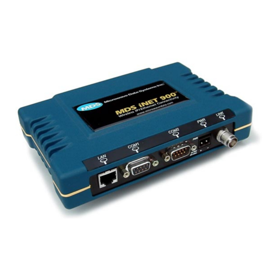
Page 4: Product Description
3. LAN port provides access to Management System on all models and varia- tions. The MDS iNET 900 transceivers serve as either an “Access Point” or “Remote”. An Access Point (AP) is a wireless hub that usually pro- vides connectivity into a wired Ethernet LAN/WAN. From a radio perspective, an Access Point also serves as the radio network’s... -
Page 5: Installation Planning
Should further information be required, see “TECHNICAL ASSIS- TANCE” on page 18 of this manual for information on contacting the MDS Customer Service Department. You will also find support infor- mation at the Microwave Data System Web site at www.microwave- data.com on the Internet. -
Page 6: Step 2-Install The Antenna
General information on the selection and installation of antenna systems is pro- vided in the MDS iNET 900 Network Manager’s Manual. Radio frequency energy generated by the i NET 900 can NOTE:... -
Page 7: Step 4-Review The Radio's Configuration
They are: • Device Mode —Access Point, or Remote (Default) • Network Name—Unique name of the iNET 900 units asso- ciated with the network (Required) The Network Name must be programmed to enable i NET 900 Remote units to associate with the Access Point unit. - Page 8 The Management System supports the use of “configuration scripts” which can hold complex parameter arrangements. These scripts aid in uniformly configuring multiple i NET units. These are detailed in the MDS iNET 900 Network Administrator’s Handbook . Basic i NET Configuration Defaults The Basic Configuration Defaults table on the Installation Reference Chart provides a summary of selected operating parameters’...
-
Page 9: Step 6-Check For Normal Operation
Step 6—Check for Normal Operation The first priority is to check the basic operation of data communica- tions between MDS i NET 900 units in the network. When that seems OK, connect the user data equipment and verify its proper operation through the iNET network. -
Page 10: Performance Optimization
Remote locations becomes necessary. Directional antennas usually require some fine-tuning of their bearing to optimize the received signal strength. The MDS iNET 900 unit has a built-in received signal strength indicator (RSSI) that can be used to tell you when the antenna is in a position that provides the optimum received signal. -
Page 11: Method 1-For New Network Installations
The test mode and your ability to change operating parameters will time-out after 10 minutes. You do not need to login again to continue to navigate through the Management System. You will MDS 05-2873A01, Rev. A MDS iNET 900 Installation Guide... - Page 12 Main Menu>Diagnostic Tools>Radio Test>RSSI 6. Optimize RSSI (less negative) by adjusting direction of antenna. 7. Turn off Radio Test Mode at the Access Point Main Menu>Diagnostic Tools>Radio Test>Test Mode>Disable End of procedure MDS iNET 900 Installation Guide MDS 05-2873A01, Rev. A...
-
Page 13: Method 2-Adding Inet Units To An Existing Network
RSSI level. The BER should be the same or better than the previ- ous reading. If not, the antenna may be aimed at an undesired sig- nal source. Main Menu>Performance Information>Bit-Error Rate End of procedure MDS 05-2873A01, Rev. A MDS iNET 900 Installation Guide... -
Page 14: Troubleshooting
(proper cable wiring, data format and timing). Table 2 on page 15 provides suggestions for resolving common system difficulties. If problems persist, review the MDS Web site’s technical support area for recent software/firmware updates, general troubleshooting help, and service information. Additional help is available through the MDS Customer Service Department. - Page 15 If successful with local PING, attempt to PING an IP unit attached to an iNET radio. c. If successful with the LAN PINGs, try connecting to a known unit in the WAN. MDS 05-2873A01, Rev. A MDS iNET 900 Installation Guide...
-
Page 16: Fuse Replacement Procedure
Littelfuse P/N: 0454002; 452 Series, 2 Amp SMF Slo-Blo (MDS P/N: 29-1784A03) 8. Replace the covers, interface cables and check the iNET unit for proper operation. Invisible place holder Figure 2. Fuse Location MDS iNET 900 Installation Guide MDS 05-2873A01, Rev. A... -
Page 17: Inet Specifications
Double conversion superheterodyne –92 dBm @ 512 kbps < 1x10 - Sensitivity: –100 dBm @ 256 kbps < 1x10 - Time Required to Synchronize with Access Point: < 1.4 minutes after boot (typical) MDS 05-2873A01, Rev. A MDS iNET 900 Installation Guide... -
Page 18: Technical Assistance
Microwave Data Systems’ Web site at www.microwavedata.com. FACTORY SERVICE If return of the equipment is necessary, please contact the MDS Cus- tomer Support Team. You will be issued a Returned Material Autho- rization (RMA) number. The RMA number will help expedite the repair so that the equipment can be repaired and returned to you as quickly as possible. - Page 19 MDS 05-2873A01, Rev. A MDS iNET 900 Installation Guide...
- Page 20 MDS iNET 900 Installation Guide MDS 05-2873A01, Rev. A...
Need help?
Do you have a question about the iNET 900 and is the answer not in the manual?
Questions and answers