
Related Manuals for MDS MDS 4710 Series


Summary of Contents for MDS MDS 4710 Series
- Page 1 MDS 4710/9710 Series (Including MDS 4710A/C and MDS 9710 A/C) 400 MHz/900 MHz Remote Data Transceiver MDS 05-3305A01, Rev. B SEPTEMBER 2000...
- Page 2 QUICK START GUIDE Below are the basic steps for installing the transceiver. Detailed instructions are given in “INSTALLA- TION” on page 9 of this guide. Install and connect the antenna system to the radio • Use good quality, low loss coaxial cable. Keep the feedline as short as possible. •...
-
Page 3: Table Of Contents
BAUD [xxxxx abc] ................23 BUFF [ON, OFF]................24 CKEY [ON–OFF] ................24 CTS [0–255] ..................24 DATAKEY [ON, OFF] ................ 24 DEVICE [DCE, CTS KEY] ..............25 DKEY....................25 DLINK [ON/OFF/xxxx] ..............25 MDS 05-3305A01, Rev. B MDS 4710/9710 I/O Guide... - Page 4 Major Alarms vs. Minor Alarms............32 Event Code Definitions ..............32 7.0 TECHNICAL REFERENCE ............33 7.1 MDS 4710/9710 Transceiver Specifications ........33 7.2 Helical Filter Adjustment ..............36 7.3 Performing Network-Wide Remote Diagnostics ......37 7.4 Upgrading the Radio’s Software ............. 38 7.5 dBm-Watts-Volts Conversion Chart ..........
-
Page 5: Copyright Notice
ISO 9001 Registration Microwave Data Systems' adheres to this internationally accepted quality system standard. MDS Quality Policy Statement We, the employees of Microwave Data Systems Inc., are committed to achieving total customer satisfaction in everything we do. Total Customer Satisfaction in: •... - Page 6 Refer to Articles 500 through 502 of the National Electrical Code (NFPA 70) for further information on hazardous locations and approved Division 2 wiring methods. MDS 4710/9710 I/O Guide MDS 05-3305A01, Rev. B...
- Page 7 Customer Service Team using the information at the back of this guide. In addition, manual updates can often be found on the MDS Web site at www.microwavedata.com.
- Page 8 MDS 4710/9710 I/O Guide MDS 05-3305A01, Rev. B...
-
Page 9: General
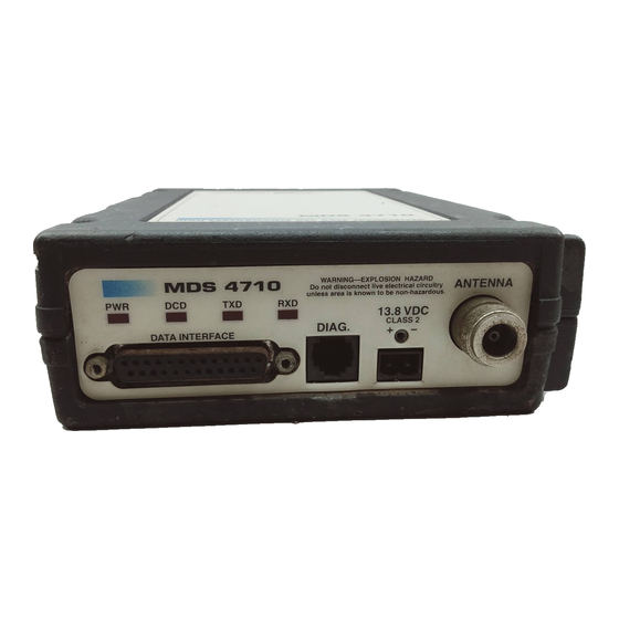
1.0 GENERAL 1.1 Introduction This guide presents installation and operating instructions for the MDS 4710/9710 Series (400/900 MHz) digital radio transceivers. These transceivers (Figure 1) are data telemetry radios designed to operate in a point-to-multipoint environment, such as electric utility... -
Page 10: Applications
REMOTE RADIO SWC OFF REMOTE RADIO SWC OFF REMOTE RADIO REMOTE RADIO SWC OFF CONTINUOUSLY SWC OFF KEYED REMOTE RADIO SWC OFF MDS MASTER HOST SYSTEM STATION Figure 2. Typical MAS Point-to-Multipoint Network MDS 4710/9710 I/O Guide MDS 05-3305A01, Rev. B... -
Page 11: Point-To-Point System
The radio model number is printed on the end of the radio enclosure, and provides key information about how the radio was configured when it was shipped from the factory. See Figure 4 and Figure 5 for an explana- tion of the model number characters. MDS 05-3305A01, Rev. B MDS 4710/9710 I/O Guide... -
Page 12: Accessories
*Not Available with FCC or IC Figure 5. 9710 Model Number Codes 1.4 Accessories The transceiver can be used with one or more of the accessories listed in Table 1. Contact Microwave Data Systems for ordering information. MDS 4710/9710 I/O Guide MDS 05-3305A01, Rev. B... - Page 13 Table 1. MDS 4710/9710 Optional Accessories Accessory Description MDS P/N Hand-Held Terminal Terminal that plugs into the radio for 02-1501A01 Kit (HHT) programming, diagnostics & control. Includes carrying case and cable set. RTU Simulator Test unit that simulates data from a 03-2512A01 remote terminal unit.
-
Page 14: Glossary Of Terms
DCE—Data Circuit-terminating Equipment (or Data Communications Equipment). In data communications terminology, this is the “modem” side of a computer-to-modem connection. The MDS 4710/9710 is a DCE device. Digital Signal Processing—See DSP. MDS 4710/9710 I/O Guide... - Page 15 DSP—Digital Signal Processing. In the MDS 4710/9710 transceiver, the DSP circuitry is responsible for the most critical real-time tasks; pri- marily modulation, demodulation, and servicing of the data port. DTE—Data Terminal Equipment. A device that provides data in the form of digital signals at its output. Connects to the DCE device.
- Page 16 Network-Wide Diagnostics—An advanced method of controlling and interrogating MDS radios in a radio network. Non-intrusive diagnostics—See Passive messaging. Passive messaging—This is a mode of diagnostic gathering that does not interrupt SCADA system polling communications. Diagnostic data is collected non-intrusively over a period of time; polling messages are carried with SCADA system data (contrast with active messaging).
-
Page 17: Installation
(25 conductor) cable. Basic applications may require only the use of Pin 2 (transmit data—TXD), Pin 3 (Received Data—RXD) and Pin 7 (signal ground). The radio can be keyed MDS 05-3305A01, Rev. B MDS 4710/9710 I/O Guide... - Page 18 ENTER a. Set the operating frequencies using the (transmit) and TX xxx.xxxx (receive) commands. RX xxx.xxxx Press after each command. After programming, the HHT ENTER reads to indicate successful entry. PROGRAMMED OK MDS 4710/9710 I/O Guide MDS 05-3305A01, Rev. B...
-
Page 19: Transceiver Mounting
Yagi (Figure 8) or corner reflector antenna is generally recom- mended at remote sites to minimize interference to and from other users. Antennas of this type are available from several manufacturers. MDS 05-3305A01, Rev. B MDS 4710/9710 I/O Guide... -
Page 20: Feedlines
7/8 inch HELIAX 0.13 dB 0.64 dB 1.28 dB 6.40 dB 1-1/4 inch HELIAX 0.10 dB 0.48 dB 0.95 dB 4.75 dB 1-5/8 inch HELIAX 0.08 dB 0.40 dB 0.80 dB 4.00 dB MDS 4710/9710 I/O Guide MDS 05-3305A01, Rev. B... -
Page 21: Power Connection
System Example The following example describes Sleep Mode implementation in a typ- ical system. Using this information, you should be able to configure a system that will meet your own particular needs. MDS 05-3305A01, Rev. B MDS 4710/9710 I/O Guide... - Page 22 Do not connect—Reserved for future use. PTT—Push to Talk. This line is used to key the radio with an active-high signal of +5 Vdc. MDS 4710/9710 I/O Guide MDS 05-3305A01, Rev. B...
-
Page 23: Operation
3. If not done earlier, refine the antenna heading of the station to maxi- mize the received signal strength (RSSI) from the master station. Use the command from an HHT connected to the radio’s DIAG. RSSI MDS 05-3305A01, Rev. B MDS 4710/9710 I/O Guide... -
Page 24: Led Indicators
DC voltage on Pin 21 of the DATA INTER- connector. (Note: Readings are not accurate for incoming signal FACE strengths above –50 dBm.) Invisible place holder SIGNAL LEVEL (dBm) Figure 9. RSSI vs. Vdc (Typical) MDS 4710/9710 I/O Guide MDS 05-3305A01, Rev. B... -
Page 25: Transceiver Programming
Contact MDS for ordering information. 5.1 Hand-Held Terminal Connection & Startup This section gives basic information for connecting and using the MDS Hand-Held Terminal. For more information about the terminal, refer also to the instructions included with each HHT kit. -
Page 26: Hand-Held Terminal Setup
2. The first of 15 menu items is displayed. Settings are reviewed by pressing the NEXT function controlled by the key. Parameter set- tings are changed by pressing the ROLL function controlled by the key. MDS 4710/9710 I/O Guide MDS 05-3305A01, Rev. B... -
Page 27: Keyboard Commands
—The command was not recognized. Refer to the UNKNOWN COMMAND command description for command usage information. —The command format or its associated values were INCORRECT ENTRY not valid. Refer to the command description for command usage infor- mation. MDS 05-3305A01, Rev. B MDS 4710/9710 I/O Guide... - Page 28 — The command was unable to write to EEPROM. EEPROM FAILURE INIT This is a serious internal radio error. Contact MDS. Table 7. Command summary Command name Function AMASK [0000 0000–FFFF Set or display hex code identifying which events FFFF] Details page 22 trigger an alarm.
- Page 29 Set or display the Time-out Timer delay in Details page 30 seconds. TX [xxx.xxxx] Details page Set or display the transmit frequency. UNIT [10000...65000] Set or display the transceiver’s unit address. Details page 30 MDS 05-3305A01, Rev. B MDS 4710/9710 I/O Guide...
-
Page 30: Detailed Command Descriptions
Table 8. Text messages of alarm event codes Event Number Text Message Hardware mismatch Model number not programmed Authorization fault Synthesizer out-of-lock Voltage regulator fault detected Radio not calibrated DSP download fault EEPROM write failure MDS 4710/9710 I/O Guide MDS 05-3305A01, Rev. B... -
Page 31: Asense [Hi/Lo]
The factory default setting is 9600 baud, 8 data bits, no parity, 1 stop bit (Example: 9600 8N1 NOTE: 7N1, 8O2, and 8E2 are invalid communication settings and are not supported by the transceiver. MDS 05-3305A01, Rev. B MDS 4710/9710 I/O Guide... -
Page 32: Buff [On, Off]
DATAKEY the transmitter as data is received at the connector. DATA INTERFACE Asserting RTS keys the radio regardless of this command setting. MDS 4710/9710 I/O Guide MDS 05-3305A01, Rev. B... -
Page 33: Device [Dce, Cts Key]
When diagnostics is being performed using passive messaging (see Performing Net- work-Wide Remote Diagnostics on page 37), this command may be used to change this behavior. MDS 05-3305A01, Rev. B MDS 4710/9710 I/O Guide... -
Page 34: Dtype [Node/Root]
(assert alarm output on all alarms) AMASK FFFF FFFF (receive time-out timer disabled) RXTOT NONE This command can be used prior to using the command to INIT x720 restore the standard transceiver defaults MDS 4710/9710 I/O Guide MDS 05-3305A01, Rev. B... -
Page 35: Init [4720/9720]
MODEL This command displays the radio’s model number code. MODEM [xxxx, NONE] This command selects the radio’s modem characteristics. For digital operation enter (MDS x710A) or (MDS x710C). For analog 9600 19200 operation, enter NONE OWM [XXX...] This is a command to display or program an owner’s message. To pro- gram the owner’s message, type... -
Page 36: Rssi
RTU [ON/OFF/0-80] This command re-enables or disables the radio’s internal RTU simu- lator, which runs with MDS’ proprietary polling programs (poll.exe and rsim.exe). The internal RTU simulator is available whenever a radio has diagnostics enabled. This command also sets the RTU address that the radio will respond to. -
Page 37: Scd [0-255]
This command displays the software revision level of the transceiver firmware. STAT This command displays the current alarm status of the transceiver. If no alarms exist, the message appears at the top NO ALARMS PRESENT of the HHT display. MDS 05-3305A01, Rev. B MDS 4710/9710 I/O Guide... -
Page 38: Temp
It is good practice to start by checking the simple things. For proper operation, all radios in the network must meet these basic requirements: • Adequate and stable primary power. The radio contains an inter- nal self-resetting fuse (4A). Remove primary power to reset. MDS 4710/9710 I/O Guide MDS 05-3305A01, Rev. B... -
Page 39: Led Indicators
Major or Minor Alarm. A brief description of the alarm is also given. If more than one alarm exists, the word appears at the bottom of MORE the screen. To view additional alarms, press ENTER MDS 05-3305A01, Rev. B MDS 4710/9710 I/O Guide... -
Page 40: Major Alarms Vs. Minor Alarms
(or seriously hamper) further operation of the transceiver. Major alarms generally indicate the need for factory repair. Contact MDS for further assistance. Minor Alarms—report conditions that, under most circumstances will not prevent transceiver operation. This includes out-of-tolerance condi- tions, baud rate mismatches, etc. -
Page 41: Technical Reference
MDS x710A: –50 dBc MDS x710C: –40 dBc RECEIVER SYSTEM SPECIFICATION Operating Frequency: See Receiver Specifications –2 Maximum Usable Sensitivity: MDS x710A: –113 dBm at 10 BER (normal –2 –107 dBm at 10 BER (extreme –2 MDS x710C: –108 dBm at 10 BER (normal –2... - Page 42 Type: Double conversion superheterodyne Frequency Stability: 1.5 kHz –2 Maximum Usable Sensitivity: MDS x710A: –113 dBm BER at 10 (normal –2 –107dBm BER at 10 (extreme –2 MDS x710C: –108 dBm BER at 10 (normal –2...
- Page 43 Connector: RJ-11 (may use DB-25 instead if Pin 23 is grounded to enable diagnostics channel) I/O Devices: MDS Hand Held Terminal or PC with MDS software Normal refers to: Temperature, +15 to +35 degrees C Humidity, 20% to 75% Voltages, Nominal Specified Extreme refers to: Temperature, –25 to +55 degrees C...
-
Page 44: Helical Filter Adjustment
4. Measure the radio’s RSSI using one of the following methods: • With an HHT (See Section 5.0, TRANSCEIVER PROGRAM- MING on page 17). • With MDS Radio Configuration Software (See Section 7.4, Upgrading the Radio’s Software on page 38). • With a voltmeter connected to Pin 21 of the DATA INTERFACE connector (See Section 4.2, RSSI Measurement on page 16). -
Page 45: Performing Network-Wide Remote Diagnostics
DTYPE ROOT radio. A complete explanation of remote diagnostics can be found in MDS’ Network-Wide Diagnostics System Handbook. See the Handbook for more information about the basic diagnostic procedures outlined below. 1. Program one radio in the network as the root radio by entering the command at the radio. -
Page 46: Upgrading The Radio's Software
5. Connect same-site radios using a null-modem cable at the radios’ diagnostic ports. 6. Connect a PC on which MDS InSite software is installed to the root radio, or to one of the nodes, at the radio’s diagnostic port. (This PC may be the PC being used to collect payload data, as shown in Figure 14.) - Page 47 This condition is only likely if there were to be a power failure to the computer or radio during the downloading process. The download can be attempted again when the fault has been corrected. MDS 05-3305A01, Rev. B MDS 4710/9710 I/O Guide...
-
Page 48: Dbm-Watts-Volts Conversion Chart
12.5mW 2.85 10.0 -136 10mW -137 2.25 .1µW -138 6.4mW .001nW -139 .500 -140 .01ƒW .445 5.75 .400 3.2mW .355 2.5mW 1.25 .320 2.0mW 1.18 .280 1.6mW 1.00 3.51 .252 1.25mW 0.90 MDS 4710/9710 I/O Guide MDS 05-3305A01, Rev. B... - Page 49 NOTES MDS 05-3305A01, Rev. B MDS 4710/9710 I/O Guide...
- Page 50 MDS 4710/9710 I/O Guide MDS 05-3305A01, Rev. B...
- Page 51 ASENSE (set alarm output state) dBm, defined BAUD (set/display rate, encoding) BUFF (set/display data handling mode) CKEY (enable/disable continuous keying) pinout (Pin 8) CTS (set/display CTS line response timer) DCE (Data Cirtuit-terminating Equipment), defined MDS 05-3305A01, Rev. B MDS 4710/9710 I/O Guide...
- Page 52 (DLINK command) antenna, Yagi network-wide diagnostics, procedures Hand-Held Terminal (HHT) connected to transceiver Environment specifications Hand-Held Terminal (HHT) reinitialization display Equalization, defined Hand-Held Terminal display in response to STAT command MDS 4710/9710 I/O Guide MDS 05-3305A01, Rev. B...
- Page 53 (STAT command) keying behavior connecting Hand-Held Terminal (HHT) MCU (Microcontroller Unit), defined downloading new software MODEL command entering commands using the Hand-Held Terminal (HHT) Model number codes helical filter adjustment MDS 05-3305A01, Rev. B MDS 4710/9710 I/O Guide...
- Page 54 RTU (Remote Terminal Unit) defined Hand-Held Terminal (HHT) operational settings remote reset (Pin 15) LED status indicators RUS pinout (Pin10) length vs. loss in coaxial cables MDS 4710/9710 I/O Guide MDS 05-3305A01, Rev. B...
- Page 55 30–33 Troubleshooting connecting Hand-Held Terminal (HHT) for displaying alarm codes performing network-wide diagnostics STAT command (Status) using PC software for TX command TXD LED description Pin 2 UNKNOWN COMMAND error message MDS 05-3305A01, Rev. B MDS 4710/9710 I/O Guide...
- Page 56 MDS 4710/9710 I/O Guide MDS 05-3305A01, Rev. B...
- Page 57 IN CASE OF DIFFICULTY... Our products are designed for long life and trouble-free operation. However, this equipment, as with all electronic equipment may have an occasional component failure. The following information will assist you in the event that servicing becomes necessary. FACTORY TECHNICAL ASSISTANCE Technical assistance for our products is available from our Customer Support Team during business hours (8:00 A.M.–5:30 P.M.
- Page 58 175 Science Parkway, Rochester, New York 14620 General Business: +1 (716) 242-9600 FAX: +1 (716) 242-9620 Web: www.microwavedata.com...
Need help?
Do you have a question about the MDS 4710 Series and is the answer not in the manual?
Questions and answers