
Related Manuals for Interpack HSD2000 ET II


Summary of Contents for Interpack HSD2000 ET II
- Page 1 HSD2000 ET II Mirror Tape Head OPERATION MANUAL & PARTS LISTS 2” (48mm) & 3” (75mm) HSD 2000 ET II Mirror (UH 211TW & UH 711TW) UDH10014-a...
-
Page 2: Table Of Contents
ABLE OF ONTENTS Section 1 Table Of Contents-------------------------------------------- 2 Section 2 Technical Assistance--------------------------------------- 3 Section 3 Warranty--------------------------------------------------------- 4 Section 4 Description Of Tape Head--------------------------------- 5 Section 5 Safety Issues--------------------------------------------------- 6 Section 6 Specifications------------------------------------------------- 8 Tape Head Dimensions-------------------------------------------8 Tape Head Components----------------------------------------- 9 Tape Head Specifications--------------------------------------- 10 Installation In Other... -
Page 3: Assistance
SSISTANCE Technical Support This is the Interpack Model HSD 2000-ET II Series Tape Head you ordered. It has been set up and tested in our factory with Intertape brand tapes. If any problems occur when setting up or operating this equipment, please contact the authorized distributor from where you purchased this item. -
Page 4: Section 3 Warranty
Intertape sells its Interpack Tape Heads, Case Tapers and Case Erectors with the following warranties: 1. The HSD 2000 Tape Heads' knife blades, springs and wipe down rollers will be free from all defects for a period of ninety (90) days. -
Page 5: Description Of Tape
The HSD 2000-ET II is the standard tape head in all Interpack machinery. This HSD 2000-ET II is also designed to upgrade most competitive case sealers. Interpack can provide a variety of adapter kits to install this tape head into most case sealers. -
Page 6: Safety
AFETY SSUES There is a safety label used on all Interpack Tape Heads. This label is placed on the Tape Head knife guard to warn operators and service personnel of the sharp cutting edge of the blade. Please read the label and the following safety precautions before using the Tape Head. - Page 7 AFETY SSUES The illustrated label shown in Figure 5-1 is attached to the Knife Guard inside the upper and lower HSD 2000-ET II Tape Heads. The label warns operators and service personnel of the very sharp knife used to cut the tape at the end of the tape application.
-
Page 8: Section 6 Specifications
PECIFICATIONS Tape Head Dimensions Front View MAXIMUM ROLL DIAMETER 406mm OR 16" 380mm 14.98" 60mm 2.37" 3/8-24 mounting holes, four each side 76mm 3" 19mm 0.75" 0mm 0" 278mm 10.94" width 83mm 3.26" 2" 11mm 0.43" 350mm 13.78" 108mm [4.26"] 3" 378mm 14.87"... -
Page 9: Tape Head
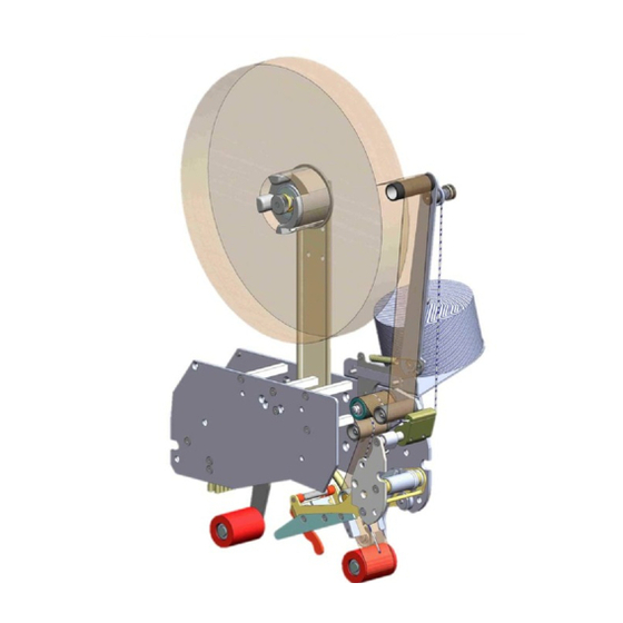
PECIFICATIONS Tape Head Components Smooth guide roller Tape Mandrel Peel-off arm Roll of tape Main spring Adhesive side of tape Smooth Rear arm guide roller Knurled clutch roller Smooth guide roller Knurled guide roller Link Front arm Wipe down brush Tape "shoe"... -
Page 10: Tape Head
PECIFICATIONS Operating Conditions Use in a dry, relatively clean environment at 40º to 105º F (5º to 40º C) with clean, dry cartons. Note: The HSD 2000-ET II Standard Tape Head should never be washed down or subjected to conditions causing condensation on components. HSD 2000-ET II SS Stainless Steel tape heads provide protection against mild detergent wash down only. -
Page 11: Machinery
Verify the case sizes which will be processed through the case sealer. Installing Interpack HSD 2000-ET II tape heads to process very short cases may cause the tape heads to collide with each other. -
Page 12: Set Up
ROCEDURES Receiving and Handling All contents must be verified upon reception. The following items are included with each tape head. UH 180TW UH 680TW UH 185TW UH 685TW ESCRIPTION 2” W 3” W 2” W 3” W LATED LATED TAINLESS TAINLESS Main Tape Head assembly SHCS M6 x 8 (part no. -
Page 13: Adapters
HSD 2000-ET II Tape Heads require Mounting Adapter Hardware to install in any case sealer or case erector. If your Tape Heads are pre-installed in your Interpack or TUFflex case sealer or case erector, you do not need to follow any instructions from this section. If your tape heads will be installed in any other competitive machinery, please review these general guidelines plus any additional instructions included with your HSD 2000-ET II tape head. -
Page 14: Tape Loading
ROCEDURES Tape Loading The HSD 2000-ET II Tape Heads accommodate 2-inch (48mm) wide tape rolls, while the HSD 2000-ET II/3" Tape Heads accommodate 3-inch (72mm) wide rolls. 1. Place the tape head onto a sturdy, flat surface. 2. Move the peel off roller away from the mandrel. 3. -
Page 15: Tape Threading
ROCEDURES ARNING HE KNIFE CONTAINED IN THE EAD IS EXTREMELY SHARP CAUTION WHEN REMOVING THE BLADE GUARD AND THREADING THE TAPE TO AVOID PERSONNEL INJURY Tape Threading Preparation Figure 7-5 Threading the tape in the Tape Head does not require any special tools. 1. - Page 16 ROCEDURES TAPE ROLL PEEL OFF ROLLER ADHESIVE SIDE GUIDE CLUTCH ROLLER ROLLER GUIDE ROLLER GUIDE ROLLER TAPE GUIDE SHOE Adhesive APPLICATION ROLLER Side Clutch Roller Guide Roller Figure 7-6 Figure 7-7 1. As illustrated in Figures 7-6 & 7-7, first thread the tape tail over the Peel Off Roller 2.
-
Page 17: Tape Centering
ROCEDURES Tape Centering If the tape is not centered as it travels through the tape shoe guide, the tape mandrel can be adjusted in or out to correct this Loosen the M18 inverse jam nut on the rear of the mandrel as shown in Figure 7-8 with a 10 mm allen key. -
Page 18: Tape Leg Length
ROCEDURES Tape Leg Length Adjustment For optimum performance, the tape leg length has been factory set at 2 inches (50 mm). However, the tape leg length can be modified. Front Tape Leg To adjust the tape leg length on the leading end of the box, refer to Figure 7-12 of the clutch assembly. -
Page 19: One Way Clutched Roller
ROCEDURES One Way Clutched Roller Adjustment This one direction, tensionable roller assures that proper tension is present when cutting the tape. It is preset at the factory but should re-adjustment be necessary, follow these steps: 1. Decrease all mandrel tension 2. -
Page 20: Mandrel Tension
ROCEDURES Mandrel Tension Adjustment Mandrel tension is required to control over spin of a full tape roll after the case is finished processing. The tension is set at the factory and no change to the tension should be necessary since the peel off roller should control the over spin in most cases. -
Page 21: Section 8 Troubleshooting
However, should a problem occur, we recommend that you consult the following table. If the problem you encounter is not discussed in this table, call Interpack Technical Support. (see page 2 of this document). ROUBLE... - Page 22 ROUBLESHOOTING ONTINUED ROUBLE OSSIBLE AUSES OLUTIONS “Tape Tabbing” or folding Generally, too much tension on itself on the trailing tape on the application of the tape. Follow steps below Applying urethane rollers, Remove any adhesive build up delrin guide rollers, knurled with silicon spray.
- Page 23 ROUBLESHOOTING ONTINUED ROUBLE OSSIBLE AUSES OLUTIONS Front tape leg too long Tape threaded incorrectly Check for proper tape threading against threading diagram on side plate of tape head Tape leg length misadjusted Re-set front tape leg length Rear tape leg too short Generally, too much tension Follow corrective action in “Tape on the application of the tape...
-
Page 24: Recommended Spare Parts
ECOMMENDED PARE ARTS We recommend that you stock the following spare parts. These parts are contained in the “spare parts kit” indicated below. The components of the spare parts kits are also referenced should individual components need to be ordered. HSD 2000-ET II Standard 2”... - Page 25 ECOMMENDED PARE ARTS HSD 2000-ET II SS Stainless Steel 2” Wide Spare Parts Kit UH 1004 Parts Contained in UH 1004 Spare Parts Kit ODEL UMBER ESCRIPTION UMBER UANTITY Roller shell ETM UPH0775 Ext. Spring, light UPH0910 Ext. main spring UPH1091 Knife guard spring UPH9195...
-
Page 26: Preventive
REVENTIVE AINTENANCE ARNING URN OFF ELECTRICAL POWER SUPPLY AND DISCONNECT THE POWER CORD FROM THE ELECTRICAL SUPPLY BEFORE BEGINNING TO WORK ON THE EADS OR TO LOAD TAPE POWER CORDS ARE NOT DISCONNECTED SEVERE INJURY TO PERSONNEL COULD RESULT The HSD 2000-ET II has been designed and manufactured with the finest components to provide long, trouble free performance. -
Page 27: Lubrication
REVENTIVE AINTENANCE Lubrication The HSD 2000-ET II tape heads ship from the factory permanently lubricated. No additional lubrication is necessary, however, a small amount of lightweight oil applied to rotating and pivot points will extend the life of the tape head and assure maximum performance. There is, however a felt pad on the blade guard which can serve as an oiler pad to help clean the blade should adhesive accumulate. -
Page 28: Replacement
REVENTIVE AINTENANCE Urethane Wipe Down Roller Replacement These red rollers are wear items and should be inspected regularly and replaced if necessary. Front & Rear Wipe Down Roller Replacement Removing The Urethane Roller 1. Using a snap ring pliers, remove the snap ring from the roller shaft. -
Page 29: Urethane Wipe Down Roller Spring Replacements
REVENTIVE AINTENANCE Spring Replacements There are 3 springs on the HSD 2000-ET II. These springs are wear items and should be inspected regularly and replaced if necessary. Below are instructions for replacing the two most common springs. Main Spring Replacement 1. - Page 30 REVENTIVE AINTENANCE Knife Guard Spring Replacement As a precaution, remove the cutter blade to avoid injury Figure 10-9 Remove the cross shaft NOTE: These screws are secured with loctite and may require applied heat prior to removal 1. Using two 2mm hexagonal keys as shown, remove one of the flathead countersink screws by applying force on both hexagonal key in an...
- Page 31 REVENTIVE AINTENANCE Carefully slide out the shaft from the end of the shaft that contains the remaining flathead countersink screw Figure 10-11 Remove the broken spring Figure 10-12 HSD 2000 ET II Mirror (UH181TW & UH681TW) UDH10014...
-
Page 32: Replacement
REVENTIVE AINTENANCE Behind The Cutter Blade To properly orient the new knife spring Position the new knife spring as shown in Figure 10-13. Note which leg of the spring should lie behind the cutter blade mounting plate Note which leg of the spring should wrap around the front of the knife guard In Front Of... -
Page 33: Maintenance
REVENTIVE AINTENANCE To Complete The Installation Apply some Blue Loctite to the threads of the M3 screw and fasten to the end of the cross shaft. Tighten using two 2mm hexagonal keys as shown in Figure 10-15 Rotate the knife guard to make sure there is no binding Re-install the cutter blade as shown in Figure 10-9... -
Page 34: Lists
REVENTIVE AINTENANCE Wipe Down Brush Replacement This multi row brush assists in wiping down the top center seam of the case. While the red wipe down rollers perform much of the wipe down, the wipe down brush enhances the wipe down as it can better conform to the irregularities of the top of the case such as over fills, void fills and the “wash-board”... - Page 35 CHEDULE F REVENTIVE AINTENANCE Frequency Item Action Required Material Weekly Monthly Quarterly Blade Guard Oiler Pad Lubricate Lightweight oil Re-tighten any loose hardware Hardware Replace any missing hardware Inspect for wear Cutter Blade Clean Solvent Cleaner Mandrel Assembly...
- Page 36 –I & PPENDIX LLUSTRATIONS ARTS ISTS Tape Head Sub-assemblies ..38 ...
- Page 38 This page is blank intentionally...
- Page 39 UH 211 / 711...
- Page 40 UH 211 / 711 UH211 - 2" mir. UH711 - 3" mir. ITEM PART # DESCRIPTION QTY. QTY. USH0829 MAIN FRAME ASS'Y MIRROR 72 USH0822 MAIN FRAME ASS'Y MIRROR 48 USH7017 FRONT COVER FRAME MIRROR USH7024 REAR COVER FRAME 75 MIRROR USH7023 REAR COVER FRAME 48 MIRROR USH7011...
- Page 41 USH 0822 / 0829...
- Page 42 USH 0822 / 0829 USH0822 - 2" mir. USH0829 - 2" mir. ITEM PART # DESCRIPTION QTY. QTY. UPH3755 MAIN ASS'Y FRAME MIRROR UPH3638 SPACER BAR ETM II - UPH9041 SPACER BAR ETM II - UPH3636 ARMS PIVOT SHAFT ETM II -...
- Page 43 USH 7017 & "...
- Page 44 USH 7017 627%8&%/9/:;<= ()*+ ,-.)/0 1*23.(,)(45 >)?= & 6,7@&8A B.45)/34C*./B.-+*/+(..4. & 6B#"8" B732/+#/9/8=A/D/&$/:: 6,78A%$ E5(B*/2,.(5F/.*)-(5*./*)+ & " 6,78A%% .*)-(5*./2G**C*H/E5(B*/-.+/2,.(5F & 6B$!8' .*)-(5(5F/.(5F/$++ & 6,7&!! 2)4,H/6.*)7-5*/E5(B*/-.+/ & 6,78A%' .*)-(5*.H/2)4,//*)+ &...
- Page 45 USH 7023 / 7024 " &...
- Page 46 USH 7023 / 7024 627%8'!/9/'I 627%8'"/9/!I ()*+ ,-.)/0 1*23.(,)(45 >)?= J>)?= & 6,7@&8" .*-./34C*./B.-+*/+(..4. & & 6B#"8" B732/+#/9/8=A/D/&$/:: 6,7!$## K.627/*)+/(( & 6,7!$%" K.627/*)+/(( & " 6,7!$"8 .*)-(5*.H/+-(5/2,.(5F//*)+/(( & " 6,7!$$$ .*)-(5*.H/+-(5/2,.(5F//*)+/(( & 6B$!8! *L)=/.*)-(5(5F/.(5F/@:: & & 6,78A$! +-(5/2,.(5F/.*)-(5*./2G**C* & & Note: The spring shown is for presentation purposes only, see page 39.
- Page 47 USH 7009/ 7010/ 7011/ 7012 " &! & &8 && " &'...
- Page 48 USH 7009 / 7010 / 7011/ 7012 627%88@/9/:;<='I 627%8&8/9/:;<='I22/ 627%8&&/9/:;<=!I 627%8&'/9/:;<=!I22 ()*+ ,-.)/0 1*23.(,)(45 >)?= >)?= >)?= >)?= & 6-788%$ +(..4./E5(B*/-.+/M=/K*-.(5F2/"A & & 6-788%@ +(..4./22/E5(B*/-.+/M=/K*-.(5F2/"A & & 6-788%% +(..4./E5(B*/-.+/M=/K*-.(5F2/%' & & 6-788%A +(..4./22/E5(B*/-.+/M=/K*-.(5F2/%# & 6,7@8!% E5(B*/26,,4.)/*)+/(( & & 6,7@8!@ E5(B*/26,,4.)/*)+/((/22 &...
- Page 49 UAH 0076/ 0077/ 0078/ 0079...
- Page 50 UAH 0076/ 0077/ 0078/ 0079 UAH0076 UAH0077 UAH0078 UAH0079 ITEM PART # DESCRIPTION QTY. QTY. QTY. QTY. UPH9188 KNIFE ARM MIR.48 UPH9190 KNIFE ARM MIR. 72 UPH9191 KNIFE ARM MIR. 72 SS UPH9189 KNIFE ARM MIR. 48 SS UPH0906 BEARING 10x12x10LG...
- Page 51 UAH 0088 / 0090...
- Page 52 UAH 0088/ 0090 UAH0088 UAH0089 UAH0090 UAH0091 ITEM PART # DESCRIPTION QTY. QTY. QTY. QTY. UPH 9184 BLADE PIVOT GUARD 48 MIRROR UPH 9186 BLADE PIVOT GUARD SS 48 MIRROR UPH 9185 BLADE PIVOT GUARD 72 MIRROR UPH 9187 BLADE PIVOT GUARD SS 72 MIRROR UPH9194 SLEEVE BUSHING 5mm ID, 8mm OD, 10LG UPI0067...
- Page 53 USH 3838/ 3839...
- Page 54 USH 3838/ 3839 USH3838 - 2" mir. USH3839 - 3" mir. ITEM PART # DESCRIPTION QTY. QTY. UAH0002 MIRROR FRONT ARM/BEARINGS UAH0074 GUIDE ROLLER W. BEARINGS 48 - UAH0075 GUIDE ROLLER W. BEARINGS 72 - UAH0013 MIR TAPE SHOE 48 -...
- Page 55 UAH 0002 / 0004...
- Page 56 UAH 0002 / 0004 UAH0002 UAH0004 - SS ITEM PART # DESCRIPTION QTY. QTY. UPH3711 MIRROR FRONT ARM ET II UPH3840 SS MIRROR FRONT ARM ET II UPH0907 BEARING 12 x 14 x 12 LG.
- Page 57 UAH 0013 / 0014 / 0015 / 0016 2 10 3 11...
- Page 58 UAH 0013 / 0014 / 0015 / 0016 UAH0013 - 2" UAH0013 - 2" UAH0014 - 3" UAH0014 - 3" UAH0015 - 2" SS UAH0015 - 2" SS UAH0016 - 3" SS UAH0016 - 3" SS ITEM ITEM PART# PART# DESCRIPTION DESCRIPTION QTY.
- Page 59 UAH 0074/ 0075...
- Page 60 UAH 0074/ 0075 UAH0074 - 2" UAH0075 - 3" ITEM PART # DESCRIPTION QTY. QTY. UPH0885 - UPH0969 - UPH0906 BEARING 10x12x10LG ...
- Page 61 USH 0931 / 0932 /0933 / 0934 10 18...
- Page 62 USH 0931 / 0932 /0933 / 0934 USH0931 - 2" mir. USH0932 - 3" mir. USH0933 - 2" SSmir. USH0934 - 3" SSmir. ITEM PART # DESCRIPTION QTY. QTY. QTY. QTY. UAH0018 MIRROR REAR ARM W. BEARING -...
- Page 63 UAH 0018 /0020...
- Page 64 UAH 0018 /0020 UAH0017 UAH0018 UAH0019 UAH0020 ITEM PART # DESCRIPTION QTY. QTY. QTY. QTY. UPH3713 MIRROR REAR ARM UPH3842 SS MIRROR REAR ARM UPH0907 BEARING 12 x 14 x 12 LG. UPH1034 SS BEARING 12 x 14 x 12 LG. UPH3841 SS REAR ARM UPH3645...
- Page 65 USH 0773...
- Page 66 USH 0773 USH0939 ITEM PART # DESCRIPTION QTY. UPH7100 LINK ET II UPH7101 ROD END BEARING, 10 mm R.H. UPH7102 ROD END BEARING, 10 mm L.H. UF1661 HEX JAM NUT M10-1.5 LEFT UF3708 HEX JAM NUT M10-1.5 UF6388 NYLON F.W. 10.5 x 16 x 0.85 mm UF6389 NYLON F.W.
- Page 67 USH 0927 / 0928...
- Page 68 USH 0927 / 0928 USH0927 - 2" mir. USH0928 - 3" mir. USH0929 - 2" SS mir. USH0930 - 3" SS mir. ITEM PART # DESCRIPTION QTY. QTY. QTY. QTY. UPH3715 CLUTCH BRACKET ET II MIR UPH0887 GUIDE ROLLER SHAFT -...
- Page 69 UAH 0029/ 0030...
- Page 70 UAH 0029/ 0030 UAH0029 - 2" UAH0030 - 3" ITEM PART # DESCRIPTION QTY. QTY. UPH0889 CLUTCH ROLLER UPH0951 CLUTCH ROLLER UPH0908 BEARING, ONE WAY, CLUTCH UPH0907 BEARING 12 x 14 x 12 LG.
- Page 71 USH 1008/ 1009/ 1010/ 1011...
- Page 72 USH 1008/ 1009/ 1010/ 1011 USH1008 - 2" USH1009 - 3" USH1010 - 2" SS USH1011 - 3" SS ITEM PART # DESCRIPTION QTY. QTY. QTY. QTY. UAH0093 MANDREL ARM SUB ASS'Y UAH0092 SS MANDREL ARM SUB ASS'Y UPH3762 SHAFT, MANDREL ETII TW 2" UPH3768 SHAFT, MANDREL ETII TW 3"...
- Page 74 UAH0093 UAH0092 ITEM PART # DESCRIPTION QTY. QTY. UPH3886 MANDREL ARM ET UPH3887 SS MANDREL ARM ET UPH9087 MANDREL HUB UPH3888 SS MANDREL HUB UF5404 FHCS M5 - 0.8 x 16 mm UF3277 SS FHCS M5 - 0.8 x 16 mm...
- Page 75 UAH 0072/ 0073...
- Page 76 UAH 0072/ 0073 UAH0072 - 2" UAH0073 - 3" ITEM PART # DESCRIPTION QTY. QTY. UPH3765 MANDREL 2" TW UPH3766 MANDREL 3" TW UPH3767 BEARING UPH1034 SS BEARING 12 x 14 x 12 LG.
- Page 77 USH 0935 / 0936 / 0937 / 0938...
- Page 78 USH 0768/ 0883/ 0884/ 0886 USH0935 - 2" mir. USH0937 - 3" mir. USH0938 - 2" SS mir. USH0936 - 3" SS mir. ITEM PART # DESCRIPTION QTY. QTY. QTY. QTY. UPH1291 PEEL-OFF ARM SUPPORT ET UPH3830 SS PEEL-OFF ARM SUPPORT ET UPH0904 PEEL-OFF ARM PIVOT UPH3827...
Need help?
Do you have a question about the HSD2000 ET II and is the answer not in the manual?
Questions and answers