
Related Manuals for Interpack CE-12P


Summary of Contents for Interpack CE-12P
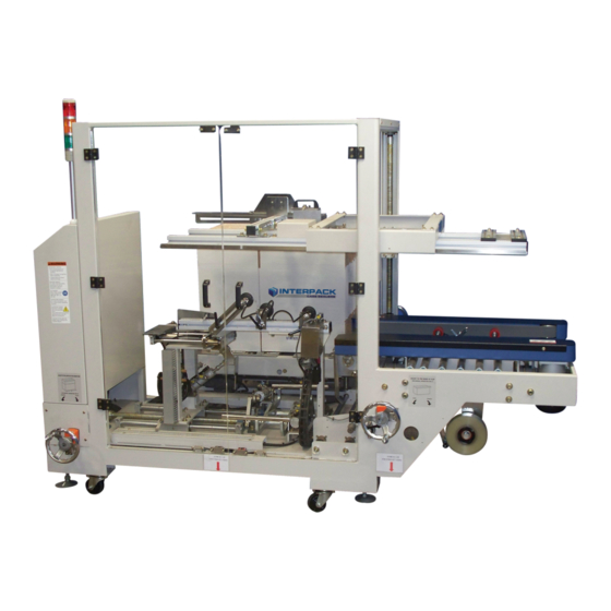
- Page 1 CE-12P Automatic Case Erector & Bottom Sealer OPERATION MANUAL & PARTS LIST This manual also available at www.itape.com. Rapid Packaging, Inc. 763-404-8900 | info@RapidPackaging.com www.RapidPackaging.com Page 1 of 36...
-
Page 2: Table Of Contents
TABLE OF CONTENTS GENERAL SAFETY RULES .................3 POWER SOURCE WIRING ..................3 CE-12P LAYOUT ....................4 MACHINE INSTALLATION ...................5 MANUAL FUNCTION LIST ...................6 FAULT LIST ......................6 OPERATION ......................7 ABNORMAL REMEDY ..................10 ELECTRIC CIRCUIT ...................12 AIR PRESSURE CIRCUIT ..................19 PNEUMATIC PART LIST ..................20 FRONT FLAP FOLDING ASSEMBLY ..............20... -
Page 3: General Safety Rules
GENERAL SAFETY RULES 1. Read and understand the entire instruction manual before operating the machine. Know it’s limitations, as well as the specific potential hazards peculiar to it. 2. Make certain the machine is properly grounded. 3. Before operating the machine, remove ties, rings, watches other jewelry, and roll up sleeves above the elbows. -
Page 4: Ce-12P Layout
CE-12P LAYOUT Page 4 of 36... -
Page 5: Machine Installation
MACHINE INSTALLATION 1. Please open the package and discharge the machine carefully for the installation. Please check if appearance is food without any damage, otherwise, please advise our company. 2. After installation, adjust the height of working table to parallel with the height of your production line. -
Page 6: Manual Function List
MANUAL FUNCTION LIST Description Side Belt On Vacuum Activated Vacuum Cup Forward Vacuum Cup Backward Guide Cylinder Front Minor Flap Folding Up Rear Minor Flap Folding Up Left Major Flap Folding Up Right Major Flap Folding Up Vacuum Released Pushing Cylinder FAULT LIST Description Low Air Pressure... -
Page 7: Operation
OPERATION 1. Please make sure correct power source 110V, turn on Magnetic Breaker. Connect air pressure at 5-6 kg/s.q.cm, switch on Manual Valve. 2. Adjust the location of Left//Right Belt (as Drawing 2) to fit the wide of cartons (as Drawing 1) 3. - Page 8 L&R Belt Upper working table adjusting wheel Drawing 2 Page 8 of 36...
- Page 9 Notice:The machine is suitable for various wide range size of carton, so Vacuum Cup and Stoppers are adjustable parts. If carton size is changed a lot for suitable position, all adjustment might be necessary. So step G and H are not necessary. 7.
-
Page 10: Abnormal Remedy
ABNORMAL REMEDY 1. Air Pressure is not enough,. Probable cause: a. The air is not connected to pressure source or no compression air. b. Air pressure is no enough. c. Manual valve is not open. 2. Not reset: Motion don’t return to home position, just press ”Manual Reset” 3. - Page 11 The vacuum cup can not draw the case on the folding line to prevent from the air leaking. a. After Up/Down stopper upward, the best distance is 2 mm between above angle R and carton. If stopper is over high, carton. If stopper is over high, carton will slip down or leap.
-
Page 12: Electric Circuit
ELECTRIC CIRCUIT Page 12 of 36... - Page 13 Page 13 of 36...
- Page 14 Page 14 of 36...
- Page 15 Page 15 of 36...
- Page 16 Page 16 of 36...
- Page 17 Page 17 of 36...
- Page 18 Page 18 of 36...
-
Page 19: Air Pressure Circuit
AIR PRESSURE CIRCUIT Page 19 of 36... -
Page 20: Pneumatic Part List
PNEUMATIC PART LIST N9310-700 Part No. Description Q’ty VM323-1 Vacuum pump AW3000-03D Air filter VHS400-03 Manual valve IS300-02 Pressure inspecting switch AL3000-03 Oil filter SS5Y5-20-04 Solenoid valve w/ base SS5Y5-20-03 Solenoid valve w/ base SY5320-5G-C8 Solenoid valve SY5120-5G-C8 Solenoid valve 117B-611BA Solenoid valve 101327601002... -
Page 21: Case Drawing Assembly
CASE DRAWING ASSEMBLY N9310-20A Part No. Description Q’ty N9310-201 Base frame M3303-A01B Case drawing cylinder stopper N9310-A02 Case drawing vacuum cup holder M3303-A12 Cylinder pushing base M3303-A05A Case drawing adjusting screw N9310-A14 Vacuum cup base M3303-A07A Case drawing wire bracket M3303-A09 Case inspecting base 81N-A020... - Page 22 Page 22 of 36...
-
Page 23: Left & Right Flap Folding Assembly
LEFT & RIGHT FLAP FOLDING ASSEMBLY N9310-20C Part No. Description Q’ty M3303-C01 Pushing arm M3303-C02 Flap folding rod (1) M3303-C03 Flap folding rod (2) M3303-C04 Flap folding arm Q1-251403 Washer 81-4010 Cylinder 81-4024 Cylinder base PHS14×1.5P Rod-eye bearing UCP204 Connecting bearing Page 23 of 36... -
Page 24: Rear Flap Folding Assembly
REAR FLAP FOLDING ASSEMBLY N9310-20D Part No. Description Q’ty M3303-D01 Case pushing bracket M3303-D02 Rear flap folder M3303-D03 Case pushing guide screw M3303-D04 Case pushing cylinder base M3303-D05 Case outlet pushing plate M3303-D06 Case pushing assisting plate M3303-D07 Shaft bracket M3303-D08 Pusher shaft 818-2062... - Page 25 Part No. Description Q’ty Q1-201204 Washer SF16×315L Linear shaft SF25×575L Linear shaft SH25A Shaft bracket SH16A Shaft bracket UCP203 Connecting bearing HO-6” Hand wheel C-R32 C circlet HJ 45B M6×25 B Handle 45B M6×25 Indicating finger Page 25 of 36...
-
Page 26: Safety Door Assembly
SAFETY DOOR ASSEMBLY N9310-20E Part No. Description Q’ty M3303-E01 Door M3303-E06 Control box cover L6303-E06 Magnet plate L6303-E11 Top magnet base L6303-E12 Bottom magnet base HAND-14121 Handle FDM0640-8A Magnet FHI0645-B Hinge Page 26 of 36... -
Page 27: Hopper Base
HOPPER BASE N9310-100A Part No. Description Q’ty M3303-114 Base frame M3303-102 Driving shaft M3303-103 Nut (L&R) M3303-104 Driven shaft M1321-135 Elevating fix plate M3303-106 Elevating collar M3303-107 Elevating screw (L&R) M1321-138 Elevating unit M3303-109 Table bracket N9310-110 Limit fix rod M3303-111 Gear (1) M3303-112... - Page 28 Page 28 of 36...
-
Page 29: Hopper Top Unit
HOPPER TOP UNIT N9310-100B Part No. Description Q’ty M3303-161 Hopper top unit M3303-162 Hopper table (1) M3303-143 Hopper table (2) M3303-144 Hopper table (3) M3303-145 Hopper table (4) M3303-146 Driven shaft M3303-147 Driving shaft M3303-148 Case pushing base M3303-149 Chain guide rail M3303-150 Chain guard M3303-151... - Page 30 Part No. Description Q’ty Handle LMF25LUU Flanged linear bearing M10×90L Hex. socket screw RS141018 Chain sprocket RS141315A Chain sprocket RS141325 Chain sprocket RS14150E Chain sprocket RS141525A Chain sprocket SF25×1442L Linear shaft A72-1370 Limit switch UFL005 Connecting bearing RS40×43 Chain RS40×222 Chain 843-K144 Chain...
-
Page 31: Bottom Sealing Assembly
BOTTOM SEALING ASSEMBLY N9310-300 Part No. Description Q’ty N9310-302 Tape head holding unit (L&R) N9310-305A Tape head cover (2”) 818-2062 Lock block, adjusting rod 81N-3070 Driving shaft 81N-3100 Spring driving plate 81N-3110 Spring fix plate 81N-3130 Spring fixer 81N-3170 Chain moving base (FR) 81N-3180 Spring 81N-326C... - Page 32 Part No. Description Q’ty ROL-0109 Roller ROL-0321 Roller ROL-0774 Roller ROS-0124 Roller shaft ROS-0338 Roller shaft ROS-0789 Roller shaft E00-1200 Plastic bush E00-2080 Motor RS141120 Chain sprocket RS141317 Chain sprocket RS40×28 Chain RS40×57 Chain RS40 SF20×845L Linear shaft U73-2070 Hex. screw U73-2080 Die spring UCPA204...
- Page 33 Page 33 of 36...
-
Page 34: Top Unit Adjusting Assembly
TOP UNIT ADJUSTING ASSEMBLY N9310-400 Part No. Description Q’ty N9310-401 Active elevating guide rod N9310-402 Elevating guide rod N9310-403 Top unit side plate (L&R) N9310-404 Top table N9310-406 Top beam (L&R) N9310-411 Top stopping base 81N-3241 Lock block, adjusting rod 81N-4080 Bracket 81N-4090... - Page 35 Part No. Description Q’ty HJ-45B-M6-25-B Handle HJ-63B-M8-20-B Handle SB-1200 Balancer UFL003 Connecting bearing HO-6” Handle RS35×176 Chain N9310-412 Top unit adjusting plate M3303-410 Weight balance block 15*60*330L Weight balance compressing plate 2 Page 35 of 36...
-
Page 36: Electric Control Box
ELECTRIC CONTROL BOX N9310-600 Part No. Description Q’ty M3303-601 Electric control box 81NFA-602 Electric control box cover 81NFA-603 Wiring plate M3303-604 Electric control box name plate Page 36 of 36...
Need help?
Do you have a question about the CE-12P and is the answer not in the manual?
Questions and answers