
Subscribe to Our Youtube Channel
Related Manuals for Interpack USA 2024-SB


Summary of Contents for Interpack USA 2024-SB
- Page 1 USER MANUAL USA 2024-SB USA 2024-SB UNIFORM SEMI-AUTOMATIC CASE SEALER For Serial Numbers: TM094 or TM594 XX X XXX Serial Numbers TM094 or TM594 XX X XXX...
-
Page 2: Table Of Contents
Section 2 Revision Control--------------------------------------------------- 3 Section 2 Technical and Field Assistance------------------------------ 4-5 Section 3 Warranty-------------------------------------------------------------- 6 Section 4 Description of the USA 2024-SB Case Sealer----------- 7 Section 5 Important Safeguards-------------------------------------------- 8-15 Section 6 Specifications------------------------------------------------------- 16-20 Section 7 Set-Up Procedures------------------------------------------------ 21-34... -
Page 3: Section 2 Revision Control
EVISION ONTROL REVISION CONTROL REV00 Initial Release Modified Index REV01 REV02 Final Release REV03 Updated Updated REV04 REV05 Updated UM094TW / UM594TW UDM094-04... -
Page 4: Section 2 Technical And Field Assistance
SSISTANCE Technical Support This is the Interpack Model USA 2024-SB Uniform Semi-Automatic Case Sealer you ordered. It has been set up and tested in our factory with Intertape manufactured pressure sensitive tapes. If any problems occur when setting up or operating this equipment, please contact the authorized distributor from where you purchased this item. - Page 5 Trouble Shooting section of this manual. However, after consulting the Trouble Shooting Section of this manual, you cannot remedy the problem, customer paid service support is available from your Authorized Interpack Distributor. UM094TW / UM594TW UDM094-04...
-
Page 6: Section 3 Warranty
Intertape sells its Interpack Tape Heads, Case Tapers and Case Erectors with the following warranties: ... -
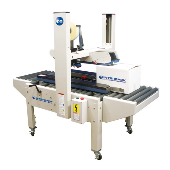
Page 7: Section 4 Description Of The Usa 2024-Sb Case Sealer
Intertape brand pressure sensitive carton sealing tape to the top and bottom center seam of regular slotted corrugated cartons. The USA 2024-SB is manually adjustable to a wide range of carton sizes (see Carton Size Capacity, page 20). Multi-Wheel Top Squeezers compress the top major flaps ensuring superior seal. -
Page 8: Section 5 Important Safeguards
Important Safeguards There are a number of safety labels used on Interpack Carton Sealers. These labels are placed at different locations (refer to Figure 2) on the machine to warn operators and service personnel of possible dangers. Please read the labels on the machine and the following safety precautions before using the machine. - Page 9 Important Safeguards Figure 2 UM094TW / UM594TW UDM094-04...
- Page 10 Important Safeguards There Are A Number Of Safety Labels Used On Intertape Carton Sealers. The illustrated label as shown is attached to the Knife Guard inside the upper and lower HSD2000 ET II Tape Head. The label warns operators and service personnel of the very sharp knife used to cut the tape at the end of the tape application.
- Page 11 Important Safeguards The label shown is affixed to the top squeezer assembly brackets on either side of the machine. They warn the operator of a potential pinch point between the top of the case and the top squeezer rollers. Keep hand away from this area when processing a case This label affixed to the electrical control box advises service personnel to connect...
- Page 12 Important Safeguards The illustrated label shown is located on the side of the column. This label provides convenient safety instructions for the operator and service personnel in the operation of the Intertape Carton Sealing Equipment. Note: Should Any Of The Safety Labels Placed On The Machine Be Damaged Or Destroyed, Replacements Are Available.
- Page 13 Important Safeguards Explanation of Signal Word Consequences Warning: Indicates A Potentially Hazardous Situation, Which If Not Avoided Could Result In Death Or Serious Injury Or Property Damage Caution: Indicates A Potentially Hazardous Situation, Which If Not Avoided Could Result In Minor Or Moderate Injury Or Property Damage Warning ...
- Page 14 Important Safeguards Warning To Reduce The Risk Associated With Mechanical And Electrical Hazards: a. Allow Only Properly Trained And Qualified Personnel To Operate And Service This Equipment. Operator Skill Level Descriptions Skill “A”: Machine Operator This Operator Is Trained To Use The Machine With The Machine Controls, To Feed Cases Into The Machine, Make Adjustment For Different Case Sizes, To Change The Tape And To Start, Stop, And To Re-Start Production Important: The Area Supervisor Must Ensure That The Operator...
- Page 15 Important Safeguards Operators Skill Level Required To Perform The Following Tasks On The Machine Operator Skill Number Of Operation Machine Condition Level Operators Running With Safety Protections Machine Installation & Set Up B & C Disabled Stopped By Pressing The Adjusting Case Size Emergency Stop Button Stopped By Pressing The...
-
Page 16: Section 6 Specifications
PECIFICATIONS USA 2024-SB Machine Dimensions Figure-3 Machine Weight: 560 lbs. (254 kg) crated UM094TW / UM594TW UDM094-04... - Page 17 PECIFICATIONS USA 2024-SB Machine Components Tape Head See Section 7, Page 31 In This Manual For Tape Loading & Threading. Case Width Adjustment Top Squeezer Conveyer Height Adjustment Control Box Figure-4 UM094TW / UM594TW UDM094-04...
- Page 18 PECIFICATIONS 1. Operating Conditions Use in a dry, relatively clean environment at 40° to 105° F (5° to 40° C) with clean dry cartons. Note: Machine should not be washed down or subjected to conditions causing condensation on components. 2. Power Requirements Electrical - 115 VAC, 60 HZ, 5.0 A (560 Watts) Compressed Air –...
- Page 19 4. Tape Specifications Use Intertape Brand Pressure Sensitive Carton Sealing Tape. The machine can accommodate 2” (48mm) or 3” (72mm) wide tape, depending on tape heads supplied. A maximum tape roll diameter of 16” (406 mm) on a 3” (76 mm) diameter core can be installed on the tape head.
- Page 20 5. Carton Specifications Type Regular Slotted Containers (RSC) Other Style Cases May Be Processed. Consult Factory For Details. Material 125 To 275 PSI Bursting Test, Single Or Double Wall B Or C Flutes. Weight 0 to 85 lbs. (0 to 38.6 kg) Size ...
-
Page 21: Section 7 Set-Up Procedures
Figure-6 All contents must be verified upon reception. The following items are included with each machine. USA 2024-SB Operators Manual Machine Operators Manual Tape Head Plastic bag containing tape head spare parts. Note: After Unpacking The Case Sealer, Look For Any Damage That May Have Occurred During Shipping. - Page 22 ROCEDURES 2. Caster Installation (If Purchased) Caster Installation Requires Raising The Machine To Access The Bottom Of Each Leg. Please Follow All Possible Safety Procedures Prior To And During This Process A. With A Fork Lift, Raise The Machine To Allow Access To The Bottom Of Each B.
- Page 23 ROCEDURES 3. Machine Height Adjustment Machine Height Adjustment Requires Raising The Machine To Adjust Each Leg. Please Follow All Possible Safety Procedures Prior To And During This Process The Carton Sealer must be installed on near level ground. Use the adjustable legs to ensure that the machine is level and firmly on the ground (no rocking).
- Page 24 ROCEDURES 4. Installation of Interpack Brand In-Feed and Exit Roller Tables (If Purchased) Case Direction Figure-9 a. Install Four (4) Mounting Studs Into Machine Base With Hardware Included With Figure-9 Roller Table. Per b. Utilizing The Slots In The Roller Table, Attach Roller Table To Machine Base By Locating Mounting Studs In Slots On Roller Table And Push Down To Lock In Place.
- Page 25 ROCEDURES 5. Installation of External In-Feed and Exit Conveyors Exit Conveyor In-Feed Conveyor Figure-10 1. Customer supplied in-feed conveyor (if used) should provide straight and level entry into the case sealer. 2. Customer supplied gravity exit conveyor (if used) should be straight and declined no more than 20mm/meter away from the machine to convey the sealed cartons away from the machine.
- Page 26 ROCEDURES 6. Machine Final Assembly The machine is shipped with all adjustment handles installed. Location of Adjustment Handles. Figure-11 UM094TW / UM594TW UDM094-04...
- Page 27 ROCEDURES 7. Connecting Utilities Electrical Start E-Stop Figure-12 An eleven foot (11’) standard three conductor power cord with plug is provided for 115 V, 60 Hz, 15 amp electrical service. The receptacle must be properly grounded. Before the machine is plugged into the receptacle, ensure that all materials are removed from the machine.
- Page 28 ROCEDURES 8. Relocating Operator Controls This case sealer is shipped with the operator controls mounted on the left hand side of the machine (when viewed from the in feed of the machine). Certain machines have the ability to relocate the operator controls to the opposite side. Figure-13 Re-Locating Adjustment Handles.
- Page 29 ROCEDURES Re-Locating Electrical Control Box Start E-Stop Figure-15 Moving the control box to the opposite side of the machine requires disconnecting and reconnecting electrical wires and components. Only trained and qualified service technicians should access an open control box. Please Follow All Possible Safety Procedures Prior To And During This Process a.
- Page 30 ROCEDURES 9. Removing Tape Heads Prior to Tape Loading Removing Upper Tape Head Figure-16 1. Slide Tape Head Toward The Infeed End Of Machine And Rotate Up. 2. Slide Tape Head Toward The Exit End Of Machine And Lift Out Of Rear Slot. Removing Lower Tape Head Top Tape Head Box Assembly Removed For...
- Page 31 ROCEDURES 10. Tape Loading The HSD 2000-ET II Tape Heads accommodate 2-inch (48mm) wide tape rolls, while the HSD 2000-ET II/3" Tape Heads accommodate 3-inch (72mm) wide rolls. 1. Place the tape head onto a sturdy, flat surface. 2. Move the peel off roller away from the mandrel. 3.
- Page 32 ROCEDURES ARNING HE KNIFE CONTAINED IN THE EAD IS EXTREMELY SHARP SE CAUTION WHEN THREADING THE TAPE TO AVOID PERSONAL INJURY 11. Tape Threading Preparation Figure-19 Threading the tape in the Tape Head does not require any special tools. Pull approximately twelve (12) inches of tape from the roll and fold in half lengthwise, adhesive side to adhesive side.
- Page 33 ROCEDURES 12. Tape Threading TAPE ROLL PEEL OFF ROLLER ADHESIVE SIDE GUIDE CLUTCH ROLLER ROLLER GUIDE ROLLER GUIDE ROLLER TAPE GUIDE SHOE APPLICATION Clutch Roller ROLLER Adhesive Side Knurled Guide Guide Roller Roller Guide Roller Figure-20 Figure-21 Figure-20 1. As Illustrated In , First Thread The Tape Tail Over The Peel Off Roller.
- Page 34 ROCEDURES 13. Re-Installing Tape Heads Figure-22 1. Insert Exit End of Tape Head into Rear Slots. 2. Rotate Front of Tape Head Down Into Front Slots 3. Push Front of Tape Head Down to Seat in Bottom of Slot. UM094TW / UM594TW UDM094-04...
-
Page 35: Section 8 Operating Instructions
PERATING NSTRUCTIONS Case Size Set Up Functions Figure-23 UM094TW / UM594TW UDM094-04... - Page 36 1. Initial Condition Figure-24 Figure-25 Figure-26 Figure-24 a. Raise the upper head as shown in Figure-25 b. Open Side Drives or Centering Guides as shown in Figure-26 c. Loosen Each Locking Knob And Open Top Squeezers as shown in UM094TW / UM594TW UDM094-04...
- Page 37 2. Preparation Of Case To Be Processed Figure-27 Figure-28 a. Flap Folding Figure-27 i. Fold Minor Flaps In As Shown In Figure-28 ii. Fold Major Flaps In As Shown In Figure-29 Figure-30 b. Over Fills And Void Fills. Figure-29 Figure-30 Over Fills As Shown In And Void Fills As Shown In Should Be Avoided To Assure Proper Processing Of The Corrugated Case.
- Page 38 3. Case Width Adjustment Turn Case Width Handle As Shown in Figure-31 Until Side Drive Belts Contact Case. Side Drive Belts Should Contact The Case Firmly Enough So Case Processes Smoothly But Not So Firm As To Score The Side Of The Case.
- Page 39 5. Top Squeezer Adjustment Slide Each Top Squeezer To Contact The Case Firmly Figure-34 And Tighten Each Locking Knob As Shown In Each Top Squeezer Should Be Firm Enough On The Case To Completely Close Any Gap On The Center Seam But Not So Firm As To Restrict The Smooth Processing Of The Case Figure-34 6.
- Page 40 7. Review Of Case Processing Case Should Process Smoothly Through The Machine And Apply The Tape Evenly To Each Top And Bottom Major Flap With A 2 ¼” Tape Leg Applied To Each End Panel. Should The Case Processing Need Correction Please Refer To The Trouble Shooting Section In This Manual UM094TW / UM594TW UDM094-04...
- Page 41 However, should a problem occur, we recommend that you consult the following table. If the problem you encounter is not discussed in this table, call Interpack Technical Support (see page 2 of this document).
-
Page 42: Section 8 Troubleshooting
ROUBLESHOOTING ONTINUED Trouble Possible Causes Solutions Case Processes But Product Does Not Support The End Insert Proper Dunnage Material Leading End Panel Is Panel Of The Case To Provide Support Crushed Main Spring Tension On Tape Head Reduce Main Spring Tension. Too Strong See Tape Head Manual Provided With Tape Head... - Page 43 ROUBLESHOOTING ONTINUED Trouble Possible Causes Solutions Rear Tape Leg Is Tape Threaded Incorrectly Review Tape Threading Page 33 Folded Or Wrinkled Adhesive Build Up In Tape Path Clean Tape Guide Rollers To Provide A Free Rotation Clean Tape Path, Blade Dull Blade Replace Blade Excessive Unwind Tension From...
-
Page 44: Section 9 Recommended Spare Parts List
Trouble Shooting section of this manual. However, after consulting the Trouble Shooting Section of this manual, you cannot remedy the problem, customer paid service support is available from your Authorized Interpack Distributor. UM094TW / UM594TW UDM094-04... - Page 45 REVENTATIVE AINTENANCE The USA 2024-SB has been designed and manufactured with the finest components to provide long, trouble free performance. General preventive maintenance will improve performance and prolong the life of the case sealer Please review the illustrations and chart below for information regarding machine And Tape...
- Page 46 REVENTIVE AINTENANCE Tape Head Preventative Maintenance Chart Frequency Item Action Required Material Weekly Monthly Quarterly Blade Guard Oiler Pad Lubricate Lightweight oil Re-tighten any loose hardware Hardware Replace any missing hardware Inspect for wear Cutter Blade Clean Solvent Cleaner Disassemble & Observe Mandrel Assembly Mandrel Spring Check for weakness None...
-
Page 47: Section 10 Preventive Maintenance
REVENTIVE AINTENANCE Cleaning The Machine Side Belt Drive Base Column Shaft Connecting Chain Figure-36 Warning! Please Exercise All Safety Precautions Prior To Starting This Procedure. Disconnect Electrical Power And Wear Approved Safety Glasses a. Side Belt Drive Base Insert An Air Nozzle Along The Top Edge Of The Belt Into The Opening Of The Drive Base And Clean Out Any Dust And Dirt b. - Page 48 REVENTIVE AINTENANCE Lubricating the Machine Column Shaft Centering Chain Acme Drive Base Shaft Figure-37 a. Column Shaft. Lubricate Both Shafts With Industrial Grade Silicone. b. Acme Drive Base Shafts. Lubricate Both Shafts With Light Machine Grease. c. Centering Chain. Lubricate Chain With Chain Lubricant. UM094TW / UM594TW UDM094-04...
-
Page 49: Section 11 Machine Maintenance & Adjustment
& A ACHINE AINTENANCE DJUSTMENT Drive Belt Replacement Using a 4mm Allen key, remove screws (2) and remove drive base cover. Using appropriate Allen key and wrench, loosen belt tensioning bolts. Remove worn belt and replace with new belt. Using appropriate Allen key and wrench, tighten belt tensioning bolts. - Page 50 & A ACHINE AINTENANCE DJUSTMENT Intertape S/B drive idler pulleys are engineered to self-track to center. After tensioning, if the belts do not track on center, contact maintenance or your IPG Distributor. Using a 4mm Allen key, replace drive base cover as shown.
- Page 51 & A ACHINE AINTENANCE DJUSTMENT Drive Belt Adjustment Using a 4mm Allen key, remove screws (2) and remove drive base cover. Using appropriate Allen key and wrench , tighten belt tensioning bolts. Be sure to adjust upper and lower tensioning bolts equally.
-
Page 52: Section 12 Optional Equipment
PTIONAL QUIPMENT 3” Tape Head 2” Tape Head 3 Flap Folders Exit Table In Feed Table In Feed Table With Hold Down Device Castors UM094TW / UM594TW UDM094-04... -
Page 53: Section 13 Schematic Diagrams
CHEMATIC IAGRAMS Electrical Drawing UM094TW / UM594TW UDM094-04... -
Page 54: Section 14 Appendix A-Illustrations And Parts Lists
ELECTRICAL ASSEMBLY (illustration)..............A-13 ELECTRICAL ASSEMBLY (parts list)...............A-14 ELECTRIC BOX (illustration)..................A-15 ELECTRIC BOX (parts list)..................A-16 COLUMN LEFT (illustration)..................A-17 COLUMN LEFT (parts list)..................A-18 COLUMN RIGHT (illustration)..................A-19 COLUMN RIGHT (parts list)..................A-20 BRIDGE WITH TAPEHEAD BOX (illustration)............A-21 BRIDGE WITH TAPEHEAD BOX (parts list).............A-22 USA 2024-SB METRIC... - Page 55 DRIVE BASE ASSEMBLY LEFT (parts list)..............A-34 DRIVE BASE ASSEMBLY RIGHT (illustration)............A-35 DRIVE BASE ASSEMBLY RIGHT (parts list)............A-36 SECOND E-STOP ASSEMBLY (illustration) ............A-37 SECOND E-STOP ASSEMBLY (parts list)..............A-38 SECOND E-STOP BOX (illustration) .................A-39 SECOND E-STOP BOX (parts list)................A-40 ELECTRICAL DRAWING ..................A-41 USA 2024-SB METRIC...
- Page 56 UM094TW UM594TW USA 2024-SB METRIC...
- Page 57 SINGLE LOCK.ASS'Y UPM3227 PVC ROL CHARCOAL DIA 1.9 X 4.50 UPM3226 PVC ROL CHARCOAL DIA 1.9 X 12.00 USM0812 DRIVE BASE ASSY LH USM0811 DRIVE BASE ASS'Y RH USM6116 BRIDGE WITH TAPEHEAD BOX UAM0260 COMPRESSION GUIDE USA2324 BB USA 2024-SB METRIC...
- Page 58 USM6115 USA 2024-SB METRIC...
- Page 59 USM6115 ITEM PART # DESCRIPTION QTY. UAM0328 BASE SUB-ASS'Y UAM0275 LEG ASSEMBLY METRIC USM6111 DRIVE CENTRING ASS'Y USM0817 ELECTRICAL ASSEMBLY USA 2024-SB METRIC...
- Page 60 UAM0328 10 13 USA 2024-SB METRIC...
- Page 61 UF5402 FHCS M6 - 1 x 20 UF6411 SS LW M6 UF3179 SS SHCS M6-1 X 20mm UF4229 CARRIAGE BOLT M10-1.5 x 20 UF3680 FW M10 UF6371 L.W. M10 UF6314 HNR M10 x 1.5 UPM3229 INLET COVER USA 2024-SB METRIC...
- Page 62 UAM0275 USA 2024-SB METRIC...
- Page 63 LEG ADJ USTMENT UPM7642 LEG FRICTION PLATE UF4230 L.W. ZINC M12 UF6393 HHCS M12-1.75 x 35 UF3680 FW M10 UF6371 L.W. M10 UF6314 HNR M10 x 1.5 UF4229 CARRIAGE BOLT M10-1.5 x 20 UF4231 FW M12 A-10 USA 2024-SB METRIC...
- Page 64 USM6111 A-11 USA 2024-SB METRIC...
- Page 65 FLANGE BEARING UF0866 HNR M8-1.25 UF0867 LW M8 UPM0631EV TENSIONNER BRACKET UPM0640EV TENSIONNER PIN UPM0641 CHAIN TENSIONNER SPACER UF5402 FHCS M6 - 1 x 20 UPM0639EV SLEEVE BEARING 12 mmID 3/4OD 3/4LG UF2170 1/2" RETAINING RING A-12 USA 2024-SB METRIC...
- Page 66 USM0817 A-13 USA 2024-SB METRIC...
- Page 67 ITEM PART # DESCRIPTION QTY. UAM0264 ELECTRIC BOX ASSEMBLY UPM0197EV STR.RELF METL.LIQDTGHT M20X1.5 (8-10mm) 4 UPM0341EV LOCKNUT M20 X 1.5(FOR STRAIN RELF) UPM0209 POWER CORD, 14/3 UPM0225 CABLE 18/3 TYPE SJ UF3646 SHCS M4-0.7 x 20 A-14 USA 2024-SB METRIC...
- Page 68 UAM0264 A-15 USA 2024-SB METRIC...
- Page 69 DIN RAIL USA 2324 UPM7440EV TB END ANCHOR FOR DN SER UPM2209EV LEGEND PLATE "E-STOP" UPM2210EV LEGEND PLATE "START" UPM7524 MOTOR STARTER TELEMEC 110VAC UPM2213EV MOTOR O/L TELEMEC 2.5-4.0A UF3710 FW M4 UF6365 BHCS M4 x 0.7 x 10mm A-16 USA 2024-SB METRIC...
- Page 70 USM0807 A-17 USA 2024-SB METRIC...
- Page 71 UPM4210 SPRING MANDREL SHAFT UPM0742 SPRING SPOOL UPM2181 CONSTANT FORCE SPRING UPM9651 COLUMN BLOCK 40 mm BORE LM 25UU LINEAR BEARING 25 mm UF3278 SS BHCS M6-1 x 12 mm UF0457 HHCS M10-1.25 x 20 mm A-18 USA 2024-SB METRIC...
- Page 72 USM0806 A-19 USA 2024-SB METRIC...
- Page 73 UPM0742 SPRING SPOOL UPM0740 CONSTANT FORCE SPRING UPM2181 CONSTANT FORCE SPRING UPM9651 COLUMN BLOCK 40 mm BORE LM 25UU LINEAR BEARING 25 mm UF3278 SS BHCS M6-1 x 12 mm UF0457 HHCS M10-1.25 x 20 mm A-20 USA 2024-SB METRIC...
- Page 74 USM6116 A-21 USA 2024-SB METRIC...
- Page 75 USM6116 ITEM PART # DESCRIPTION QTY. UAM0326 BRIDGE SUB-ASSEMBLY UAM0296 PIVOT ASS'Y UAM0297 PIVOT ASS'Y UAM0325 TAPEHEAD BOX USA 3036 SB A-22 USA 2024-SB METRIC...
- Page 76 UAM0326 A-23 USA 2024-SB METRIC...
- Page 77 UF6365 BHCS M4 x 0.7 x 10mm UF1241EV BHCS M6-1 x 20 UPM2284EV FRONT COVER UF5900 NYLON LOCK NUT M6-1.0 UPH133 STOP, KNIFE ARM, 15/16"D.URETH. UF3680 FW M10 UF6371 L.W. M10 UF6384 BHCS M10-1.5 x 40 A-24 USA 2024-SB METRIC...
- Page 78 UAM0325 A-25 USA 2024-SB METRIC...
- Page 79 UPM3246 ET T.H. TOP GAP FILLER UF7008 SS BHCS M4-07 X 6mm UPM0029 STRIP, UHMW, 2" W X .03" THK UF2080 POP RIVET S-44 UF6374 BHCS M4-0.7 x 6 mm UPM2192 BLACK PLUG UF3681 L.W. M4 A-26 USA 2024-SB METRIC...
- Page 80 UAM0296 UAM0297 A-27 USA 2024-SB METRIC...
- Page 81 RETAINING RING FOR 12mm SHAFT UF1241EV BHCS M6-1 x 20 UF1192 FHCS M6-1 x 16 mm UPM1158 PIVOT SHAFT SPACER UF1940 F.W. NYLON 1/2IDx.772ODx.032TH UPM2247EV PIVOT SHAFT SHORT T.H. BOX 222 UPM0962EV SPRING RETAINER UF3646 SHCS M4-0.7 x 20 A-28 USA 2024-SB METRIC...
- Page 82 USM0391 A-29 USA 2024-SB METRIC...
- Page 83 UPM2866 SS SINGLE LOCKING BLOCK UPM0698 FLANGED SCREW 1/2-13 L.H. UPM0699 FLANGED SCREW 1/2-13 R.H. UPM0703 SHORT BOX 3/4", 1/2" DR, 12 PT UPM0688 SINGLE LOCKING HANDLE UPM2184 COMPRESSION SPRING, UF1318 BHCS M8-1.25 x 20 mm A-30 USA 2024-SB METRIC...
- Page 84 UAM0260 A-31 USA 2024-SB METRIC...
- Page 85 PART # DESCRIPTION QTY. UPM7491 WHEEL SUPPORT PLATE UPM3285EV GUIDE BLOCK UPM7538EV GUIDE BLOCK TOP UAM0288 KNOB CW 5mm PIN USA2324 UPM1659 WHEEL 2-7/8"DIA.COMPR.GUIDE UF0240 HHCS 3/8-16 x 1.75 UF6373 FHCS M6 - 1 x 55 A-32 USA 2024-SB METRIC...
- Page 86 USM0812 10 11 4 19 28 27 A-33 USA 2024-SB METRIC...
- Page 87 UF1194 FHCS M6 - 1 x 25 mm UF2080 POP RIVET S-44 UF5402 FHCS M6 - 1 x 20 UF1610 HNJ 3/8-16 UF6363 LW M6 UF0454 M6-1.0 X 16mm HHCS UF1195 BHCS M6-1 x 12 mm A-34 USA 2024-SB METRIC...
- Page 88 USM0811 11 18 A-35 USA 2024-SB METRIC...
- Page 89 UF3711 BHCS M6-1 x 30 UF1194 FHCS M6 - 1 x 25 mm UF0454 M6-1.0 X 16mm HHCS UF1400 SSS HK 3/8-16 X 3 UF1610 HNJ 3/8-16 UF6363 LW M6 UF1195 BHCS M6-1 x 12 mm A-36 USA 2024-SB METRIC...
- Page 90 UM9003 A-37 USA 2024-SB METRIC...
- Page 91 UM9003 ITEM PART # DESCRIPTION QTY. USM8075 SECOND E-STOP BOX FOR USA UPM0225 CABLE 18/3 TYPE SJ UPM0341 LOCKNUT 1/2"(FOR STRAIN RELF) UPM0197 STR.RELF METL.LIQDTGHT 1/4-3/8 UPM0200 MTG. CLAMP,ADH.1.2"X1.2" UPM0222 TY-RAP,5.5"X.14" UPM0285 STRAIN RELIEF, NON-METAL A-38 USA 2024-SB METRIC...
- Page 92 USM8075 A-39 USA 2024-SB METRIC...
- Page 93 USM8075 ITEM PART # DESCRIPTION QTY. UPM7293 ENCLOS PB 1 HOLE NON METAL UPM2211 BUTTON MUSHROOM 22mm 1 N.C. UPM2209 LEGEND PLATE "E-STOP" UPM0341 LOCKNUT 1/2"(FOR STRAIN RELF) UPM0197 STR.RELF METL.LIQDTGHT 1/4-3/8 A-40 USA 2024-SB METRIC...
- Page 94 Electrical Drawing A-41 USA 2024-SB METRIC...
Need help?
Do you have a question about the USA 2024-SB and is the answer not in the manual?
Questions and answers