
Related Manuals for Interpack CE-12P


Summary of Contents for Interpack CE-12P
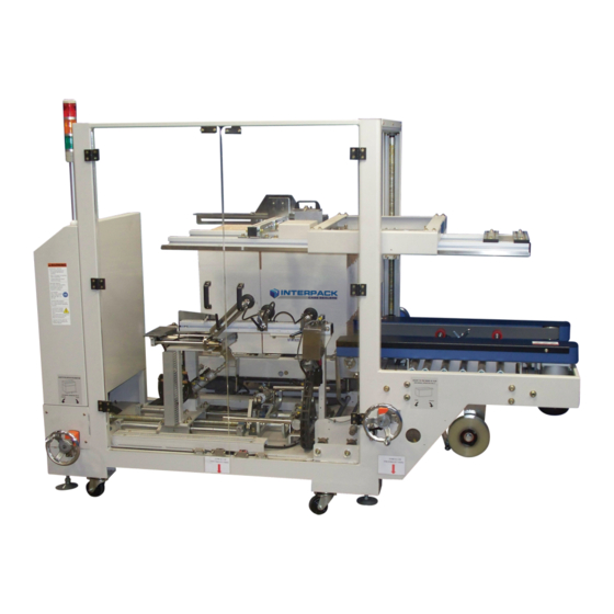
- Page 1 CE-12P Automatic Case Erector & Bottom Sealer OPERATION MANUAL & PARTS LIST This manual also available at www.itape.com.
-
Page 2: Table Of Contents
6 MACHINE SPECIFICATIONS ..............15 6.1 Power Requirements ................15 6.2 Specifications ..................15 7 MACHINE LAYOUT ..................16 7.1 CE-12P LAYOUT .................. 16 8 TROUBLESHOOTING ................17 9 DRAWINGS ....................19 9.1 Electrical ....................19 9.2 Pneumatic ..................... 26 10 PARTS ...................... -
Page 3: Service Instructions
1 SERVICE INSTRUCTIONS 1.1 Service This is the Intertape Model CE-12P Case Erector Sealing Machine you ordered. It has been set up and tested in our factory with Intertape brand tapes. If any problems occur when setting up or operating this equipment, please contact the authorized distributor from where you purchased this item. -
Page 4: Warranty
Intertape sells its Interpack Tape Heads, Case Tapers and Case Erectors with the following warranties: ... -
Page 5: Safety Issues
Keep belt guard and blade guards in place and in working order. Failure to comply with all of these warnings could lead to serious injury. Follow Lock-out Tag-Out procedure before servicing the equipment. Stay clear of moving parts which can shear and cut. CE-12P Manual USM8131... -
Page 6: Machine Installation
Connect power, compressed air and adjust pressure to 80 psi, and then open manual valve located near the exit of the CE-12P (Figure 4.1). After installation, adjust the height of working table to parallel with the height of your production line or conveyor. -
Page 7: Operating Instructions
The operator selects these modes by using a 2-position selector switch located on the main control panel of the machine (Figure 5.2). The CE-12P has installed standard two emergency stops and a control box for the rise and descent of the powered hopper table. -
Page 8: Button Functions
5.3 Button Functions Below table 5.1 shows all the buttons and switch functionality of your CE-12P Case Erector control panel (Figure 5.2). Control Panel Button Functions Power Lamp Indicator Machine is energized when lamp is on Power On Button Reset machine to the state of operation... -
Page 9: Stack Light Status
5.4 Stack Light Status Your CE-12P Case Erector is supplied with a status Stack Light Status indicator stack light. Table 5.3 shows the legend of each Legend light color machine status. CE-12P will flash as an Fault indication of a fault. The... -
Page 10: Set-Up
Up-Down control buttons to make adjustments effortlessly. For the initial set-up of your CE-12P for a particular size of case the Case Erector should be in manual mode and tape roll loaded. Follow the preceding steps below to set-up your CE-12P machine. - Page 11 13. The case should travel through the side belts without any hesitation and Figure 5.7 sealed on the bottom. Once the CE-12P is set-up to the desired Carton Hopper case size, the operator can now proceed to process cases automatically in automatic mode by switching the selector to “Auto.”...
- Page 12 Figure 5.10 No vacuum cups on this side after the case slot. Figure 5.11 is the vacuum cup mechanism, it secures the blank case to be pulled away from the hopper into the folding section. Figure 5.11 CE-12P Manual USM8131...
- Page 13 This will accelerate and reduce your set-up time when going back to the same case size, therefore, eliminating the set-up exercise (Figure 5.13). CE-12P Manual USM8131...
- Page 14 There are a total of three hand wheels and four position indicators. Figure 5.13 Figure 5.14 is the “No Tape” and “Low Tape” Sensors sensors. Tape Head Assembly Tape Roll Figure 5.14 CE-12P Manual USM8131...
-
Page 15: Machine Specifications
Operating Conditions – Use in a dry, relatively clean environment at 40º to 105º F (5º to 40º C) with clean dry cartons. Operating Range – 23” x 16” x 22” Max 10” x 7” x 4” Changeover Information – 7 Operations (5-10 minutes max) No tools, no change parts CE-12P Manual USM8131... -
Page 16: Machine Layout
7 MACHINE LAYOUT 7.1 CE-12P LAYOUT CE-12P Manual USM8131... -
Page 17: Troubleshooting
8 TROUBLESHOOTING Interpack Carton Sealers are fabricated with high quality components that provide trouble-free operation for a long period. However, should a problem occur, we recommend that you consult the following table before calling for service. If the problem you encounter is not discussed in this table, call Intertape Customer Service Department (see section 1.1 of this document). - Page 18 Not in Position Rear Flap Jam occurred. Clear jam. Folder Cylinder Not in Position Note: When Alarm Sounds; press “Alarm Reset” to stop alarm, and press and hold “Cycle Stop” button for 3 seconds to clear Troubleshoot Fault code. CE-12P Manual USM8131...
-
Page 19: Drawings
ELECTRIC CIRCUIT CE-12P Manual USM8131... - Page 20 CE-12P Manual USM8131...
- Page 21 CE-12P Manual USM8131...
- Page 22 CE-12P Manual USM8131...
- Page 23 CE-12P Manual USM8131...
- Page 24 CE-12P Manual USM8131...
- Page 25 CE-12P Manual USM8131...
- Page 26 AIR PRESSURE CIRCUIT CE-12P Manual USM8131...
-
Page 27: Pneumatic
Adapt FRONT FLAP FOLDING ASSEMBLY M3303-20B Part No. Description Q’ty M3303-B01 Front flap folder M3303-B02 Front flap folder mounting M3303-B03 Bearing bushing M3303-B04 Outfeed guide plate Q1-201203 Washer 81-3210 Cylinder 81-3224 Cylinder PHS10×1.25P Bearing E00-2110 Ball bearing CE-12P Manual USM8131... - Page 28 RBC2725 Cylinder LMA25LUU Connecting linear bearing UFL003 Connecting bearing HJ-63B-M8x20-B Handle MT030C Pulley 5/8”xL150 5x5x20L M3303-A13 Sensor base 81N-A110 Vacuum cup base 81N-A130 Vacuum cup base N9310-A32 Safety cover Q1-100606 Washer ASV410F-03-08S Valve LMA25LUU-AJ Connecting linear bearing CE-12P Manual USM8131...
- Page 29 CE-12P Manual USM8131...
- Page 30 LEFT & RIGHT FLAP FOLDING ASSEMBLY N9310-20C Part No. Description Q’ty M3303-C01 Pushing arm M3303-C02 Flap folding rod (1) M3303-C03 Flap folding rod (2) M3303-C04 Flap folding arm Q1-251403 Washer 81-4010 Cylinder 81-4024 Cylinder base PHS14×1.5P Rod-eye bearing UCP204 Connecting bearing CE-12P Manual USM8131...
- Page 31 L6303-D19 Solenoid valve guard 81N-2F3275 Cylinder 81N-TN327 Cylinder CG-032-24A Cylinder bracket FC-1010F Floating joint DA0912A-635-I-17-O Gauge E00-2110 Ball bearing 0450-21 Wire guard LF-1910ZZ Ball bearing LMA25LUU Connecting linear bearing LMF-16LUU Flanged linear bearing PHS10×125P Rod eye bearing CE-12P Manual USM8131...
- Page 32 Part No. Description Q’ty Q1-201204 Washer SF16×315L Linear shaft SF25×575L Linear shaft SH25A Shaft bracket SH16A Shaft bracket UCP203 Connecting bearing HO-6” Hand wheel C-R32 C circlet HJ 45B M6×25 B Handle 45B M6×25 Indicating finger CE-12P Manual USM8131...
- Page 33 SAFETY DOOR ASSEMBLY N9310-20E Part No. Description Q’ty M3303-E01 Door M3303-E06 Control box cover L6303-E06 Magnet plate L6303-E11 Top magnet base L6303-E12 Bottom magnet base HAND-14121 Handle FDM0640-8A Magnet FHI0645-B Hinge CE-12P Manual USM8131...
- Page 34 DA0912A-4.23-E-17-O C Gauge MT030C Pulley 6203ZZ Ball bearing 6303ZZ Ball bearing 7303A ZZ Ball bearing E00-2080-R60 Motor (1/4HP, 1:60) 5/8”×150L M3303-120 Finger 81N-1250 Sticker fix plate RS40×43 Chain N9310-130 Wiring box E6-002 Wiring box cover E3-043A Bracket CE-12P Manual USM8131...
- Page 35 CE-12P Manual USM8131...
- Page 36 K9319-163 Shaft bracket K9319-165 Bracket (L&R) K9319-168 Turning shaft 818-107A Washer LA316-118 Holding shaft (1) LA316-152 Holding shaft (1) BA81-1290 Holding shaft (2) EZ-064 Bushing 6805ZZ Ball bearing 6902ZZ Ball bearing E00-2080-R60 Ball bearing 1/4HP, 1:60 Motor CE-12P Manual USM8131...
- Page 37 Chain sprocket RS141315A Chain sprocket RS141325 Chain sprocket RS14150E Chain sprocket RS141525A Chain sprocket SF25×1442L Linear shaft A72-1370 Limit switch UFL005 Connecting bearing RS40×43 Chain RS40×222 Chain 843-K144 Chain 8×7×25L Round end key 8×7×50L Round end key CE-12P Manual USM8131...
- Page 38 FA310304 Supporting base (1) (L&R) FA310305 Supporting base (2) (L&R) M2005R00 Spacer ring M2007R01 Die block M2009R01 Tension sliding plate UPM-1029 Driving alu. pulley M2103 Driven alu. pulley 111501 Driven pulley 113300 Die block shaft DA0912A-6.35-E-17-O Gauge CE-12P Manual USM8131...
- Page 39 Linear shaft U73-2070 Hex. screw U73-2080 Die spring UCPA204 Connecting bearing 6203ZZ Ball bearing R12ZZ Ball bearing UFL003 Connecting bearing HO-6” Hand wheel 81N-3046 PVC belt (1855L×50W) HSD-2000ET-II Tape head C-S19 C circlet C-R32 C circlet HJ-45B-M6×25-B Handle CE-12P Manual USM8131...
- Page 40 CE-12P Manual USM8131...
- Page 41 Bracket M3303-111 Gear (1) M3303-112 Gear (2) M3303-405A Height adjusting shaft M3303-407 Top beam cover M3303-408 Lock block base, adjusting rod M3303-409 Adjusting rod guard 60049 T nut HAND-14121 Handle 6203ZZ Ball bearing DA0912A-4.23-I-17-O Gauge DEC-4040(ABS) Guard CE-12P Manual USM8131...
- Page 42 Part No. Description Q’ty HJ-45B-M6-25-B Handle HJ-63B-M8-20-B Handle SB-1200 Balancer UFL003 Connecting bearing HO-6” Handle RS35×176 Chain N9310-412 Top unit adjusting plate M3303-410 Weight balance block 15*60*330L Weight balance compressing plate 2 CE-12P Manual USM8131...
- Page 43 ELECTRIC CONTROL BOX N9310-600 Part No. Description Q’ty M3303-601 Electric control box 81NFA-602 Electric control box cover 81NFA-603 Wiring plate M3303-604 Electric control box name plate CE-12P Manual USM8131...
Need help?
Do you have a question about the CE-12P and is the answer not in the manual?
Questions and answers