
Subscribe to Our Youtube Channel
Related Manuals for One Stop Systems Gen2 ExpressBox 16 - Smart


Summary of Contents for One Stop Systems Gen2 ExpressBox 16 - Smart
- Page 1 Gen2 ExpressBox 16 - Smart EB16 Smart Expansion Systems 16 Slot PCI Express® Expansion System User Manual SKU: EB16-SX8 www.onestopsystems.com...
-
Page 2: Table Of Contents
One Stop Systems Table of Contents Preface Advisories Safety Instructions Introduction General Specifications Basic Features Smart Features Specifications EB16 Smart Main Components Basic Main Components Pre-Installation Parts List Tools Required for Installation Hardware Installation Guidelines for Installation Open Enclosure Remove Card Holder Assembly... -
Page 3: Pci-E Info For Configuration
One Stop Systems 3.2.3 Expansion Slot Utility 3.2.4 Apple System Profiler 3.2.5 Linux System Should Be Up and Running Other Technical Information PCIe slot Power Redundant Power Supply Option Interface Cards 4.3.1 x16 Interface Card LEDs 4.3.2 x16 Card Bandwidth / Lane Settings 4.3.3... - Page 4 One Stop Systems SLOT MANAGEMENT REMOTE MANAGEMENT / MANAGE 5.10 PCI-E INFO 5.11 Partitioning 5.11.1 Configuration 1 5.11.2 Configuration 2 5.11.3 Configuration 3 5.12 How to partition the EB16-SMART 5.13 Configuration and PCI-E Info profile 5.13.1 PCI-E Info profile for Configuration 1 5.13.2...
-
Page 5: Preface
One Stop Systems Preface Advisories Five types of advisories are used throughout this manual to provide helpful information, or to alert you to the potential for hardware damage or personal injury. NOTE Used to amplify or explain a comment related to procedural steps or text. - Page 6 One Stop Systems Disclaimer: We have attempted to identify most situations that may pose a danger, warning, or caution condition in this manual. However, OSS does not claim to have covered all situations that might require the use of a Caution, Warning, or Danger indicator.
-
Page 7: Safety Instructions
One Stop Systems Safety Instructions Always use caution when servicing any electrical component. Before handling the OSS Expansion chassis, read the following instructions and safety guidelines to prevent damage to the product and to ensure your own personal safety. Refer to the “Advisories” section for advisory conventions used in this manual, including the distinction between Danger, Warning, Caution, Important, and Note. - Page 8 One Stop Systems Static electricity can harm system boards. Perform service at an ESD workstation and follow proper ESD procedures to reduce the risk of damage to components. OSS strongly encourages you to follow proper ESD procedures, which can include wrist straps and smocks, when servicing equipment.
-
Page 9: Introduction
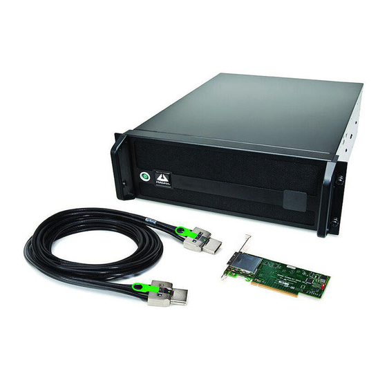
One Stop Systems Introduction General Specifications OSS ExpressBox 16 Smart is a 16-Slot PCI Express® Expansion System. The expansion system consists of a PCIe® host interface card, an iPass cable, a 4U rack-mount chassis containing a 16 Slot backplane and an expansion interface card, a standard or redundant power supply, and high volume cooling fans. -
Page 10: Smart Features
One Stop Systems Smart Features All the features of the BASIC model 14 slots x8 PCIe and 2 slots x16 PCIe OSS Express I/O Manager Constant critical component monitoring Front panel status LED display Specifications Item... -
Page 11: Eb16 Smart Main Components
One Stop Systems EB16 Smart Main Components The 3 expansion interface cards are optional. They are ordered separately. ExpressBox 16 Smart | 11... -
Page 12: Basic Main Components
One Stop Systems Basic Main Components ExpressBox 16 Smart | 12... -
Page 13: Pre-Installation
One Stop Systems Pre-Installation Before using the OSS Expansion chassis, you should perform the following steps: • Inventory the shipping carton contents for all of the required parts • Gather all of the necessary tools required for installation • Read this manual... - Page 14 One Stop Systems ExpressBox 16 Smart | 14...
-
Page 15: Tools Required For Installation
One Stop Systems Tools Required for Installation To complete the installation of the OSS product you will need a Phillips-head screwdriver and ESD wrist strap to prevent electrostatic discharge. ExpressBox 16 Smart | 15... -
Page 16: Hardware Installation
One Stop Systems Hardware Installation Guidelines for Installation The following steps will guide you through the installation of your OSS Expansion System. CAUTION Hardware installation shall be performed only by qualified service personnel per UL and IEC 60950-1. Electrostatic Discharge (ESD) Warning All add-in cards are susceptible to electrostatic discharge. -
Page 17: Open Enclosure
One Stop Systems Open Enclosure Loosen the 2 thumbscrews that retain the top cover of the chassis and slide the lid towards you as shown below: Remove Card Holder Assembly Remove the screw on the side of the cardholder assembly and lift upwards. - Page 18 One Stop Systems CAUTION Before touching anything inside the enclosure, move to an ESD station and follow proper ESD procedures. Failure to do so may result in electrostatic discharge, damaging the computer or its components. For more information, see “Protecting Against Electrostatic Discharge”...
- Page 19 One Stop Systems In model EB16-BX4 all sixteen slots are x4 PCIe Gen 2 as shown this diagram: PCIe PCIe Switch Switch For Model EB16-BX8 and EB16-SX8, a mixture of x8 and x16 PCIe Gen 2 slots are available as shown in this diagram.
-
Page 20: Install Host Card
One Stop Systems Install the cards following the card manufacturer’s recommendations. Some card manufacturers recommend that you install their software driver(s) prior to installing the hardware. If this is the case, be sure to install the PCIe device driver before installation of the expansion chassis. -
Page 21: X8 Interface Card
One Stop Systems When the host computer is off and all power cords are disconnected from the AC outlet, remove the cover and prepare your host card for insertion into a PCIe slot. There two types of host interface cards to use. You can use the x8 or x16. See photos below. -
Page 22: Which Slot To Plug In The Host Card
One Stop Systems 2.5.3 Which slot to plug in the host card It is important to know how many lanes the host computer slot can support. The host card needs to be configured for the same number of lanes as the host computer slot. For example, the computer slot is set to x8 lanes; therefore, you must configure the OSS host card to x8 lanes. -
Page 23: Host Mode Dipswitch Setting
One Stop Systems 2.5.4 Host mode Dipswitch Setting When the OSS interface card is used as “Host” interface i.e. installed in the host computer, the RED switch should remain OFF. Move the dipswitch to the ON position only if the same card is used as an “Expansion Interface” in the OSS expansion backplane. The x8 and x16 PCIe interface cards have the dipswitch to change between different modes (host and expansion). -
Page 24: Expansion Mode Dipswitch Setting
One Stop Systems 2.5.5 Expansion mode Dipswitch Setting The OSS “host” interface is the same card as the “expansion” interface only that its SW1 or SW2 switch is set to “ON=EXP.” By default, the expansion interface card should already be installed in the Expansion chassis. -
Page 25: Connect Cables
One Stop Systems Connect Cables Depending on the interface cards, a x16 PCIe or x8 PCIe 3-meter iPass cable is included. Carefully position the expansion chassis so that the expansion cable will conveniently reach from the host computer to the OSS Expansion chassis. -
Page 26: Connect Power Cables
One Stop Systems NOTE If possible, plug all power cords from the expansion chassis and your host computer into a shared power strip, preferably one that has surge and noise suppression circuitry built into it. Connect Power Cables Connect the power cable to the power receptacle of the power supply located on the back of the unit. For EB16 Smart, you need two power cables and one power cable for EB16 Basic. - Page 27 One Stop Systems Check your installation before powering up the OSS Expansion chassis for the first time. Although the power supply has an over voltage protection device built into it, it may not "trip" in time to fully protect a device that has been improperly connected, or whose power cable has been damaged.
-
Page 28: Power On Computer
One Stop Systems NOTE The power supply switch cannot be toggled quickly from ON to OFF after the expansion set is initially powered. There is a few seconds delay to power the device down. Power ON Computer To effectively use your OSS chassis as part of your computer system, ensure that all the proper connections are made. Then power on your computer. -
Page 29: Software - Verify Installation
One Stop Systems Software - Verify Installation 3.2.1 Windows OS No additional software or drivers are needed. The operating system should automatically recognize the OSS expansion chassis. To verify a successful installation on Windows, find the ‘My Computer’ icon and “right-click” on it. Then select ‘Manage’ from the pop-up menu. -
Page 30: Mac Os
One Stop Systems The Device Manager will display the available slots within the chassis. As reference, you can determine which slot you inserted your PCIe card in by following the outline that is shown below. The OSS chassis has 2 PCIe Switch devices that enable the slots to work: ... -
Page 31: Apple System Profiler
One Stop Systems Mac OS X is prompting you to choose a PCI Express profile that maximizes the performance of your attached devices. The OSS host interface card can communicate up to a bandwidth of x16, x8, or x4 from and to the expansion chassis and devices. Again, you have to verify the configuration of your card. -
Page 32: Linux
One Stop Systems 3.2.5 Linux After the expansion chassis has been installed in a Linux-based system, its installation can be verified by typing the following command lines: lspci –t Display the overall structure of the expansion chassis lspci –vv Lists additional information about the PCIe switch (in our case it will list the PLX information). -
Page 33: Other Technical Information
One Stop Systems Other Technical Information PCIe slot Power Be AWARE of the power consumption of any 3rd party card that is inserted into the slot of the device. Each individual slot is capable of outputting 75 Watts of power. If at any time the cards inserted exceed the maximum amount of power that is available from every slot, then one power supply would not suffice. -
Page 34: Redundant Power Supply Option
One Stop Systems Redundant Power Supply Option The Power Supply units that are used within this chassis are shared by the electrical components within the chassis. Both units effectively distribute power until one unit becomes nonoperational. In this case, the effect of power distribution is shifted to the functional Power Supply. -
Page 35: Interface Cards
One Stop Systems NOTE CONNECTORS J20, J21, J22, and J23 within the chassis will provide additional power to any PCI Express Card that requires it. The outputs from these connectors are 12V @ 10A each. Users should purchase a OSS cable P/N# 01-05996-03 for this capability. -
Page 36: X16 Card Bandwidth / Lane Settings
One Stop Systems 4.3.2 x16 Card Bandwidth / Lane Settings The width of the active data lanes may vary based on the PCIe slot that you are using for your OSS host interface card. Be sure to check the PCIe slot in your computer to determine how many data lanes it can support. -
Page 37: X8 Interface Card Leds And Lane Settings
One Stop Systems 4.3.3 x8 Interface Card LEDs and Lane Settings The card that is x8-capable (uses x8 iPass cable) contains status indicators that tell users the condition it is currently operating in. There are LED indicators for the lanes that are being used for data transfer and whether the board is powered correctly. A switch is also available to change the amount of lanes that would be operational for usage by the user. -
Page 38: Backplane
One Stop Systems Backplane This is current (new) EB16 backplane. ExpressBox 16 Smart | 38... -
Page 39: Backplane Block Diagram
One Stop Systems There are 17 slots in the EB16 unit, from slot 0 to slot 16. Slot0 is the designated slot for expansion interface card. There are three x16 PCIe slots and thirteen x8 PCIe slots. Main board (with 16 slot PCIe slots) is Gen 2 with PLX PCIe switch. -
Page 40: Backplane Faqs
One Stop Systems Backplane FAQs Question#1 How many lanes are available on EB16? Answer: There are 192 Lanes Available Question#2 There are two switches on the EB16. How many lanes are in-between these two or lanes allocated per switch? Answer: Total allocated 96 lanes on first Switch station 1 (From slot1 to slot6) ... -
Page 41: Backplane Dipswitches
One Stop Systems Backplane Dipswitches The following dipswitches on the EB16 board are for internal manufacturing use only for programming EEPROM. SW2, SW4, SW5 , SW7, SW9, SW10, SW11 DO NOT TOUCH THIS!!! DO NOT CHANGE SETTINGS!! Changing or moving the dipswitches will corrupt the EEPROM, which will render the slots or the entire expansion board non-operational. - Page 42 One Stop Systems ExpressBox 16 Smart | 42...
-
Page 43: Backplane Power Supply Connectors
One Stop Systems Backplane Power Supply Connectors The pictures below are the two female Power Supply connectors (18-pin connector) on the main board / backplane. These are the four Auxiliary power connectors available on the main board / backplane. It is a10-pin power connector. -
Page 44: Auxiliary Power Cables
One Stop Systems Auxiliary Power Cables There are two types of auxiliary power cables available for the EB16 units (Smart and Basic models), the 6/8-pin aux cable (SKU#: 01-05996-04) and the 4-/6-pin aux cable (SKU#: 01-05996-03) . The cables are sold separately, you need to contact OSS Sales to order the item. - Page 45 One Stop Systems ExpressBox 16 Smart | 45...
-
Page 46: Backplane Leds
One Stop Systems 4.10 Backplane LEDs 4.10.1 Power Management Backplane This backplane system controls the power distribution to the entire PCIe device. Ensure that this device is working properly by indicating that the LEDs are ON. It is attached to the side panel within the chassis near the power supply module. - Page 47 One Stop Systems Other indicators that are located on the backplane are the LEDs that identify the type of card that is inserted into a slot. This is in regards to the number of lanes and speed that the card possesses. As shown below, the LEDs are located at the bottom of each individual slot.
-
Page 48: Led Indicators And Configuration Switches
One Stop Systems 4.11 LED Indicators and Configuration Switches NOTE: ExpressBox 16 Smart Only Under normal operating conditions, the status indicators are for internal OSS troubleshooting while the configuration switches/jumpers should remain in their default state preset by OSS for best compatibility. However, should a problem occur with the chassis (or a special mode of operation be solicited by the client) we included below explanations as to what all these items are and how they should be treated: 4.11.1 Status Front Panel Indicators... -
Page 49: Power Supply Indicator Leds
One Stop Systems 4.12 Power Supply Indicator LEDs If the LED stays Orange after replacing or swapping the faulty component, you have to reset the SNMP to factory default settings. Hold the Alarm Reset button (see picture below) until the LEDs blink. The color of the entire LEDs will turn orange and the device will reboot to its... -
Page 50: Flashing The Netburner
One Stop Systems 4.15 Flashing the Netburner This method allows you to reload the existing program or update with a new program. How to Update the SNMP / Net Burner on Windows OS Connect Ethernet Cable to Laptop Connect the Other end of Ethernet cable to expansion unit Plug in one power cord to the power supply (do not turn ON the unit);... - Page 51 One Stop Systems Launch the AutoUpdate.exe by "double clicking" the AutoUpdate.exe . Click FIND button, select Device, and then click OK Check the Reboot box Click on "Browse", select the ……._APP.s19, then click “Open ExpressBox 16 Smart | 51...
- Page 52 One Stop Systems Click update Login Authentication screen will come up, enter User Name: default and Password: OSS 10. Click OK, to initiate programming 11. When done programming / updating, “Message Prompt” will come up "Programming completed without error. 12. Click OK 13.
- Page 53 One Stop Systems 15. Refresh the browser page, the configuration page will come up, go to drop down box and select PE16RR-RAS2 4U 2XPSU and Click the Go button 16. SNMP Web GUI will come up, on the upper right hand of the web you'll see the updated version "Express I/O Manager 1.9.4...
-
Page 54: Configure Network Setting
One Stop Systems 4.16 Configure Network Setting Configure your computer’s network setting to correlate to the default IP address of the OSS chassis . The IP address of the OSS chassis is 192.168.1.10 Set your network settings to configure manually and enter an IP address for your computer of 192.168.1.20 where 20 can really be any free number other than 10. -
Page 55: Express I/O Manager
One Stop Systems Express I/O Manager ExpressBox 16 Smart contains extra features that could be utilized to monitor the status of the components on the backplane and the items in the chassis such as the state of the power supplies, fan status, and temperature. It is observed on a remote computer that would indicate when an equipment malfunction has occurred. -
Page 56: Home
One Stop Systems The define username will be “default” and the password to be “OSS”. The user will be directed to the OSS home webpage for the expansion device. HOME The homepage provides an overview for the status of the chassis. It allows you to view the number of fans, power supplies, and temperature sensors that is attached to your chassis along with the number of users that has access to the device. -
Page 57: Administrator
One Stop Systems ADMINISTRATOR The device is capable of allowing separate users have access to the PCIe system. Based on the MODE that the device is operating in, a maximum of 4 users could share the same Expansion set. To add users, click on the check-box and then enter their name under Enable/Disable Users. You would then configure their setting based on login information and remote monitoring. -
Page 58: Alarm Settings
One Stop Systems ALARM SETTINGS With the SNMP built into the chassis, you can oversee the configurations that are used to set off an alarm whenever there is a malfunction with the equipment pertaining to the interior of the chassis. This feature is shown on Alarm Settings. These settings are recommended to stay at its default condition. -
Page 59: Network
One Stop Systems NETWORK The Network tab allows you to change your IP address. It can also permit or prevent certain IP addresses from accessing the extended feature of the chassis. ExpressBox 16 Smart | 59... -
Page 60: Slot Management
One Stop Systems SLOT MANAGEMENT Slot Management is another user-friendly interface that allows you to partition the slots into separate groups. This feature enables multiple computers to use one device at the same time. You would have 3 options to choose from on how the slots would split up. After selecting a different configuration, you have to restart your computer and chassis. -
Page 61: Remote Management / Manage
One Stop Systems REMOTE MANAGEMENT / MANAGE Remote Management is a feature that is available through the SNMP. You have the option of configuring the alarm to be ON and in alert mode while the chassis is powered by clicking on Turn On Audible Alarming Feature. At default, this alarm should already be activated. -
Page 62: Pci-E Info
One Stop Systems 5.10 PCI-E INFO The PCI-E Info page contains status on the individual slots of the backplane device. The information that is available on this page provides you with an overview of what speed it is running on and how many lanes the slot is using. This variation is based on the PCI-Express card that is inserted into the slot. -
Page 63: Partitioning
One Stop Systems 5.11 Partitioning This feature is only available on EB16-SMART model. Within PCI Express switching, there is a capability to partition the PCI Express topology such that multiple hosts can communicate with peripherals through the same switch silicon but be fenced off (isolated) from other segments. -
Page 64: Configuration
One Stop Systems 5.11.2 Configuration 2 Slot 0, Slot 3, Slot 6 and Slot 9, these are the upstream ports, which mean an expansion interface card is present in the PCIe slot. Slot 0, Slot 3 and Slot 6 are x16: You can plug in a x16 or x8 interface card. If you do not have a x16 interface card you can use a x8 card, but it will run at x8. -
Page 65: How To Partition The Eb16-Smart
One Stop Systems 5.12 How to partition the EB16-SMART Connect Ethernet cable to EB16 RJ45 port Connect the other end of Ethernet cable to laptop or computer Plug in the power cable to EB16 power supply receptacle. Do not turn ON the EB16 unit yet, leave the unit on standby mode. -
Page 66: Configuration And Pci-E Info Profile
One Stop Systems 5.13 Configuration and PCI-E Info profile Each partition-configuration has a designated PCI-E Info profile. Three configurations have different PCI-E info. The following photos will show you the PCI-E Info profile per configuration. 5.13.1 PCI-E Info profile for Configuration 1 5.13.2 PCI-E Info for Configuration 2... - Page 67 One Stop Systems 5.13.3 PCI-E Info for Configuration 3 ExpressBox 16 Smart | 67...
-
Page 68: Chassis Maintenance
One Stop Systems Chassis Maintenance Like all computer systems, you will need to perform some routine maintenance tasks. Some of these include making sure that the air vents in the chassis are clear of obstructions and that the cooling air from the fans flows freely. You will also need to check the foam filter behind the front panel to ensure it is clean, thus allowing for unrestricted air flow to the fans. - Page 69 One Stop Systems Be sure to keep the can of compressed air about six inches from the parts being sprayed with air. Pay particular attention to the fans in the chassis and power supply because they are critical to air movement and to keeping your chassis cool. Also spray the slots on the backplane Next, you can use anti-static wipes to wipe down any open areas inside and outside of the chassis to remove any remaining dust or dirt.
-
Page 70: Fan Replacement
One Stop Systems Fan Replacement ExpressBox 16 is designed to allow “hot-swappable” fan replacement while the chassis is powered on. First you will need to remove the chassis lid. Then locate the fan that has failed, unlock its thumbscrew, lift up its metal tab and pull it out. -
Page 71: Power Supply Replacement
One Stop Systems Power Supply Replacement In spite of regular performance of routine maintenance tasks, some computer systems can experience hardware failures. Fortunately, your investment in a OSS Expansion chassis with a redundant power supply provides you with the ability to easily replace a power module in the event of a failure. - Page 72 One Stop Systems IMPORTANT In order to ensure the safety and efficiency of your expansion chassis, it is recommended that you keep a spare power supply module on hand – just in case. Protect yourself, keep a spare. Order your spare power supply module from OSS –...
-
Page 73: Troubleshooting
One Stop Systems Troubleshooting Locate the Problem If you are having trouble with the OSS Expansion chassis, first verify that all cards and cables are seated properly. Be sure you followed the instructions in earlier sections of this manual. Always remember to power On and Off correctly when rechecking your installation. If you are still having problems, try these troubleshooting steps: The OSS expansion chassis is correctly displayed as a “PCI standard PCI-to-PCI bridge”... -
Page 74: Computer Doesn't Detect The Expansion System
One Stop Systems Computer Doesn’t Detect the Expansion System If the expansion chassis is not visible in your Windows Device Manager or your Apple System Profiler at all, you will need to turn off your computer (first) and then the OSS Expansion chassis (second) and test all cords and cables to ensure you have everything connected correctly. If... -
Page 75: Add-In Pcie Card Not Recognized
One Stop Systems Add-in PCIe card not recognized Shut down the computer followed by the OSS Expansion chassis Remove the card displaying a problem Replace the “problem card” with a simple card, such as an Ethernet card that has drivers built into the operating system. (Using this “type of card”... -
Page 76: Support For 3 Rd Party Pcie Cards
One Stop Systems Support for 3 Party PCIe cards OSS will provide reasonable technical support to with 3rd Party cards. However, if you have verified a successful installation of the OSS Expansion chassis but experience difficulty installing your 3rd Party cards, the card manufacturer should be able to provide the best support. -
Page 77: Computer Hangs After Many Card Installed
One Stop Systems Computer Hangs after Many Card Installed Any expansion chassis configuration requires the cooperation of the computer system’s BIOS in order to operate properly, regardless of the platform (PC/Laptop/Server) or operating system (MS Windows/MACOS/LINUX etc.). The BIOS hosts the first and the most fundamental code (firmware) that a computer executes upon boot-up. It is then that each PCI/PCIe add-in card (be it located on the host system or on OSS’s expansions chassis) is allocated Input/Output memory space for proper operation. -
Page 78: How To Get More Help
If factory service is required, a Service Representative will give you a Return Merchandise Authorization (RMA) number. Put this number and your return address on the shipping label when you return the item(s) for service. Please note that One Stop Systems WILL NOT accept COD packages, so be sure to return the product freight and duties-paid. -
Page 79: Appendix A Compliance
One Stop Systems Appendix A Compliance NOTE: This equipment has been tested and found to comply with the limits for a Class A digital device, pursuant to part 15 of the FCC Rules. These limits are designed to provide reasonable protection against harmful interference when the equipment is operated in a commercial environment. - Page 80 One Stop Systems Manual P/N 09-09979-00 Rev C ExpressBox 16 Smart | 80...
Need help?
Do you have a question about the Gen2 ExpressBox 16 - Smart and is the answer not in the manual?
Questions and answers