Advertisement
Quick Links
Installation, Set-up and Operating Instructions
Stock Ref. Nos.
W IRED
456166A (9" W L)
456167A (9" PL)
456174A (12" W L)
456175A (12" PL)
READ INSTRUCTIONS IN CONJUNCTION W ITH ILLUSTRATIONS
(Community Design Nos. 000112507-0001-0004 & 000112065-0001)
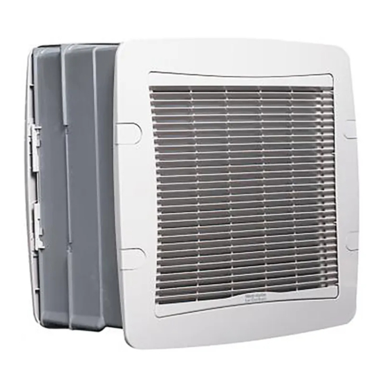
T-SERIES
W all & Panel Models
W IRELESS
456170A (9" W L)
456171A (9" PL)
456178A (12" W L)
456179A (12" PL)
230V/1/50Hz
READ AND SAVE THESE INSTRUCTIONS
Advertisement

Related Manuals for Vent-Axia LoWatt T Series


Summary of Contents for Vent-Axia LoWatt T Series
- Page 1 T-SERIES W all & Panel Models Installation, Set-up and Operating Instructions Stock Ref. Nos. W IRED W IRELESS 456166A (9" W L) 456170A (9" W L) 456167A (9" PL) 456171A (9" PL) 456174A (12" W L) 456178A (12" W L) 456175A (12"...
- Page 2 READ INSTRUCTIONS IN CONJUNCTION WITH THE ILLUSTRATIONS IMPORTANT THE FAN MUST BE SITED AND CONNECTED IN ACCORDANCE WITH CURRENT IEE REGULATIONS (UK) OR THE APPROPRIATE STANDARDS IN YOUR COUNTRY. THIS APPLIANCE IS NOT SUITABLE FOR INSTALLATION IN A SHOWER CUBICLE OR ENCLOSURE AND MUST BE SITED AWAY FROM ANY SOURCE OF WATER SPRAY, AND MUST BE OUT OF REACH OF A PERSON USING A FIXED BATH OR SHOWER.
-
Page 3: Fan Dimensions
FAN DIMENSIONS Before commencing work, study the tables shown in figures C1/ C2 – WALL INSTALLATION and C3/ 4 – PANEL INSTALLATION to ensure fan will fit in position proposed. • The Wall Fan is suitable for installation in walls between 240mm to 315mm thick, using the two wall liner sections provided. -
Page 4: Preparation For Installation
E7 Refit the housing ensuring that no internal wires are trapped between the housing and base. E8 Engage the two side catches. Tighten the two side catch screws. E9 Replace the grille with the louvres slanting upwards and the Vent-Axia logo at the bottom, then secure with the retaining screw. - Page 5 FOR SPEED CONTROL REFER TO THE RELEVANT FITTING AND WIRING INSTRUCTIONS SUPPLIED WITH THE WIRED/ WIRELESS CONTROLLER. E10i E10ii WIRING THE CONNECTOR SOCKET WARNING THIS APPLIANCE MUST BE EARTHED F1 Remove the top cover from the connector socket by undoing the 2 retaining screws. F2 Lift up lever and slide out top cover.
- Page 6 Fig 2 Using an On/Off switch: Connect the mains supply to the fan connector socket. Fig 3 Auxiliary sensor switching: Connect the mains supply to the fan connector socket. F6a Place the fan partially into the wall liner and replace the connector socket by pushing positively into position.
- Page 7 Fig. 3 WIRED VERSION ONLY ISOLATE FROM THE POWER SUPPLY PRIOR TO ANY MAINTENANCE AND CLEANING USER INSTRUCTIONS • At intervals appropriate to the installation, inspect and clean the fan to ensure there is no build up of grease or dirt on the impeller or the motor. •...
- Page 8 REASSEMBLY - ALLOW THE COMPONENTS TO DRY BEFORE REASSEMBLY G16 Replace the outdoor grille with the louvres slanting downwards and the Vent-Axia logo at the top grille. G17 Align the impeller with the locating pins on the motor shaft. With a sharp push, replace the impeller back onto the motor shaft.
-
Page 10: Vent-Axia Sales Centres
‘Guarantee Claim’ stating the nature of the fault and providing proof of the date and source of purchase. As part of the policy of continuous product improvement Vent-Axia reserve the right to alter specifications without notice Head Office: Fleming Way, Crawley, West Sussex RH10 9YX...
Need help?
Do you have a question about the LoWatt T Series and is the answer not in the manual?
Questions and answers