Table of Contents
Advertisement
Quick Links
OPERATION
&
MAINTENANCE
MANUAL
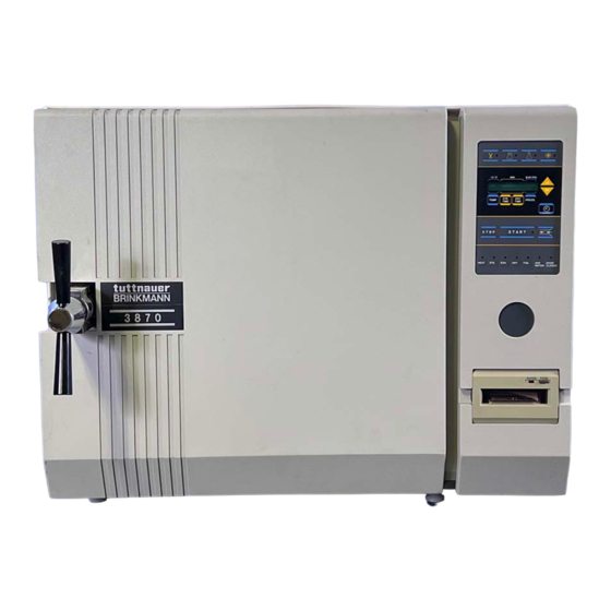
Electronic Table -Top Autoclaves
models 1730, 2340, 2540, 3545, 3850, 3870E
2340, 3850, 3870 EA
2450EK
MAN205-0112-003E Rev. D
Cat. No.
Brinkmann Instruments, Inc., One Cantiague Road. P.O. Box 1019, Westbury, NY 11590-0207,
(800) 645-3050,
Fax: (516) 334-7506
Brinkmann Instruments (Canada) Ltd., 6670 Campobello Road, Mississauga, Ontario L5N 2L8,
(800) 262-8715,
Fax: (905) 826-5425
Advertisement
Table of Contents

Related Manuals for Tuttnauer 2450EK


Summary of Contents for Tuttnauer 2450EK
- Page 1 MAINTENANCE MANUAL Electronic Table -Top Autoclaves models 1730, 2340, 2540, 3545, 3850, 3870E 2340, 3850, 3870 EA 2450EK MAN205-0112-003E Rev. D Cat. No. Brinkmann Instruments, Inc., One Cantiague Road. P.O. Box 1019, Westbury, NY 11590-0207, (800) 645-3050, Fax: (516) 334-7506 Brinkmann Instruments (Canada) Ltd., 6670 Campobello Road, Mississauga, Ontario L5N 2L8,...
-
Page 3: Table Of Contents
T A B L E O F C O N T E N T S PARAGRAPH PAGE NO. GENERAL Incoming Inspection Warranty TECHNICAL DATA Introduction Stand – by heating mode Environment Emission Information Operating Conditions Utilities Construction Symbol Description Electrical Data Specifications 2.10 Technical Specifications... - Page 4 T A B L E O F C O N T E N T ( C o n t . ) PARAGRAPH PAGE NO. PREPARATION BEFORE STERILIZATION OPERATING INSTRUCTIONS MAINTENANCE INSTRUCTIONS Preventive and Scheduled Maintenance Replacing the Air Filter (models EA) Draining the Reservoir Cleaning Air Jet Replacing the Door Gasket...
- Page 5 T A B L E O F C O N T E N T ( C o n t . ) DRAWINGS PAGE NO. Front View Rear View Front Panel Keyboard Page 3 of 53 Pages...
-
Page 6: General
TECHNICAL DATA Introduction This table-top autoclave is designed for the sterilization of wrapped and unwrapped instruments and related items found in dental, medical and veterinary clinics, first aid rooms, hospitals, laboratories etc. This autoclave is an electrically - heated sterilizer using steam as the sterilizing agent. - Page 7 Tuttnauer. All Tuttnauer products are carefully inspected prior to shipment and all reasonable precautions are taken in preparing them for shipment to assure safe arrival at their destination.
-
Page 8: Operating Conditions
Operating Conditions This device is to be used for indoor use. This autoclave is intended for NORMAL environment conditions as follows: ● - Altitude up to 2000m. ● - Room temperature range 5ºC to 40ºC. ● - Installation Category II. ●... -
Page 9: Electrical Data
Electrical Data 1730 2340 2540 3545 3850 3870 E, EA E, EA EK E, EA E, EA Ampere (A) at 230/240V 10.4 10.4 Ampere (A) at 120V 11.7 11.7 20.0 Watts (W) 1050 1400 1400 2200 2400 2400 3000 Frequency 50 / 60 Hz Degree of protection by... -
Page 10: Specifications
Specifications Overall Dimensions Model 1730 2340 2540 3545 3850 3870 Dimensions 17.4 20.0 20.0 23.2 660 26.0 26.0 Overall 12.0 14.4 14.4 17.7 525 20.7 20.7 Dimensions 17.9 21.5 21.5 21.9 695 27.5 34.5 Maximum 29.5 35.8 35.8 39.0 1155 45.5 1335 53.0 dimensions 22.0 24.8... -
Page 11: Technical Specifications
Page 9 of 53 Pages... -
Page 12: Directives And Standards
2.11 Directives and Standards Every autoclave meets the provisions of the following Directives and is constructed in compliance with the following Standards: 2.11.1 Technical Directives 1. Medical device directive MDD/93/42/EEC. 2.11.2 Technical Standards 1. A.S.M.E. Code, Section VIII div.1 for unfired pressure vessels. 2. -
Page 13: Water Quality
2.12 Water quality The distilled or mineral – free water supplied to the autoclave should have the physical characteristics and maximum acceptable level of contaminants indicated in the table below: Physical characteristics and acceptable contaminants levels in water, for sterilizers Evaporate residue ≤... - Page 14 FRONT VIEW Description Reservoir water drain valve Model 1730 Ring for drain valve Door closing device Door switch Autoclave cover Water reservoir cover Water reservoir – assembly Safety valve Air relief valve Pressure gauge Validation port cover Main switch Printer Models 2340/2540 Front panel key board Completion to panel...
- Page 15 REAR VIEW only EA,EKA Cut-Out Thermostat Reset button Page 13 of 53 Pages...
-
Page 16: Keyboard (Keys And Display)
KEYBOARD (keys and display) FRONT PANEL KEYBOARD Note: See section 3.2 for a description of the Keyboard buttons Page 14 of 53 Pages... -
Page 17: Indicator Light Description
Indicator Light Description Programs Shows the selected program Indicators START Shows the system is running a program HEAT The system is currently in the Heating stage The system is currently in the Sterilization stage. The system is in the Exhaust stage. The system is in the Dry stage. -
Page 18: Description And Functions Of The Control Panel Keyboard
Description and Functions of the Control Panel Keyboard 3.2.1 program keys Unwrapped Instruments Wrapped Instruments Liquids (slow exhaust, no drying) Pressing one of the above program keys determines the chosen program. The program parameters are displayed and the program indicator lights. Dry Only Pressing this key allows inclusion of the Additional Drying procedure for a period of time determined by the operator. - Page 19 Pressing these keys in combination with TEMP. (5), STE TIME (6), DRY Time (7) and CLOCK (9) lowers these values. (10) CLOCK Pressing the CLOCK programming key displays the date, with the cursor under the day. Pressing the UP or DN keys changes the date.
-
Page 20: Description Of The Display Panel
(13) STOP This key issues the only command accepted by the system during the running of a program. Pressing this key for over 1 second causes the program to immediately cease running and enters the EXHAUST stage, at the end of which the “MAN. STOP”... - Page 21 Low Temp. Message is displayed, fail indicator lights and cycle is aborted, if the temperature drops 2.5ºC (4.5°F) below the required sterilization temperature. Possible causes: ♦ Insufficient water in the chamber (see Low water message) ♦ Sterilization time has been set for to long a period ♦...
- Page 22 Door Unlock Message is displayed and the DOOR CLOSED LED indicator remains unlit, if the door is improperly closed when the START button is pressed. If the door accidentally opens during any stage of the cycle, the same message appears, the DOOR CLOSED LED indicator will turn off, and the system reacts as if the STOP key was pressed.
-
Page 23: Sterilization Programs
STERILIZATION PROGRAMS The autoclave offers 3 sterilization programs, at a temperatures of 121°C (250°F), with or without a drying stage and 1 accessory (dry only) program. A. Three sterilization programs: 1. Unwrapped instruments 2. Wrapped instruments and porous loads. 3. Liquids B. -
Page 24: Program 2. Wrapped Instruments And Porous Loads
PROGRAM 2 . Wrapped Instruments and Porous Loads For wrapped instruments and materials, when the manufacturer recommends autoclaving at temperature of 121°C (250°F) with a drying stage. Nominal parameters default settings ♦ Sterilization temperature: 121°C (250°F) ♦ Sterilization time: 15 minutes ♦... -
Page 25: Program 3: Liquids
PROGRAM 3: Liquids For distilled water, solutions, medicines and other liquid preparations in closed bottles or flasks. Nominal parameters default settings ♦ Sterilization temperature: 121°C (250°F). ♦ Sterilization time: 30 minutes. ♦ Slow exhaust: 15 to 20 minutes. ♦ Drying time: drying is not allowed. Operations sequence: ♦... -
Page 26: Printer (Optional)
PRINTER (Optional) The printer is an optional device. If the autoclave is not equipped with a printer paragraph 5 is not applicable. Printer Operation The autoclave is equipped with a character printer, which prints a detailed history of each cycle performed by the instrument (for the record or for subsequent consideration). - Page 27 PRINTER OUTPUT DESCRIPTION Autoclave No:01 Number of the autoclave with respect to other units in the same location Load number: 0003 Load number. Useful to determine when to clean the chamber. (upon reaching 255 this number is reset to 0) Operator :___________ To be filled in manually by operator.
-
Page 28: Printer Handling
Printer Handling The printer is driven and controlled automatically by the control unit, while the autoclave performs a sterilization program. Figure 1 Figure 2 To set the paper roll in the printer perform the following steps: 5.2.1 Gently push the clips for removing the front panel, remove the panel and pull out the printer gently. -
Page 29: Installation Placing And Leveling Instructions
6.1.1 Setup for new units 2340, 2540, 3545, 3850 & 3870 Your new Tuttnauer Autoclave was set at the factory and requires a minimal of setup. ♦ Make sure the counter is level and sturdy ♦... - Page 30 6.1.2 Setup for units 1730 & any unit with serial number prior to 2003000 Proper adjustment of the chamber pitch is one of the most important things you can do for the sterilizer. Proper chamber pitch insures that among other things the sterilizer will have the proper amount of water in the chamber at the beginning of each cycle.
-
Page 31: Automatic Water Filling
For new units 2340, 2540, 3545, 3850 & 3870 The proper amount of water for automatic filling in your new Tuttnauer autoclave has been preset at the factory. However, if in routine operation, there is inadequate water in the chamber, the operator can adjust the level with the automatic built-in system by doing the following. -
Page 32: Lifting And Carrying
6.2.3 Checking the automatic fill To check the automatic fill, follow these steps: To check the automatic fill, follow these steps: Remove any water that is in the chamber. Make sure the unit is turned on. Place a collecting vessel under the autoclave's door. With the door open, press and hold the door switch, then press the START key. -
Page 33: Loading And Unloading The Device
Loading and unloading the Device 6.4.1 Safety Protective equipment and clothes and other safety instructions should be implemented in accordance with local and national regulations and/or rules! For proper sterilization - Do not overload the chamber. Only autoclavable products shall be used; please refer to the materials or instruments manufacturers instructions for sterilization of unknown materials or instruments. -
Page 34: Preparation Before Sterilization
1. Clean instruments immediately after use to remove any residue. It is recommended that all instruments be ultrasonically cleaned using Tuttnauer's CLEAN AND SIMPLE enzymatic cleaning tablets or other suitable solution. 2. After cleaning, rinse instruments under tap water for 30 seconds and pat or air dry to remove residual minerals. - Page 35 18. Do not stack pouches. It is recommended that a pouch rack such as the Tuttnauer POUCH RACK be used to insure proper steam penetration and adequate drying. Surfaces that are hidden because the items are being...
- Page 36 21. Liquids should only be sterilized in heat proof glass. The beaker should only be filled 2/3 full and the lid should be on loosely to allow for expansion. 22. If spotting is detected on the instruments the first step would be to use an ordinary eraser to remove the spot.
-
Page 37: Operating Instructions
OPERATING INSTRUCTIONS It is important to clean the hole of the air jet, as described in sec. 9.3 before starting operation of the autoclave, for the first time. 1. Remove water reservoir cover. Pour distilled water into the reservoir, through the opening on top of the autoclave, until it reaches the base of the safety valve holder, approximately 0.7 gallons (3 liters). - Page 38 8. During any program that has a drying stage scheduled, the dry stage begins after the steam exhaust stage. Models EA are equipped with an air compressor that during the drying stage, draws air through a HEPA filter (0.2µm), and pushes that air through the heated chamber and out the air outlet valve to remove moisture and facilitate the drying operation.
- Page 39 MAINTENANCE INSTRUCTIONS Page 37 of 53 Pages...
-
Page 40: Maintenance Instructions
The instructions that follow can easily be carried out by the office personnel and do not require a service technician. Should the need arise technical assistance or a serve technician can be requested by either calling your dealer or Tuttnauer USA. 9.1.1 Daily Clean door gasket with a mild detergent, water and a soft cloth or sponge. -
Page 41: Replacing The Air Filter (Models Ea)
Replacing the Air Filter (models EA) To facilitate drying the instruments with the door of the chamber closed, models EA are equipped with an air compressor and HEPA filter (0.2µm). During the drying stage the compressor draws air through the HEPA filter and forces the circulation of that air through the heated chamber to remove moisture from the wrapped instruments. -
Page 42: Draining The Reservoir
Draining the Reservoir Caution Before starting, ensure that the electric cord is disconnected and there is no pressure in the autoclave. The drain valve is located on the front left side of the autoclave after the door is opened. The function of the drain valve is to drain the water reservoir. -
Page 43: Cleaning Air Jet
Cleaning Air Jet (Located in the water reservoir.) A dirty air jet is the number one cause of failed spore tests The elimination of air from the sterilization chamber during heat up is critical to the proper operation of the autoclave. Failure of the air removal system will be responsible for incomplete sterilization, indicator strips that do not turn, failed spore tests and aborted sterilization cycles. -
Page 44: Replacing The Door Gasket
Replacing the Door Gasket Pull off the gasket from the door groove. Install the new gasket as described in drawings 1, 2 and 3 above. Caution! This gasket is designed with a trapezoidal cross section. The gasket should be placed with the widest side towards the door. Page 42 of 53 Pages... -
Page 45: Checking The Safety Valve
Checking the Safety Valve (Located in the water reservoir) In order to prevent the safety valve from becoming blocked, it is necessary to allow the steam pressure to escape through the valve. This procedure should be done every month as follows: 1. -
Page 46: Replacing The Cartridge Fuse
Replacing the Fuse Caution Make sure that the electrical power cord is disconnected! Use a screwdriver to unlock the fuse holder cover by turning it counter clockwise ¼ turn, and pull it out. Insert a new fuse into the holder and turn the cover clockwise until locked. -
Page 47: Cleaning Water Outlet Strainer
Cleaning water outlet strainer Caution! Before proceeding, Make sure that the electric cord is disconnected and there is no pressure or water in the chamber. Warnings 1. The strainer’s cover is HOT Do not touch the strainer’s cap, mounted on the exhaust line, during and shortly after operation. -
Page 48: Cleaning Table Top Autoclaves With Chamber Brite
Cleaning Table Top Autoclaves with Chamber Brite ™ CHAMBER BRITE ™ is a cleaning and descaling agent designed specifically for the cleaning and removal of water deposits, oxides and other sediments that are found in steam sterilizers. The material is a combination of acidic salts and additional cleaning materials. - Page 49 10. Remove the tray holder; rinse and wipe the interior of the chamber with a damp cloth. 11. Fill the reservoir with distilled water or mineral free water only. 12. Press the manual water fill button and allow a small amount of water (2-4 ounces) to fill chamber and flush out the fill tube.
-
Page 50: Cleaning The Water Sensor
9.10 Water Sensor Cleaning It is required that the water sensor be cleaned at least once per week. Cleaning the sensor will ensure that the water level in the chamber is properly reported to the microprocessor all during the cycle. The water sensor is located in the rear of the chamber. -
Page 51: Troubleshooting For The Operator
Page 49 of 53 Pages... - Page 52 Page 50 of 53 Pages...
- Page 53 Page 51 of 53 Pages...
- Page 54 Page 52 of 53 Pages...
- Page 55 Page 53 of 53 Pages...
Need help?
Do you have a question about the 2450EK and is the answer not in the manual?
Questions and answers