
Related Manuals for Ametek Sorensen GPIB-XHR


Summary of Contents for Ametek Sorensen GPIB-XHR
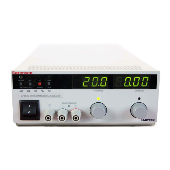
- Page 1 Internal GPIB Interface for XHR/XFR Series Programmable DC Power Supplies Operation Manual GPIB-XHR GPIB -XFR GPIB -XFR3 TM-GPRF-01XN Rev B www.programmablepower.com...
- Page 3 About AMETEK AMETEK Programmable Power, Inc., a Division of AMETEK, Inc., is a global leader in the design and manufacture of precision, programmable power supplies for R&D, test and measurement, process control, power bus simulation and power conditioning applications across diverse industrial segments.
- Page 4 This page intentionally left blank.
- Page 5 Neither AMETEK Programmable Power Inc., San Diego, California, USA, nor any of the subsidiary sales organizations can accept any responsibility for personnel, material or inconsequential injury, loss or damage that results from improper use of the equipment and accessories.
- Page 6 This page intentionally left blank.
- Page 7 AMETEK will, at its expense, deliver the repaired or replaced Product or parts to the Buyer. Any warranty of AMETEK will not apply if the Buyer is in default under the Purchase Order Agreement or where the Product or any part...
- Page 8 This page intentionally left blank.
-
Page 9: Table Of Contents
Contents Section 1. Description ............7 Features and Features and Functions . - Page 10 Contents Accumulated Status, Status, and Fault Registers ......46 Error Codes ............47 Troubleshooting .
-
Page 11: Description
Section 1. Features and Specifications Description The internal GPIB interface card allows you to operate your power supply from a computer controller via the IEEE-488 communications bus. See Figure 1.1, “Sample Configuration using GPIB Interface”. The GPIB interface allows complete remote programming of your power supply, including status reporting, settings query, and interrupt generation with user-designated fault conditions. -
Page 12: Features
Features and Specifications Features and Functions Features and Functions • Features 16-bit programming and readback of voltage and current • Programmable soft limits for voltage and current • Programmable over voltage protection with reset • Easy-to-use, self-documenting command set • Isolated user-programmable signals such as fault, polarity, isolation, and auxiliary signals •... -
Page 13: Specifications
Features and Specifications Specifications Specifications The specifications in this section are warranted at 25°C ±5°C unless otherwise specified. All specifications are subject to change without notice. Table 1.1 Specifications for XFR 1200 W Series Supply with GPIB Interface Installed (7.5 V to 40 V) Models 7.5-140 12-100... - Page 14 Features and Specifications Specifications Table 1.2 Specifications for XFR 1200 W Series Supply with GPIB Interface Installed (60 V to 600 V) Models 60-20 100-12 150-8 300-4 600-2 Program Resolution Voltage 9.2mV 15.4mV 23.1mV 46.2mV 92.4mV Current 2.8mA 1.68mA 1.12mA 0.56mA 0.28mA 9.2mV...
- Page 15 Features and Specifications Specifications Table 1.3 Specifications for XFR 2800 W Series Supply with GPIB Interface Installed (7.5 V to 40 V) Models 7.5-300 12-220 20-130 33-85 40-70 Program Resolution Voltage 1.16mV 1.8mV 3.08mV 5.1mV 6.2mV Current 42.0mA 30.8mA 18.2mA 13.0mA 9.8mA 1.16mV...
- Page 16 Features and Specifications Specifications Table 1.4 Specifications for XFR 2800 W Series Supply with GPIB Interface Installed (60 V to 600 V) Models 60-46 100-28 150-18 300-9 600-4 Program Resolution Voltage 9.2mV 15.4mV 23.1mV 46.2mV 92.4mV Current 6.44mA 3.92mA 2.52mA 1.26mA 0.56mA 9.2mV...
- Page 17 Features and Specifications Specifications Table 1.5 Specifications for XHR 1000 W Series Supply with GPIB Interface Installed (7.5 V to 60 V) Models 7.5-130 20-50 33-33 40-25 60-18 Program Resolution Voltage 1.16mV 1.8mV 3.08mV 6.2mV 9.2mV Current 42.0mA 30.8mA 18.2mA 9.8mA 6.44mA 1.16mV...
- Page 18 Features and Specifications Specifications Table 1.6 Specifications for XHR 1000 W Series Supply with GPIB Interface Installed (100 V to 600 V) Models 100-10 150-7 300-3.5 600-1.7 Program Resolution Voltage 15.4mV 23.1mV 46.2mV 92.4mV Current 3.92mA 2.52mA 1.26mA 0.56mA 15.4mV 23.1mV 46.2mV 92.4mV...
-
Page 19: Introduction
Section 2. Installation and Configuration Introduction To use this product, you must have the following equipment: • a compatible model of DC output power supply • IEEE-488 connector and cable • computer with an IEEE-488 interface • Computer-based communications software package We usually install the GPIB interface in a power supply at the factory. - Page 20 Installation and Configuration Initial Inspection CAUTION Use proper static control techniques to avoid damage to static-sensitive components on the printed circuit board. Remote LED (REM) Local Switch (LOCAL) Remote Programming LEDs: Address LED (ADR) Fault LED (FLT) Indicates that the master controller is addressing the unit. Indicates that a fault has occurred.
- Page 21 Installation and Configuration Initial Inspection Error LED (ERR) Indicates that a programming error has occurred. Clear with the error query command. Address LED (ADR) Indicates that the unit is being addressed by the master controller. IEEE 488 Connector SW1 Switch) Switch Position Reference 1 Remote/Local Startup Markings (0) (1)
- Page 22 Installation and Configuration Initial Inspection JUMPER SELECTION Local OVP control selection [closed] [default]. See page 24. [open] Front Panel OVP Control. User TTL shutdown (S/D) selection [1-2] User TTL S/D line active low. See page 27. [2-3] [default] User TTL S/D line active high. J103 Remote OVP Control Selection [closed] [default].
-
Page 23: Basic Setup Procedure
Installation and Configuration Basic Setup Procedure Basic Setup Procedure This procedure can be used as a quick reference for those familiar with the configuration requirements for the GPIB interface as installed in the DC power supply. For those who want more information, each step refers to more detailed procedures located in subsequent sections. -
Page 24: Ieee-488 Primary Address Selection
Installation and Configuration IEEE-488 Primary Address Selection IEEE-488 Primary Address Selection 1. Assign a primary address to each power supply: Choose a number between 0 and 30 which is unique to your IEEE-488 bus, that is, different from other device addresses on the same bus. -
Page 25: Power On Service Request (Pon Srq)
Installation and Configuration Power On Service Request (PON SRQ) Power On Service Request (PON SRQ) The Power ON Service Request (SRQ) switch is located on the GPIB subplate rear panel S1 switch. Enabling the SRQ switch causes the power supply to send a service request to the computer controller when the power supply is turned on or when it re-initializes after a momentary power interrupt. -
Page 26: Remote Mode Operation
Installation and Configuration Remote/Local Operation If the rear panel PON REM switch is set to 1, the power supply will power up in local mode. Power supply control is at the front panel. During an operating session, you can toggle between local mode and remote mode by using the front panel LOCAL button and sending commands as described in “Remote Mode Operation”... -
Page 27: Local Mode Operation
Installation and Configuration Remote/Local Operation While in remote mode, you can change to local mode operation by pressing the front panel LOCAL button, by sending the GPIB GTL (Go to Local) command, or by negating the GPIB REN (Remote Enable) line. You can disable the LOCAL button by enabling the GPIB Local Lockout (LLO) condition. -
Page 28: Ieee-488 Controller Connection
Installation and Configuration IEEE-488 Controller Connection ibfind GPIB0 Address the computer controller ibcmd "?_@\x11" Send commands (UNL, UNT, MTA0, LLO) in ASCII. ibfind "devname" Address the unit (devname or device name as configured originally with ibconf). ibloc Set unit to local mode. Note: To disable Local Lockout, use the IBIC ibsre0 command in this example. -
Page 29: Ttl Shutdown
Installation and Configuration Internal PCB Jumper Selections Control Mode Selection” shows a table of jumper settings and OVP programming selection. Refer to “Basic Setup Procedure” on page 19 for the positions of the jumpers on the GPIB PCB. Table 2.6 OVP Control Mode Selection PCB Jumper PCB Jumper OVP Programming Selection... -
Page 30: User Signals
Installation and Configuration User Signals User Signals Connector J7 Auxiliary connector J7, located on the GPIB interface rear panel, provides several User Signals signals to increase your operating control of the supply. These signals are dependent on the operator's design and uses. The operation of the J7 signal requires that you provide external Vcc and ground. -
Page 31: J7 Cable Connection
Installation and Configuration User Signals Figure 2.5 J7 User Signal Connector Circuit Block Diagram J7 Cable Use a standard 8-position telephone jack and data cable to connect to J7. Add a ferrite block to reduce radiated emission. The one inch square ferrite block with Connection built-in housing clip is packaged and shipped with the power supply interface card. - Page 32 Installation and Configuration User Signals J7 User Cable Ferrite Block To J7 Connector To User Custom Interface Figure 2.6 J7 User Cable with Ferrite Block Operating Manual for GPIB for XHR/XFR Series Power Supply...
-
Page 33: Introduction
Section 3. Operation Introduction This section covers GPIB interface programming, starting with IEEE-488 functions, continuing with an extensive set of device-dependent commands, and, finally, providing error codes, and status and fault register information. GPIB Operation A GPIB interface controller card enables you to control an IEEE-488 bus system via computer, identifying which of its interconnected devices are to send and receive data. -
Page 34: Multiline Control Functions
Operation GPIB Operation Table 3.1 IEEE-488.1 Interface Functions Implemented Mnemonic Capability Description Source Handshake Device must properly transfer a multiline message. Multiline Acceptor Handshake Device must properly receive remote multiline Control messages. Functions Talker Device must be able to transmit. Listener Device must receive commands and data. -
Page 35: Device Trigger
Operation GPIB Operation Device Device Trigger will implement the most recently programmed values whether the Trigger unit is in local or remote control. If the power supply is in local mode, the new values will be implemented when it is switched from local to remote control. Device Trigger is typically used to synchronize the operation of a number of addressed devices. -
Page 36: Service Request
Operation GPIB Operation Service Service request is a uniline message asserted by the power supply at power on and Request for fault conditions. Ten (10) power supply conditions are defined as faults: CV, CC, OV, OTP, SD, FOLD, ERR, ACF, OPF, and SNSP. See “Accumulated Status, Status, and Fault Registers”... -
Page 37: Command Syntax
Operation Command Syntax Command Syntax Manual The manual uses these conventions when displaying command information. These Conventions characters are not part of the command but are used to denote parameters used with the command. < > (angle brackets) Angle brackets enclose a parameter. Do not include the angle brackets in the command line you send to the computer. - Page 38 Operation Command Syntax • Use commas between parameters in those commands with more than one parameter, and between mnemonic parameters as in the MASK and UNMASK commands. Only one comma is allowed and it may be preceded or followed by any number of spaces.
-
Page 39: Command Strings
Operation Command Syntax Command If you send more than one command line, separate the commands with a semicolon. Strings The semicolon may be preceded or followed by spaces. Example: ISET 2.0A; VSET 5V ISET 2.0A; VSET 5V Command Terminators indicate the end of a command string and tell the power supply to execute the command. -
Page 40: Command Summary
Operation Command Summary Command Summary Use these commands to control the operation of the supply. They are listed here in order of function such as PROGRAMMING, QUERY, CALIBRATION, and STATUS commands. See “Command Reference” on page 39 for more detailed information about each command and its use. - Page 41 Operation Command Summary Table 3.6 Query Commands Command Description AUXA? Asks for the state of the set value for the AUXA command AUXB? Asks for the state of the set value for the AUXB command CMODE? Asks for the power supply’s calibration mode status. DLY? Asks for the programmable time delay setting before the supply reports fault conditions.
- Page 42 Operation Command Summary Table 3.7 Calibration Commands Command Description CMODE Places the supply into calibration mode. IDATA Calculates the slope and intercept for current programming. Sets the current output to the high calibration point. Sets the current output to the low calibration point. IRDAT Calculates the slope and intercept for current readback.
-
Page 43: Command Reference
Operation Command Reference Command Reference Table 3.9 Command Reference Command Description ASTS? Asks for the supply’s accumulated status register. The accumulated status register stores any bit that was entered in the status register since the accumulated status query command (ASTS?) was last used, regardless of whether the condition still exists. - Page 44 Operation Command Reference Command Description DLY <seconds> Sets a programmable time delay employed by the supply before reporting fault conditions. The power supply uses the time delay after receiving a new output voltage or current setting via VSET or ISET, or after receiving RST, TRG, or OUT ON commands.
- Page 45 Operation Command Reference Command Description FOLD? Asks for the supply’s present foldback setting. Response: FOLD <mode> where mode is: 0 (OFF) or 1 (CV or Constant Voltage mode) or 2 (CC or Constant Current mode) HOLD <1/ON>,<0/OFF> Enables or disables voltage/current setting hold mode for the supply. When HOLD ON is specified, hold mode is enabled so that all voltage and current settings which would normally be implemented by the supply are held until a TRG (trigger) command is received.
- Page 46 Operation Command Reference Command Description IRDAT <Ilo>,<Ihi> Calculates and records the slope and offset for readback voltage using IRLO and IRHI data. Set CMODE ON before using this command. See also the calibration procedures in Section 4. <Ilo> and <Ihi> are in <current> format. IRHI The power supply outputs a current value to an external device connected as part of the calibration procedure and records a current readback value...
- Page 47 Operation Command Reference Command Description OVCAL Causes the master controller to perform automatic calibration of the supply’s over voltage protection circuitry. Set CMODE ON before using this command. Ensure jumper J65 on the GPIB Interface PCB is connected for remote operation. OVSET <voltage>...
- Page 48 Operation Command Reference Command Description Implements programmed voltage and current settings which had been in hold mode. The supply operates with previous values until the TRG (trigger) command is sent. UNMASK <mnemonics> Enables you to select the supply operating conditions that you are most interested in monitoring for fault occurrence.
- Page 49 Operation Command Reference Command Description VMAX <voltage> Sets an upper soft limit on the supply’s programmed output voltage. If the soft limit is exceeded, or if the soft limit value is lower than the present output voltage setting, the supply will ignore the command, turn on the ERR LED, and set the ERR bit in the accumulated status register.
-
Page 50: Accumulated Status, Status, And Fault Registers
Operation Accumulated Status, Status, and Fault Registers Accumulated Status, Status, and Fault Registers The GPIB option card uses three separate registers which are always active. They are the accumulated status, status, and fault registers. You can use the status commands shown in Table 3.8, “Status Commands” to activate the registers. The bit register has twelve conditions, each assigned a bit weight. -
Page 51: Error Codes
Operation Error Codes Error Codes If the ERR flag in the accumulated status or fault registers has been activated, an ERR? query will return an error number which corresponds to an event described in the following table. The ERR? query will also clear the ERR bit in the register. Table 3.11 Error Codes ERROR # ERROR IDENTIFICATION EXPLANATION... -
Page 52: Troubleshooting
Operation Troubleshooting Troubleshooting WARNING Exercise caution when using and servicing power supplies. High energy levels can be stored at the output voltage terminals on all power supplies in normal operation. In addition, potentially lethal voltages exist in the power circuit and the output connector of power supplies which are rated at 40V and over. -
Page 53: Introduction
Section 4. Calibration Introduction WARNING Exercise caution when using and servicing power supplies. High energy levels can be stored at the output voltage terminals on all power supplies in normal operation. In addition, potentially lethal voltages exist in the power circuit and the output connector of power supplies which are rated at 40V and over. -
Page 54: Calibration Voltage Mode Calibration
Calibration Voltage Mode Calibration Voltage Mode Calibration Voltage 1. Disconnect the load from the power supply which is to be calibrated. Calibration 2. Connect a voltmeter across the power supply’s output terminals. Setup Power Supply Power Supply Positive Output Negative Output VOLTMETER Figure 4.1 Voltage Calibration Setup Voltage... - Page 55 Calibration Voltage Mode Calibration 3. Send command VRLO; IRLO to the power supply. Wait for the supply to settle. Measure and record the output shown on the external voltmeter. Send VRLO again. 4. Send VRHI; IRHI to the supply. Wait for the supply to settle. Measure and record the output voltage shown on the external voltmeter.
-
Page 56: Current Mode Calibration
Calibration Current Mode Calibration Current Mode Calibration Current 1. Disconnect the load from the power supply to be calibrated. Calibration 2. Connect a shunt across the supply's output terminals. Setup 3. Connect a voltmeter across the shunt. Power Supply Power Supply Positive Output Negative Output Current Sensing... -
Page 57: Current Readback Calibration Procedure
Calibration Current Mode Calibration Current 1. Connect the current shunt and voltmeter to the power supply as shown in Readback Figure 4.2. Calibration 2. Activate calibration mode by sending command CMODE ON or CMODE 1 to Procedure the power supply. 3. -
Page 58: Over Voltage Protection (Ovp) Calibration
Calibration Over Voltage Protection (OVP) Calibration Over Voltage Protection (OVP) Calibration We recommend that you perform OVP calibration every six months. Connecting a digital voltmeter as in “Voltage Calibration Setup” is optional. 1. Disconnect all loads from the power supply. 2.
Need help?
Do you have a question about the Sorensen GPIB-XHR and is the answer not in the manual?
Questions and answers