
Related Manuals for Metasys MULTI SYSTEM 1


Summary of Contents for Metasys MULTI SYSTEM 1
- Page 1 MULTI SYSTEM TYP 1 Instructi ons for use EN | ZK-58.203/00 | 2021-09 eIFU: www.metasys.com/downloads...
-
Page 2: Table Of Contents
Table of contents Table of contents Notes ..............................4 1.1. General instructions ..........................................4 1.2. Explanation of the symbols ......................................... 4 1.3. Copyright notice ..........................................5 Intended use ............................6 2.1. Indication ............................................. 6 2.2. Contraindication ..........................................6 2.3. Target group ............................................6 Safety-related information .........................7 3.1. - Page 3 ZK-58.203/00 If you would like to request a printed copy of the instructions for use, please contact us at ifu@metasys.com or use the order form at www.metasys.com/downloads A hardcopy of the instructions for use will be made available to you free of charge and within seven calendar days of receipt of the request.
-
Page 4: Notes
Notes 1.1. General instructions METASYS can only guarantee the safety, reliability and performance of the dental device if the following instructions are adhered to: > The product is only to be used in accordance with the instructions for use. >... -
Page 5: Copyright Notice
Fault on end device Use hand protection Stacking limit n = (quantity) 1.3. Copyright notice All names and contents are protected by copyright. Distribution, duplication or alternative use of this document is only permitted with the written consent of METASYS Medizintechnik. -
Page 6: Intended Use
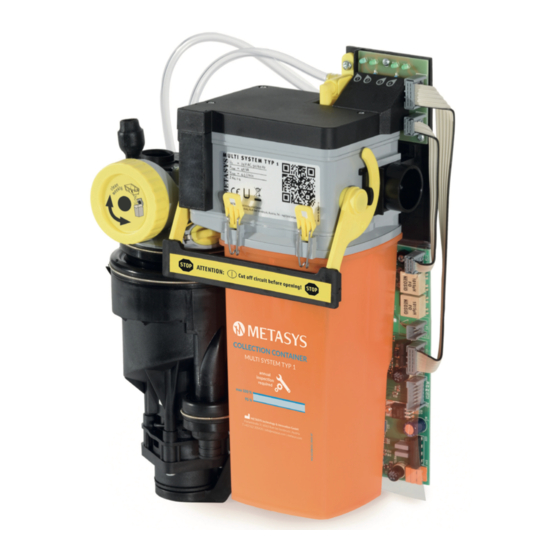
Intended use Intended use The MULTI SYSTEM TYP 1 is a two-stage, single unit amalgam separator with integrated air/water separation and place selection valve for separating amalgam from waste water from dental treatment units. 2.1. Indication Not applicable. 2.2. Contraindication Not applicable. -
Page 7: Safety-Related Information
Safety-related information Safety-related information 3.1. General safety-related information All serious incidents related to the device must be reported to the manufacturer and the competent authority of the Member State where the user and/or the patient is resident. 3.2. Safety instructions Assembly, modifications or repairs may only be carried out by authorised qualified personnel who guarantee compliance with the EN 60601-1 standard (international standard on Medical Electrical Equipment and Systems, in particular part 1: General requirements for basic safety). -
Page 8: Product Description
Product description Product description 4.1. Product description MULTI SYSTEM TYP 1 is a two-stage, single unit amalgam separator with integrated, static air/water separation and place selection valve. 4.2. Technical data / performance data Height [H] Width [W] Depth [D] MULTI SYSTEM TYP 1 Power supply 24 V AC Frequency... -
Page 9: Construction
Product description Device description Connection data Registration number Deutsches Institut für Bautechnik (DIBT) (German Institute of Construction Technology) Mark of conformity per para. 22 section 4 Lower Saxony Building Regs Separate collection of electrical/electronic equipment (WEEE) Follow instructions for use Date of manufacture Serial number Manufacturer... - Page 10 Product description Place selection valve Module 2 (air/water separation) Exhaust air to suction motor Collection container Pump motor Centrifuge Spittoon waste water input Waste water output Pump...
-
Page 11: Preparation For Use
Preparation for use Preparation for use 5.1. Transport and storage The device is shipped in two polystyrene shells fi xed together. This original packaging must be used for any onward and return transport. The device must always be transported and stored in an upright position. The device must be transported to the installation site in a completely packed state. After unpacking the device, check for completeness and possible transport damage. 70 °C Transport and storage temperature 0 °C... -
Page 12: Pipe And Hose Connections
Preparation for use Installation in the behind the patient‘ head If there is no spittoon at the treatment chair and the suction system is located behind the head of the patient, the device can be installed inside a cabinet. In this case, the connection opening for the spittoon drain must be closed with a blind plug. Split version For work places which have suction behind the patients’... -
Page 13: Connection Dimensions
Preparation for use Water jet operated saliva ejectors must be shut down due to high water consumption. The fl ushing of the spittoon must be limited by means of a timer or button to max. 30 seconds at a max. water fl ow of 3 l/min to enable the centrifuge to stop. For matching hose nozzles and adapters see 9.1.1. Accessories, service kits, collection containers and spare parts. 5.2.3. Connection dimensions ø... - Page 14 Preparation for use Check the coarse sieve in the spittoon Install the pre-filter (if not present in the hose storage) MULTI SYSTEM TYP 1 Built-in version Fit a contact protection plate behind module 1 (if the subsurface is electrically conductive) Connect the spittoon drain hose Connect the drain hose Connect the suction line from the hose storage (suction hose) and to the suction machine (suction hose) MULTI SYSTEM TYP 1 with cover...
-
Page 15: Installation And Assembly Of Optional Accessories, Retrofit Parts And Spare Parts
Praxisstempel & Unterschrift Dental Surgery Stamp & Signature installation@metasys.com Fax: +43 512 205420-1123 METASYS Medizintechnik GmbH | Florianistraße 3, 6063 Rum bei Innsbruck, Austria | Phone: +43 512 205420 | info@metasys.com | www.metasys.com Carry out a normal operation test see 7.2.3. Normal operation test 5.3.1. -
Page 16: Connecting To Other Devices
(maximum 1/4 turn to the left or right). Then carry out the function test (step 3) again. 5.3.2. Connecting to other devices When connecting the METASYS device to other devices or systems, hazards can arise. It must therefore be ensured that no hazards arise for the user or the patient and that the environment is not affected. The specifi cations of the manufacturer of the device or system to be connected must be observed. 5.4. -
Page 17: Electrical Connections
Preparation for use 5.4.1. Electrical connections Main board Diagnostic board Module 2 Module 3 External display Hose storage switch and suction system isolating relay Connector for centrifuge inlet probe Connector for centrifuge motor Connector for power supply (24 V AC) Connector for external display Connection to the diagnostic board (power supply for motor and magnetic valve in module 2) -
Page 18: Use
6.1. Normal operation Ensure that the device is switched off at least 1 x per working day for level measurement. The 24 V AC power supply must be connected after the device’s or practice‘s main switch. 6.2. External and internal displays 6.2.1. -
Page 19: Error Messages
Assembly, modifi cations and repairs may only be carried out exclusively by authorised specialist personnel (see 3.2. Safety instructions)! The METASYS technical customer service is also available for further information and assistance in carrying out repairs, retrofi tting, fault analyses, etc. -
Page 20: Care And Maintenance
Care and maintenance Care and maintenance 7.1. Regular cleaning measures For trouble-free operation, briefly flush the spittoon after each treatment, and flush each suction hose with cold water to remove residues from the lines. The following cleaning measures must be carried out regularly: Measure Interval Cleaning and disinfection of the suction 2 x daily see 7.1.1. Daily cleaning with GREEN&CLEAN M2 system Empty and clean the filter drawer At least 1 x per week, depending on workload, Remove, empty and clean the filter drawer. -
Page 21: Maintenance And Service
Carefully push module 2 back into the holder and close the locking bracket. Switch on the main switch. 7.2. Maintenance and service Assembly, modifi cations and repairs may only be carried out exclusively by authorised specialist personnel (see 3.2. Safety instructions)! For further information and assistance in carrying out repairs, retrofi tting, fault analyses, etc., the METASYS technical customer service is also available! Warning: Switch off the main switch of the treatment unit! Warning:... - Page 22 Care and maintenance Tilt the locking bracket on module 2 upwards, remove it and place it on a fl at, non-slip surface. Open the 4 yellow clip fasteners on module 2, hold the collection container and lift off the upper part. If the pump sieve (1) is dirty, pull it off, clean it over a collection receptacle and put it back on the suction housing of the pump.
-
Page 23: Disposal Of The Collection Container
GERMANY T +49 8823 938 44 33 For disposal using DENTAL ECO SERVICE: entsorgung@metasys.com AUSTRIA T +43 512 205420 entsorgung@metasys.com Empfänger / Consignee Visit www.metasys.com/collection_centers for more information on disposal in your country! For other countries please visit: www.metasys.com/collection_centers... -
Page 24: Normal Operation Test
Care and maintenance Stopping residues, sieve residues or other waste containing amalgam must be collected in a suitable container and can be disposed of by a disposal company (e.g. DENTAL ECO SERVICE). 7.2.3. Normal operation test The normal operation test checks the operating functions of the device. This test should be carried out after installation as well as after every repair! Switching on the main switch: LED 1 on the external display lights up green. -
Page 25: 1-Year Service Kit
According to the Deutsches Institut für Bautechnik (German Institute for Construction Technology), the display units of amalgam separators must be checked for function at least once a year by an expert! METASYS makes it mandatory to carry out the 1-year inspection. The 1-year inspection must be entered in the device document! Check LED 1 (“Ready for operation”) -
Page 26: 5-Year Service Kit
Care and maintenance Check LED 3 (“Level indicator”) Switch off the main switch Take out module 2 Unplug centrifuge connector SV2 on the main board (1) On the main board, cover the lower diode of the light barrier (2) Switch on the main switch (3) LED 3 lights up yellow: Buzzer sounds (switchable via RESET) Switch off the main switch... -
Page 27: Replacement Of Module 2
Care and maintenance Pull down the centrifuge support and detach the centrifuge cover from the centrifuge (do not remove the centrifuge inlet seal!) Swing out the centrifuge. Pull off the centrifuge flange cap (1). Loosen the 4 fastening screws on the centrifuge flange (2) and remove the flange. Remove both centrifuge inner parts (3) upwards. Separate the inner and outer centrifuge chambers. Hold each centrifuge chamber individually against a light source and visually check for contamination;... -
Page 28: Replacement Of Inlet Main Body
Care and maintenance Loosen the screws (3 pieces) on the cover Remove the cover Loosen the hand nut on the magnetic valve Pull out the magnetic valve Remove the connection cable from the connector strip Insert new magnetic valve and connect connection cable to connector strip Fasten magnetic valve with hand nut Put on cover and fasten with screws (3 pieces) Carefully push module 2 back into the holder and close the locking bracket... -
Page 29: Decommissioning
Risk of contamination: To avoid infection, wear personal protective equipment (hand, eye, nose and mouth protection) and disinfect and clean the device! If it is necessary to return the device to the depot or to METASYS, the original METASYS packaging must be used. Before packing the METASYS device to be transported, clean and disinfect it. Possible openings where residual fl uids could escape must be closed. -
Page 30: Annex
Annex Annex 9.1. REF numbers and scope of delivery Designation Scope of delivery 01010001 MULTI SYSTEM TYP 1 Amalgam separator with standard accessories and instructions for use 01010003 MULTI SYSTEM TYP 1 - KaVo Amalgam separator with KaVo accessories and instructions for use 01010005 MULTI SYSTEM TYP 1 - Ultradent Amalgam separator with Ultradent accessories and instructions for use... - Page 31 Annex Order number Designation Order number Designation 55020001-AT Exchange container MST 1, AT, Austria, with 55020001-HU Exchange container MST 1 HU, Hungary postage 55020001-AU Exchange container MST 1 AU, Australia 55020001-IT Exchange container MST 1 IT, Italy 55020001-CH Exchange container MST 1 CH, Switzerland, 55020001-NO Exchange container MST 1 NO, Norway with postage...
- Page 32 Tube nozzle, 15 mm, 90°, 5 pcs. 40010100 Adapter, 15/18 mm, O-ring, 2 pcs. 40010012 Angle-piece water outlet, 15 mm 40010102 Adapter, for METASYS, female 40010015 Double nozzle, 22-25 mm 40010103 Lock clip, adapter 40010017 Extension air duct, 72.5 mm...
- Page 33 Adapter, META Connect, Dürr Connect large, 36 mm 40010079 Adapter, 25 mm, mini-nozzles 40010125 Adapter, META Connect, 32 mm 40010084 Adapter, für METASYS, male 40010126 Adapter, META Connect, 36 mm 40010085 Adapter, 45°, with air duct 40010127 Adapter, META Connect, 50/40 mm...
- Page 34 Annex Module 1 50020001 50020048 50020006 50110003 50110004 50120003 50120002 50020062 50020007 50020046 50020032 50020051 50020034 40050030 50020024 50020018 50020028 50110012 50020031 50110013 55010002 50020014 50020019...
- Page 35 Annex Module 2 50110001 50110001 50020025 50020025 50020015 50020002 55020001 50020023 50020047 50020016 50120004 50110005 50020005 50020041 50020027 55010005 50020022...
- Page 36 Annex Module 3 50110010 50020043 50020035 50020017 50020003 50020026 50110011 Cover External display 50020004 50020042 40050029 50020050 40500001 50020020 50020045 50020044 40050026 Hose nozzles and adapters META Connect ø 21 ø 26 ø 26 ø 26 ø 26 ø 26 ø...
- Page 37 Annex Hose nozzles and adapters META Connect ø 22 ø 26 ø 22 ø 26 ø 22 ø 22 ø 26 ø 26 ø 22 ø 26 ø 26 ø 31 ø 26 ø 22 ø 22 ø 22 ø 22 ø...
-
Page 38: Warranty Conditions
ø 20 ø 16 ø 16 ø 16 ø 16 ø 16 ø 16 40010089 40010090 40010091 40010097 40010098 40010099 ø 25 ø 18 ø 19 ø 28 ø 26 ø 15 40010100 40010105 9.2. Warranty conditions METASYS grants a guarantee of 12-36 months for specifi c products (duration of guarantee depends on the product according to the information in the current... -
Page 39: Change History
The customer sends the device or component in question to METASYS at his own expense. METASYS checks whether there is a warranty claim. METASYS will repair the device or component if it is cost-effective. The customer is charged for the costs incurred for the repair, but not the replacement parts covered by the guarantee. - Page 40 METASYS Medizintechnik GmbH Florianistraße 3 | 6063 Rum bei Innsbruck | Austria Subject to printing and setting errors! T +43 512 205420 | info@metasys.com | metasys.com...
Need help?
Do you have a question about the MULTI SYSTEM 1 and is the answer not in the manual?
Questions and answers