Table of Contents
Advertisement
Advertisement
Table of Contents

Subscribe to Our Youtube Channel
Related Manuals for Husqvarna EE 5 2022


Summary of Contents for Husqvarna EE 5 2022
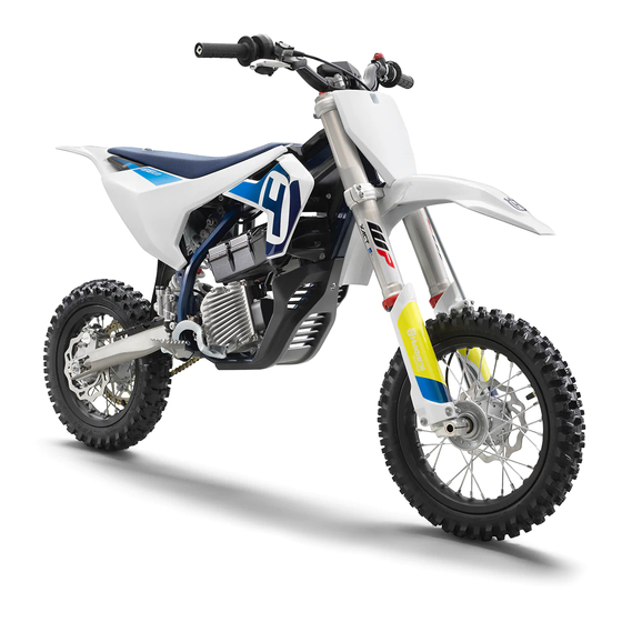
- Page 1 OWNER'S MANUAL 2022 EE 5 Art. no. 3402528en...
- Page 3 DEAR HUSQVARNA MOTORCYCLES CUSTOMER Congratulations on your decision to purchase a Husqvarna motorcycle. You are now the owner of a state-of- DEAR HUSQVARNA MOTORCYCLES CUSTOMER the-art sports vehicle that will continue to give you and your child pleasure for a long time if you maintain it properly.
-
Page 4: Table Of Contents
TABLE OF CONTENTS TABLE OF CONTENTS MULTIFUNCTIONAL ELEMENT ...... 19 MEANS OF REPRESENTATION......5 Multifunctional element....... 19 Symbols used ........5 Ride mode button ....... 19 Formats used ........5 Ride mode display ......20 SAFETY ADVICE ..........6 Malfunction indicator lamp ....20 Use definition –... - Page 5 TABLE OF CONTENTS 11.14 Adjusting the rebound damping of BRAKE SYSTEM ..........62 the fork..........38 14.1 Checking play of handbrake lever ..62 11.15 Handlebar position......38 14.2 Adjusting the play of the hand brake 11.16 Adjusting the handlebar position ..
- Page 6 TABLE OF CONTENTS 21.3 Electrical system......... 94 21.4 Tires ............ 94 21.5 Fork............. 94 21.6 Shock absorber ........95 21.7 Chassis tightening torques ....95 SUBSTANCES..........98 AUXILIARY SUBSTANCES......99 STANDARDS ..........100 INDEX OF SPECIAL TERMS ......101 LIST OF ABBREVIATIONS ......102 LIST OF SYMBOLS ........
-
Page 7: Means Of Representation 1
MEANS OF REPRESENTATION 1 Symbols used The meaning of specific symbols is described below. Indicates an expected reaction (e.g., of a work step or a function). Indicates an unexpected reaction (e.g., of a work step or a function). All work marked with this symbol requires specialist knowledge and technical understanding. In the interest of the safety of your child, have these jobs performed in an authorized Husq- varna Motorcycles workshop. -
Page 8: Safety Advice
2 SAFETY ADVICE Use definition – intended use This vehicle is designed and constructed to withstand the stresses and strains of regular racing if the maximum rider weight is not exceeded. Info Only operate this vehicle in closed-off areas remote from public road traffic. Only use the lithium-ion battery while it is inside the vehicle. -
Page 9: Safe Operation
SAFETY ADVICE 2 Opening the rechargeable lithium-ion battery (Powerpack LV) or the motor. Using the vehicle or the rechargeable lithium-ion battery when proper maintenance has not been performed. Using the vehicle or the rechargeable lithium-ion battery outside of its defined use. Using a damaged lithium-ion battery. -
Page 10: Fall Or Accident
When disposing of the lithium-ion battery (Powerpack LV), observe the relevant laws and guidelines of your country. Your authorized Husqvarna Motorcycles dealer can dispose of the Powerpack LV free of charge and in an envi- ronmentally compatible manner. Because motorcycles are not subject to the EU regulations governing the disposal of used vehicles, there are no legal regulations that pertain to the disposal of an end-of-life motorcycle. -
Page 11: Owner's Manual
The Owner's Manual can be downloaded several times using the QR code or the link on the delivery certificate. The Owner's Manual is also available for download from your authorized Husqvarna Motorcycles dealer and on the Husqvarna Motorcycles website. A printed copy can also be ordered from your authorized Husqvarna Motorcycles dealer. -
Page 12: Important Notes
3 IMPORTANT NOTES Manufacturer warranty, implied warranty The work prescribed in the service schedule must only be carried out in an authorized Husqvarna Motorcy- cles workshop and confirmed in the Husqvarna Motorcycles Dealer.net, as otherwise all warranty claims will be void. Damage or secondary damage caused by tampering with and/or conversions on the vehicle are not covered by the manufacturer warranty. -
Page 13: Power Supply
IMPORTANT NOTES 3 Power supply M01701-10 A rechargeable lithium-ion battery (Powerpack LV) is installed in the vehicle. The Powerpack LV supplies electric motor and multifunctional element with voltage. The Powerpack LV is firmly bolted to the frame and motor. Operation at low temperatures In order to protect the Powerpack LV, the motor control reduces the power at low component temperatures. -
Page 14: View Of Vehicle
4 VIEW OF VEHICLE View of vehicle, front left (example) M01715-10 Hand brake lever ( p. 16) Magnetic switch under the seat ( p. 17) Plug-in stand holder Charging socket... -
Page 15: View Of Vehicle, Rear Right (Example)
VIEW OF VEHICLE 4 View of vehicle, rear right (example) M01716-10 Quick release of seat Multifunctional element ( p. 19) Magnetic switch on handlebar ( p. 16) Throttle grip ( p. 16) Vehicle identification number ( p. 14) On/Off button ( p. -
Page 16: Serial Numbers
5 SERIAL NUMBERS Vehicle identification number The vehicle identification number is stamped on the right side of the steering head. 401945-10 Type label The type label is located on the front frame tube. 402154-10 Motor number The motor number is located on the right side of the motor below the Powerpack LV. -
Page 17: Shock Absorber Article Number
SERIAL NUMBERS 5 Shock absorber article number The shock absorber article number is stamped on the bottom of the shock absorber toward the right-hand side. H01186-10 Battery identification number The battery identification number (BIN) is located on a sticker on the Powerpack LV. M01631-10... -
Page 18: Controls
6 CONTROLS Hand brake lever Hand brake lever is fitted on the right side of the handlebar. The hand brake lever is used to activate the front brake. M01656-10 Throttle grip The throttle grip is fitted on the right side of the handlebar. After activation, the vehicle initially does not react to the throttle grip to prevent accidental acceleration. -
Page 19: Magnetic Switch Under The Seat
CONTROLS 6 Warning Risk of injury If the magnetic switch remains in the holder during a fall, the vehicle is not immediately deacti- vated. – Make sure that the loop of the magnetic switch is securely attached to the user’s protective clothing or wrist so that the magnetic switch is disconnected from the holder in the event of a fall. -
Page 20: Plug-In Stand
6 CONTROLS Plug-in stand The fixture for plug-in stand is located on the frame on the left side of the vehicle. The plug-in stand is used to park the motorcycle. Info Remove the plug-in stand before riding. 402581-10 Diagnostics connector Diagnostics connector is located under the seat. -
Page 21: Multifunctional Element 7
MULTIFUNCTIONAL ELEMENT 7 Multifunctional element The multifunctional element is mounted in front of the seat. Overview of multifunctional element Ride mode button ( p. 19) Ride mode display ( p. 20) Malfunction indicator lamp ( p. 20) Charging level indicator ( p. -
Page 22: Ride Mode Display
7 MULTIFUNCTIONAL ELEMENT Ride mode display Red ride mode displays with the numbers 1, 2, or 3 show the ride mode selected. Six ride modes are available. The ride modes define how the vehicle will respond to operation of the throttle grip. The lowest torque is available in ride mode 1. -
Page 23: Power Reduction
MULTIFUNCTIONAL ELEMENT 7 The last segment lights up in yellow: charging level 20% - 30%. The last segment lights up in red and the driving mode indi- cator flashes red: charging level 10%–20%. The last segment and the driving mode indicator light up in red: charging level 0%–10%. -
Page 24: Preparing For Use
8 PREPARING FOR USE Advice on preparing for first use Warning Danger of accidents A lack of physical and mental readiness on the part of the child poses a major risk. Children often underestimate or fail to recognize dangerous situations. – Your child must already be able to ride a bicycle. - Page 25 Never leave the vehicle unattended. – Protect the vehicle against access by unauthorized persons. – Ensure that the pre-sale inspection work has been carried out by an authorized Husqvarna Motorcycles workshop. You will receive a delivery certificate when the vehicle is handed over. –...
-
Page 26: Riding Instructions
9 RIDING INSTRUCTIONS Checks and maintenance measures when preparing for use Info Before every trip, check the condition of the vehicle and ensure that it is safe to operate. The vehicle must be in perfect technical condition when it is being operated. –... -
Page 27: Starting Off
Danger of accidents A spongy pressure point on the front or rear brake reduces braking efficiency. – Check the brake system and do not allow your child to continue riding until the problem is elimi- nated. (Your authorized Husqvarna Motorcycles workshop will be glad to help.) -
Page 28: Recuperation
9 RIDING INSTRUCTIONS Warning Danger of accidents Moisture and dirt impair the brake system. – Explain to your child that he or she must brake carefully several times to dry out and remove dirt from the brake linings and the brake discs. –... -
Page 29: Transporting
RIDING INSTRUCTIONS 9 Transporting Note Danger of damage The parked vehicle can roll away or fall over. – Park the vehicle on a firm and level surface. Note Fire hazard Hot vehicle components pose a fire hazard and explosion risk. – Do not park the vehicle near to materials which are highly flammable or explosive. –... -
Page 30: 10 Service Schedule
Different service intervals may apply in your country, depending on the local operating conditions. Individual service intervals and scopes may change in the course of technical developments. The most up- to-date service schedule can always be found on Husqvarna Motorcycles Dealer.net. Your authorized Husq- varna Motorcycles dealer will be glad to advise you. -
Page 31: Recommended Work
● Final check: Check the vehicle for safe operation and take a test ride. ○ ● ● ● Read out the fault memory after the test ride using the Husqvarna Motorcycles diagnostics tool. ○ ● ● ● Make a service entry in Husqvarna Motorcycles‑Dealer.net. -
Page 32: 11 Suspension Setting
11 SUSPENSION SETTING 11.1 Checking the basic chassis setting with the rider's weight Info When adjusting the basic chassis setting, first adjust the shock absorber and then the fork. – For optimal motorcycle riding characteristics and to avoid damage to forks, shock absorbers, link fork and frame, the basic settings of the suspension components must match the rider's weight. -
Page 33: Compression Damping Of The Shock Absorber
The shock absorber is filled with highly compressed nitrogen. – Please follow the description provided. (Your authorized Husqvarna Motorcycles workshop will be glad to help.) Info The effect of the low-speed compression adjuster can be seen in slow to normal compression of the shock absorber. -
Page 34: Adjusting The High-Speed Compression Damping Of The Shock Absorber
The shock absorber is filled with highly compressed nitrogen. – Please follow the description provided. (Your authorized Husqvarna Motorcycles workshop will be glad to help.) Info The effect of the high-speed compression adjuster can be seen in fast compression of the shock absorber. -
Page 35: Measuring The Dimension Of The Rear Wheel Unloaded
SUSPENSION SETTING 11 – Turn adjusting screw clockwise up to the last perceptible click. – Turn counterclockwise by the number of clicks correspond- ing to the shock absorber type. Guideline Rebound damping Comfort 17 clicks Standard 15 clicks F02185-10 Sport 13 clicks Info Turn clockwise to increase the damping;... -
Page 36: Checking The Static Sag Of The Shock Absorber
11 SUSPENSION SETTING 11.8 Checking the static sag of the shock absorber – Measure dimension of rear wheel unloaded. ( p. 33) – Hold the motorcycle upright with aid of an assistant. – Measure the distance between rear axle and fixed point again. -
Page 37: Adjusting The Spring Preload Of The Shock Absorber
Risk of injury Parts of the shock absorber will move around if the shock absorber is detached incor- rectly. The shock absorber is filled with highly compressed nitrogen. – Please follow the description provided. (Your authorized Husqvarna Motorcycles workshop will be glad to help.) Preparatory work –... -
Page 38: Adjusting The Riding Sag
11 SUSPENSION SETTING 11.11 Adjusting the riding sag Preparatory work – Raise the motorcycle with a lift stand. ( p. 45) – Remove the shock absorber. p. 54) – After removing the shock absorber, clean it thoroughly. Main work – Choose and mount a suitable spring. -
Page 39: Adjusting The Fork Air Pressure
SUSPENSION SETTING 11 11.13 Adjusting the fork air pressure Warning Danger of accidents Modifications to the suspension setting may seriously alter the handling charac- teristic. Extreme modifications to the suspension setting may cause a serious deterioration in the handling characteristic and overload components. –... -
Page 40: Adjusting The Rebound Damping Of The Fork
11 SUSPENSION SETTING When disconnecting, excess pressure will escape from the hose – the fork leg itself does not lose any air. The fork airpump indicator switches off automatically after 80 seconds. – Mount the protection cap. Info Only mount the protection cap by hand. Finishing work –... -
Page 41: Adjusting The Handlebar Position
SUSPENSION SETTING 11 11.16 Adjusting the handlebar position Warning Danger of accidents A repaired handlebar poses a safety risk. If the handlebar is bent or straightened, the material becomes fatigued. The handlebar may break as a result. – Change the handlebar if the handlebar is damaged or bent. –... -
Page 42: 12 Seat Height
12 SEAT HEIGHT 12.1 Seat height adjustment options This vehicle offers several options for adjusting the seat height to the rider's height. The seat height can be changed with the mounting position of the fork, shock absorber, and frame. Info When adjusting the seat height on the fork and shock absorber, make sure that the vehicle is as straight as pos- sible after completion of the work. -
Page 43: Adjusting The Seat Height On The Fork
SEAT HEIGHT 12 12.3 Adjusting the seat height on the fork Warning Danger of accidents Modifications to the suspension setting may seriously alter the handling charac- teristic. – Make sure your child rides slowly to start with after making adjustments in order that he or she can assess the new handling characteristic. -
Page 44: Adjusting The Seat Height On The Frame
12 SEAT HEIGHT 12.4 Adjusting the seat height on the frame Preparatory work – Remove the seat. ( p. 55) Main work – Remove screw M01708-10 – Pull off the front fairing sideways on both sides and remove it upward. M01709-10 –... - Page 45 SEAT HEIGHT 12 – Remove screws and position subframe at the drill holes at the desired seat height. Guideline Pay attention to the wiring harness. High seat position Drill holes Low seat position Drill holes – Mount and tighten screws Guideline Screw, sub- 30 Nm (22.1 lbf ft)
- Page 46 12 SEAT HEIGHT – Position the front fairing on holders M01717-10 – Engage the front fairing on both sides. M01709-11 – Mount and tighten screw Guideline Remaining screws, 10 Nm (7.4 lbf ft) chassis M01708-10 Finishing work – Mount the seat. ( p.
-
Page 47: Service Work On The Chassis 13
SERVICE WORK ON THE CHASSIS 13 13.1 Raising the motorcycle with a lift stand Note Danger of damage The parked vehicle can roll away or fall over. – Park the vehicle on a firm and level surface. – Raise the motorcycle at the frame underneath the engine. Lift stand (78929955100) Neither wheel is in contact with the ground. -
Page 48: Cleaning The Dust Boots Of The Fork Legs
13 SERVICE WORK ON THE CHASSIS 13.4 Cleaning the dust boots of the fork legs Preparatory work – Raise the motorcycle with a lift stand. ( p. 45) – Remove the fork protector. ( p. 46) Main work – Push dust boots of both fork legs downward. -
Page 49: Installing The Fork Protector
SERVICE WORK ON THE CHASSIS 13 13.6 Installing the fork protector – Position the fork protector on the left and right fork leg. Mount and tighten screws Guideline Remaining screws, 10 Nm (7.4 lbf ft) chassis – Position the brake line and the clamp. Mount and tighten screws Guideline M01710-11... -
Page 50: Removing The Lower Triple Clamp
13 SERVICE WORK ON THE CHASSIS Bleeder screws are positioned toward the rear. The second milled groove (from the top) is flush with the upper edge of the upper triple clamp. – Tighten screws Guideline Screw, top triple 20 Nm (14.8 lbf ft) clamp –... -
Page 51: Installing The Lower Triple Clamp
SERVICE WORK ON THE CHASSIS 13 Info Cover the components to protect them against dam- age. Do not kink the cables and lines. – Remove protective ring – Remove the lower triple clamp with the steering stem. – Remove the upper steering head bearing. M01668-10 13.10 Installing the lower triple clamp... - Page 52 13 SERVICE WORK ON THE CHASSIS – Position the upper triple clamp with the handlebar. – Mount nut , but do not tighten it yet. M01714-11 Condition Individual installation position – Position the fork legs. Guideline Observe the position determined during removal. Bleeder screws are positioned toward the rear.
-
Page 53: Checking The Steering Head Bearing Play
Danger of accidents Incorrect steering head bearing play impairs the handling characteristic and damages components. – Correct incorrect steering head bearing play immediately. (Your authorized Husqvarna Motorcy- cles workshop will be glad to help.) Info If the vehicle is operated for a lengthy period with play in the steering head bearing, the bearings and the bearing seats in the frame can become damaged over time. -
Page 54: Adjusting The Steering Head Bearing Play
13 SERVICE WORK ON THE CHASSIS It must be possible to move the handlebar easily over the entire steering range. There should be no detectable detent positions. » If detent positions are detected: – Adjust the steering head bearing play. p. -
Page 55: Removing The Start Number Plate
SERVICE WORK ON THE CHASSIS 13 13.14 Removing the start number plate – Remove screw – Unhook the start number plate from the brake line and remove it. M01719-10 13.15 Installing the start number plate – Attach the start number plate to the brake line. –... -
Page 56: Installing Front Fender
13 SERVICE WORK ON THE CHASSIS 13.17 Installing front fender – Position the fender with drill holes in the holding lugs on the start number plate. M01723-10 – Position front fender. Mount and tighten screws Guideline Screw, fender 6 Nm (4.4 lbf ft) M01810-11 13.18 Removing the shock absorber... -
Page 57: Removing The Seat
SERVICE WORK ON THE CHASSIS 13 Main work – Push splash protector to the side. – Mount the shock absorber with screw Guideline If necessary, observe the installation position noted during removal. Screw, top 45 Nm (33.2 lbf ft) ® Loctite 243™... -
Page 58: Checking The Chain For Dirt
13 SERVICE WORK ON THE CHASSIS 13.22 Checking the chain for dirt – Check the chain for coarse dirt accumulation. » If the chain is very dirty: – Clean the chain. ( p. 56) 400678-01 13.23 Cleaning the chain Warning Danger of accidents Lubricants on the tires reduces the road grip. -
Page 59: Checking The Chain Tension
SERVICE WORK ON THE CHASSIS 13 13.24 Checking the chain tension Warning Danger of accidents Incorrect chain tension damages components and results in accidents. If the chain is tensioned too much, the chain, engine sprocket, rear sprocket, transmission and rear wheel bearings wear more quickly. Some components may break if overloaded. If the chain is too loose, the chain may fall off the engine sprocket or the rear sprocket. -
Page 60: Checking The Chain, Rear Sprocket, Motor Sprocket, And Chain Guide
13 SERVICE WORK ON THE CHASSIS Main work – Loosen nut – Loosen nuts – Adjust the chain tension by turning adjusting screws left and right. Guideline Chain tension 5 … 8 mm (0.2 … 0.31 in) Turn the adjusting screws on the left and right so that Q00401-10 the markings on the left and right chain adjusters... - Page 61 SERVICE WORK ON THE CHASSIS 13 – Check the chain sliding guard for wear. » If the ridge is worn down to the level of the main corpus: – Change the chain sliding guard. – Check that the chain sliding guard is firmly seated. »...
-
Page 62: Adjusting The Chain Guide
13 SERVICE WORK ON THE CHASSIS – Check that the chain guide is firmly seated. » If the chain guide is loose: – Tighten the screws on the chain guide. Guideline Remaining 10 Nm (7.4 lbf ft) screws, chassis M01693-01 Finishing work –... -
Page 63: Checking The Link Fork
SERVICE WORK ON THE CHASSIS 13 13.29 Checking the link fork – Check the link fork for damage, cracks, and deformation. » If the link fork shows signs of damage, cracks, or defor- mation: – Change the link fork. Guideline Repairs on the link fork are not permitted. -
Page 64: 14 Brake System
14 BRAKE SYSTEM 14.1 Checking play of handbrake lever Warning Danger of accidents The brake system fails in the event of overheating. If there is no free travel on the hand brake lever, pressure builds up on the front brake circuit. –... -
Page 65: Checking The Brake Discs
Warning Danger of accidents Worn-out brake discs reduce the braking effect. – Make sure that worn-out brake discs are replaced immediately. (Your authorized Husqvarna Motor- cycles workshop will be glad to help.) – Check the front and rear brake disc thickness at multiple... -
Page 66: Checking The Front Brake Fluid Level
Danger of accidents Old brake fluid reduces the braking effect. – Make sure that brake fluid for the front and rear brake is changed in accordance with the service schedule. (Your authorized Husqvarna Motorcycles workshop will be glad to help.) Note Environmental hazard Hazardous substances cause environmental damage. -
Page 67: Adding Front Brake Fluid
Danger of accidents Old brake fluid reduces the braking effect. – Make sure that brake fluid for the front and rear brake is changed in accordance with the service schedule. (Your authorized Husqvarna Motorcycles workshop will be glad to help.) Note Environmental hazard Hazardous substances cause environmental damage. -
Page 68: Checking The Front Brake Linings
Checking the front brake linings Warning Danger of accidents Worn-out brake linings reduce the braking effect. – Ensure that worn-out brake linings are replaced immediately. (Your authorized Husqvarna Motorcy- cles workshop will be glad to help.) – Check the brake linings for minimum thickness ≥... - Page 69 Danger of accidents Brake linings which have not been approved alter the braking efficiency. Not all brake linings are tested and approved for Husqvarna motorcycles. The structure and friction coefficient of the brake linings, and thus their brake power, may vary greatly from that of original brake linings.
- Page 70 14 BRAKE SYSTEM – Remove screw – Press back the brake linings by slightly tilting the brake caliper laterally on the brake disc. Carefully pull the brake caliper backward from the brake disc. – Press the brake piston back into the basic position and ensure that brake fluid does not flow out of the brake fluid reservoir, extracting some if necessary.
-
Page 71: Checking The Free Travel Of The Foot Brake Lever
BRAKE SYSTEM 14 – Check the brake fluid level and correct if necessary. Guideline Brake fluid level below 5 mm (0.2 in) reservoir rim Brake fluid DOT 4 / DOT 5.1 ( p. 98) – Position cover with membrane – Mount and tighten screws Q00414-10 Info... -
Page 72: Adjusting The Basic Position Of The Foot Brake Lever
14 BRAKE SYSTEM – Detach the foot brake lever spring. – Loosen nut – Turn push rod accordingly until you have free travel Guideline Free travel of foot brake 3 … 5 mm (0.12 … 0.2 in) lever – Hold push rod and tighten nut –... -
Page 73: Checking The Rear Brake Fluid Level
– Check the brake system and ensure that nobody drives the vehicle before the problem is elimi- nated. (Your authorized Husqvarna Motorcycles workshop will be glad to help.) Warning Danger of accidents Old brake fluid reduces the braking effect. -
Page 74: Checking The Brake Linings Of The Rear Brake
45) 14.14 Checking the brake linings of the rear brake Warning Danger of accidents Worn-out brake linings reduce the braking effect. – Ensure that worn-out brake linings are replaced immediately. (Your authorized Husqvarna Motorcy- cles workshop will be glad to help.) -
Page 75: Changing The Rear Brake Linings
Danger of accidents Brake linings which have not been approved alter the braking efficiency. Not all brake linings are tested and approved for Husqvarna motorcycles. The structure and friction coefficient of the brake linings, and thus their brake power, may vary greatly from that of original brake linings. - Page 76 14 BRAKE SYSTEM Note Environmental hazard Hazardous substances cause environmental damage. – Dispose of oils, grease, cleaning agents, brake fluid etc. properly and in compliance with the appli- cable regulations. Info Never use DOT 5 brake fluid. It is silicone-based and purple in color. Oil seals and brake lines are not designed for DOT 5 brake fluid.
- Page 77 BRAKE SYSTEM 14 – Position the new brake linings. Info Always change the brake linings in pairs. Ensure that the brake linings are correctly positioned in the holding spring. – Position the brake caliper on the brake disc. The brake linings are correctly positioned. F02207-11 –...
-
Page 78: 15 Wheels, Tires
15 WHEELS, TIRES 15.1 Removing the front wheel Preparatory work – Raise the motorcycle with a lift stand. ( p. 45) Main work – Remove screw – Loosen screws M01697-10 Warning Danger of accidents Damaged brake discs reduce the braking effect. –... -
Page 79: Removing The Rear Wheel
WHEELS, TIRES 15 – Check the wheel bearing for damage and wear. » If the wheel bearing is damaged or worn: – Change front wheel bearing. – Clean and grease the contact surfaces of the spacers. Long-life grease ( p. 99) –... -
Page 80: Installing The Rear Wheel
15 WHEELS, TIRES – Pull out wheel spindle far enough to allow the rear wheel to be pushed forward. – Push the rear wheel forward as far as possible. Remove the chain from the rear sprocket. Info Cover the components to protect them against dam- age. -
Page 81: Checking The Tire Condition
Checking the tire condition Info Only mount tires approved and/or recommended by Husqvarna Motorcycles. Other tires could have a negative effect on handling characteristics. The type, condition, and pressure of the tires all have a major impact on the handling characteristic of the motorcycle. -
Page 82: Checking Tire Pressure
Other spokes will become looser as a result. – Check spoke tension regularly, and in particular on a new vehicle. (Your authorized Husqvarna Motorcycles workshop will be glad to help.) - Page 83 WHEELS, TIRES 15 – Strike each spoke briefly using a screwdriver blade. Info The frequency of the sound depends on the spoke length and spoke diameter. If you hear different tone frequencies from different spokes of equal length and diameter, this is an indica- tion of different spoke tensions.
-
Page 84: 16 Powerpack Lv, Battery Charger
16 POWERPACK LV, BATTERY CHARGER 16.1 Overview of battery charger Battery charger Carrying handle Power cord Charging cable M01630-10 16.2 Positioning the battery charger Warning Risk of injury If the battery charger is used incorrectly, its intrinsic safety cannot be guaranteed. The battery charger is only suitable for use with a Powerpack. -
Page 85: Charging The Powerpack Lv
Environmental hazard A lithium-ion battery (Powerpack LV) contains components and elements that are harmful to the environment. – Never throw a Powerpack LV into the household trash. – Dispose of the Powerpack LV properly and in compliance with the applicable regulations. (Your authorized Husqvarna Motorcycles workshop will be glad to help.) - Page 86 16 POWERPACK LV, BATTERY CHARGER Info Do not activate the vehicle while the battery charger is connected to the Powerpack LV. If the vehicle is activated during the charging process, the vehicle switches to the malfunction state. Info If the temperature of the Powerpack LV exceeds the permissible value while it is being charged, the bat- tery charger stops charging.
- Page 87 POWERPACK LV, BATTERY CHARGER 16 – Connect the power plug for the battery charger to the mains connection. Charging starts automatically. The multifunctional element indicates the charging level. – Monitor the charging level of the Powerpack LV on the multifunctional element ( p.
- Page 88 16 POWERPACK LV, BATTERY CHARGER – Check charging socket protection cap » If the charging socket protection cap is dirty: – Clean the charging socket protection cap without water or compressed air. » If the charging socket protection cap is damaged or worn: –...
-
Page 89: Cooling 17
COOLING 17 17.1 Cooling The Powerpack LV and the electric motor are air-cooled. Cooling is effected by the air stream. The lower the speed, the less the cooling effect. Dirty cooling fins also reduce the cooling effect. M01734-10... -
Page 90: 18 Cleaning, Care
18 CLEANING, CARE 18.1 Cleaning the motorcycle Note Material damage Components become damaged or destroyed if a pressure cleaner is used incorrectly. The high pressure forces water into the electrical components, connectors, throttle cables, and bearings, etc. Pressure which is too high causes malfunctions and destroys components. –... - Page 91 CLEANING, CARE 18 – After the motorcycle has cooled down, lubricate all moving parts and pivot points. – Clean the chain. ( p. 56) – Treat bare metal (except for brake discs) with a corrosion inhibitor. Preserving materials for paints, metal and rubber ( p.
-
Page 92: 19 Storage
Store the vehicle in a dry location that is not subject to large fluctuations in temperature. Guideline Ideal storage temperature 10 … 20 °C (50 … 68 °F) Info Husqvarna Motorcycles recommends jacking up the motorcycle. – Raise the motorcycle with a lift stand. ( p. 45) –... -
Page 93: Troubleshooting 20
TROUBLESHOOTING 20 The malfunctions are indicated by malfunction indicator lamp and by acoustic signals that sound at the same time. As a first measure for all malfunctions, switch off the vehi- cle using the On/Off button, wait one minute, and switch it on again. - Page 94 20 TROUBLESHOOTING Faults Possible cause Action – Blink code 73 Malfunction during charging Disconnect the battery charger from the vehicle and mains connection, wait 1 minute, restart the charging process. – Replace the charging cable. – Blink code 83 Transport mode activated Deactivate transport mode.
-
Page 95: Technical Data 21
TECHNICAL DATA 21 21.1 Engine Design Brushless DC motor Nominal power 2 kW (3 hp) Maximum electric power 5 kW (7 hp) Recuperation available in ride mode 3 and 6 Maximum torque depending on ride mode approx. Ride mode 1 6 Nm (4.4 lbf ft) Ride mode 2 9 Nm (6.6 lbf ft) -
Page 96: Electrical System
2.75 - 10 38J TT MAXXIS MAXX CROSS SI MAXXIS MAXX CROSS SI The tires specified represent one of the possible series production tires. Additional information is available in the Service section under: www.husqvarna-motorcycles.com 21.5 Fork Fork article number 07.18.6U.02... -
Page 97: Shock Absorber
TECHNICAL DATA 21 21.6 Shock absorber Shock absorber article number 03.18.7U.02 Shock absorber WP XACT 5735 Low-speed compression damping Comfort 18 clicks Standard 15 clicks Sport 12 clicks High-speed compression damping Comfort 2.5 turns Standard 2 turns Sport 1.5 turns Rebound damping Comfort 17 clicks... - Page 98 21 TECHNICAL DATA Nut, push rod ball joint on foot 10 Nm (7.4 lbf ft) brake cylinder Nut, push rod, foot brake lever 6 Nm (4.4 lbf ft) Rear fairing screw 8 Nm (5.9 lbf ft) Remaining nuts, chassis 10 Nm (7.4 lbf ft) Remaining screws, chassis 10 Nm (7.4 lbf ft) Screw, chain sliding guard...
- Page 99 TECHNICAL DATA 21 Screw, front wheel spindle 40 Nm (29.5 lbf ft) ® Loctite 243™ Screw, handlebar support 40 Nm (29.5 lbf ft) ® Loctite 243™ Screw, top shock absorber 45 Nm (33.2 lbf ft) ® Loctite 243™ Nut, rear wheel spindle M12x1 40 Nm (29.5 lbf ft) Nut, swingarm pivot...
-
Page 100: 22 Substances
22 SUBSTANCES Brake fluid DOT 4 / DOT 5.1 Standard/classification – Guideline – Use only brake fluid that complies with the specified standard (see specifications on the container) and that exhibits the corresponding properties. Recommended supplier Castrol – REACT PERFORMANCE DOT 4 ®... -
Page 101: Auxiliary Substances 23
AUXILIARY SUBSTANCES 23 Chain cleaner Recommended supplier ® MOTOREX – Chain Clean High viscosity grease Recommended supplier ® – LGHB 2 Long-life grease Recommended supplier ® MOTOREX – Bike Grease 2000 Motorcycle cleaner Recommended supplier ® MOTOREX – Moto Clean Off-road chain spray Recommended supplier ®... -
Page 102: 24 Standards
24 STANDARDS The SAE viscosity classes were defined by the Society of Automotive Engineers and are used for classifying oils according to their viscosity. The viscosity describes only one property of oil and says nothing about quality. -
Page 103: Index Of Special Terms 25
INDEX OF SPECIAL TERMS 25 Battery identification number Serial number of the Powerpack; this is linked to the vehicle's identification number... -
Page 104: 26 List Of Abbreviations
26 LIST OF ABBREVIATIONS Art. no. Article number circa compare e.g. for example etc. et cetera i.a. inter alia number poss. possibly... -
Page 105: List Of Symbols 27
LIST OF SYMBOLS 27 27.1 Yellow and orange symbols Yellow and orange symbols indicate an error condition that requires prompt intervention. Active driving aids are also represented by yellow or orange symbols. The malfunction indicator lamp flashes – There is a malfunction in the vehicle electronic sys- tem. - Page 106 PARENTS, YOUNGSTERS & OFF-HIGHWAY MOTORCYCLES l l : t i o f e t © r v i • I i t e s f - •...
-
Page 107: Index
The information contained in this publication is offered for the benefit of those who have an interest in riding off-highway motorcycles. The information has been compiled from publications, interviews and observations of individuals and organizations familiar with the use of off-highway motorcycles. - Page 108 Parents...Be Cautious Riding Off-Highway Motorcycles (OHMs) can be an enjoyable form of outdoor recreation when done properly. With preparation, practice, and parental supervision your youngster can safely develop and expand his or her riding skills. Remember, off-highway motorcycles are not toys. This manual is designed to assist you in the important task of teaching your youngster the safe and responsible use of an off-highway motorcycle.
- Page 110 CONTENTS INTRODUCTION PART 3: Operating Procedures and Practice • Purpose of the Booklet • Important Note to Parents • Learning Area/Riding Area • Other Sources of Information • Getting Used to the Vehicle in Motion PART 1: Determining Your • Let’s Start Riding Youngster’s Readiness to Ride an Off-Highway Motorcycle PART 4: Readiness Checklist...
-
Page 111: Introduction
INTRODUCTION Important Note To Parents Purpose of the Booklet arents, Youngsters and Off-Highway Motorcycles Once your youngster is ready to learn to ride, YOU is designed to assist you in determining if must be familiar with the motorcycle. You will be your youngster is ready to ride off-highway serving as teacher, coach, and safety supervisor motorcycles (OHMs). -
Page 112: Other Sources Of Information
INTRODUCTION Other Sources Of Information In addition to the information provided i n Parents, Youn g st ers and Of f -Hi g hway Motorcycles, there are other sources for obtaining safety information. The owner’s manual provides specific maintenance and operating procedures for your motorcycle. -
Page 113: Readiness Guidelines
DETERMINING YOUR YOUNGSTER'S READINESS PART 1 TO RIDE AN OFF-HIGHWAY MOTORCYCLE he first important decision you will have to Also make sure your youngster can comfortably make concerning your youngster and off- reach and work all the controls. For example, can highway motorcycles (OHMs) is whether your they turn the handlebars all the way to the right youngster is ready to ride. - Page 114 PART 1...
- Page 115 PART 1 Additional signs of physical readiness can OHM is when they demonstrate a safety-conscious be observed in your youngster’s other play attitude and are aware of possible injury from activities. In general, a youngster should be reckless OHM operation. If the youngster has a well-coordinated, having good balance and habit of recklessness or is often involved in accidents agility.
- Page 116 PART 1 what causes accidents and how to avoid them. In Being able to judge distance is another general, a youngster should understand that he or visual skill helpful when operating an OHM. Is she can get hurt as a result of making poor choices. your youngster able to tell how far one object is from another, or which of two objects is closer? VISUAL PERCEPTIONS...
-
Page 117: Steps For Safe And Responsible Ohm Riding
PART 1 Steps For Safe And STEP TWO: Teach Your Youngster Safe and Responsible OHM Riding Proper Riding Techniques Teaching your youngster off-highway motorcy- Once you determine that OHM use is proper cling is a step-by-step process. It begins with safety for your youngster, it is time to prepare yourself as rules and moves to actual riding techniques. -
Page 118: Part 2: Pre-Operating Procedures And Practice
PRE-OPERATING PROCEDURES PART 2 AND PRACTICE Protective Gear And Clothing he nature of off-highway riding demands that your youngster wear proper protective gear. Motorcycle riders should ALWAYS wear a helmet, eye protection, gloves, long pants, a long-sleeved shirt or jacket, and over-the-ankle boots. -
Page 119: Mounting/Dismounting
PART 2 • Elbows bent, slightly out and away from Mounting/Dismounting the body. • Hands on the handlebars. Have your youngster wear safety gear whenever • Knees in toward the tank. getting on a motorcycle. This action will stress the •... -
Page 120: Mastering The Controls
PART 2 and full right. See that this can be done easily. Next have the youngster slide up and back on the seat. Mention that body movement is important. Body movement and shifting weight help to control the motorcycle. (Go through these control exercises with the motorcycle’s engine OFF.) Mastering The Controls Show your youngster how to use each control... - Page 121 PART 2 BRAKES move the throttle to various positions. Practice turning the handlebars and using the throttle at Most small off-highway motorcycles have a the same time. hand lever on the right handlebar which operates the front brake. Most also have a foot pedal on ENGINE STOP SWITCH the right side to operate the rear brake.
- Page 122 PART 2 Have your youngster practice shifting with the SPEED LIMITERS engine off. The shift lever, clutch lever (if equiped), (supervisor control feature) and throttle control work together to move the Some models come equipped with a removable motorcycle. When shifting to first gear from neutral exhaust restrictor, or another feature which reduces the throttle is closed, the clutch lever is squeezed, maximum speed.
-
Page 123: Learning Activities
PART 2 Down Learning Activities 6. The place on which you keep your feet when riding. Here are some activities that your youngster can 7. Protective gear for the feet and ankles. use to help learn about motorcycle parts and controls CROSSWORD PUZZLE Here is a crossword puzzle for your youngster to complete. - Page 124 PART 2 NAME THE MOTORCYCLE PARTS (Typical) Have your youngster write the number of the motorcycle part or control on the correct line for the diagrams shown. (Answer Guide on Page 42) Clutch lever Choke or Starter (kick) Hand brake lever enrichening device Electric starter (if equipped) Foot brake lever or pedal...
- Page 125 PART 2 2. Have your youngster show you how the controls LOCATING THE CONTROLS GAME work. Be sure he or she understands the proper Now that you have shown your youngster the operation of each control. Skilled use of these controls, it is your youngster’s turn to show you.
- Page 126 PART 2 5. Is your youngster wearing the proper protective PRE-RIDE CHECK gear? Is the mounting procedure correct? Before you continue: 6. Has your youngster learned to locate the motor- 1. Have you determined your youngster’s readiness cycle controls without looking at them? Does he to ride an OHM? Do not let your youngster ride or she know how to operate them smoothly? if you have any doubt.
-
Page 127: Part 3: Operating Procedures And Practice
OPERATING PROCEDURES PART 3 AND PRACTICE arefully observe your youngster’s first use of that all off-highway motorcycle users under the motorcycle. Observe his or her readiness your supervision get proper riding instructions. to ride. Only permit your youngster to continue Stress that an OHM is not a toy. - Page 128 PART 3...
-
Page 129: Getting Used To The Vehicle In Motion
PART 3 a later exercise. Explain that opening the throttle Getting Used To The will increase speed and that closing the throttle Vehicle In Motion will decrease speed. Releasing the throttle and applying the brakes will slow the motorcycle. Ask GETTING THE FEEL OF THE BRAKES your youngster to tell you how throttle control and braking affect the motorcycles speed. - Page 130 PART 3 allow smooth shifting. Remind the youngster that the throttle should be closed when shifting gears. Practice this exercise several times until the skill is developed. GETTING THE FEEL OF TURNING With the vehicle stopped and the engine OFF, have your youngster practice the proper turning technique: 1.
- Page 131 PART 3 BEING PREPARED FOR RIDING PRACTICE Be sure to observe all the safety precautions covered in the Introduction and Parts 1 and 2. Double check that the riding area is free from FUEL hazards. Your youngster should wear all the proper Put to "on"...
-
Page 132: Let's Start Riding
PART 3 Let's Start Riding Walk next to the motorcycle when your young- ster first starts riding. You can also let the beginner ride back and forth between you and another adult. Help your youngster with the turns as he or she practices throttle control and braking. - Page 133 PART 3 However, riding too slowly will make balance Have your youngster practice turning in both more difficult. Both brakes should be used together directions at slow speeds. Allow enough room to for smooth stops. The left foot should be placed on make a wide turn.
- Page 134 PART 3...
-
Page 135: Part 4: Readiness Checklist
PART 4 READINESS CHECKLIST his Readiness Checklist is provided to help The best way to utilize the Readiness Checklist is you determine your youngster’s readiness to to read the particular ability, consider the answers to learn to safely operate and control an OHM. There the questions for that ability, and check those abilities is a significant amount of judgment needed in that you determine are present in your youngster. -
Page 136: Visual Perception/Motor/Development
PART 4 VISUAL PERCEPTION/MOTOR DEVELOPMENT Ability Points to Evaluate ✓ 1. Youngster can see with Can youngster see letters and numbers at least as well sufficient clarity. as you? Can youngster distinguish colors? Has youngster demonstrated adequate vision in other activities (riding bicycles, running, sports, or other recreational activities)? 2. - Page 137 PART 4 Ability Points to Evaluate ✓ 5. Youngster can state the distances of Can youngster tell how many feet or yards it is from the house objects in terms of feet, yard, miles. to the road? Can youngster tell how wide a hallway is, or the width of a room? 6.
- Page 138 PART 4 Ability Points to Evaluate ✓ Can youngster describe what may cause injury when doing such things as running, swimming, bicycling, riding in a car? 10. Youngster can concentrate on more Can youngster pick out or describe several items within than one element at a time in solving a picture? a puzzle or problem.
-
Page 139: Physical Development
PART 4 PHYSICAL DEVELOPMENT Ability Points to Evaluate ✓ 1. Youngster can sit comfortably on the Can youngster place his or her feet firmly on the footpegs? motorcycle and reach the controls easily. Do the youngster’s fingers reach comfortably around the handlebars and control levers? How about with the handlebars turned? How about in different seating positions? Can youngster stand (with knees slightly bent) and have a few... - Page 140 PART 4 Ability Points to Evaluate ✓ 3. Youngster is sufficiently coordinated. Can youngster walk a “balance beam” (2" x 4" x 8') flat on floor? Can youngster ride a bicycle, rollerskate or skateboard safely? Can youngster walk on tiptoes for 10 feet? Can youngster jump rope? Can youngster catch a ball with hands rather than with arms?
-
Page 141: Social/Emotional Development
PART 4 SOCIAL/EMOTIONAL DEVELOPMENT Ability Points to Evaluate ✓ 1. Youngster can understand and Does youngster follow rules established at home? follow rules. Do teachers say that the youngster follows rules? Does youngster listen and respond to adult supervision? Does youngster comprehend the importance and seriousness of having rules and regulations? 2. - Page 142 PART 4 Ability Points to Evaluate ✓ 4. Youngster understands other Does youngster recognize unsafe actions of youngsters may be permitted to do other youngsters? what he/she may not be allowed to. Does youngster appreciate being safer than others? Does youngster accept rules that are more stringent than what other youngsters have to follow? 5.
-
Page 143: Reasoning And Decision-Making Ability
PART 4 REASONING AND DECISION-MAKING ABILITY Ability Points to Evaluate ✓ 1. Youngster comprehends that Can youngster describe how and why a person received interaction with others and things can physical injury or pain? result in injury. Does youngster notice impending accidents or potential injury-producing events, such as in sports activities or bicycle riding? Can youngster explain why it takes distance to stop? - Page 144 PART 4 Ability Points to Evaluate ✓ 3. Youngster understands that rules are Can youngster explain the reason for rules at home made to reduce injury and provide or school? long-term enjoyment. Does youngster understand the value of prevention? Of wearing protective gear? Can youngster recognize that not following rules can eliminate future fun and enjoyment? 4.
- Page 145 FINAL NOTE TO PARENTS e hope this booklet has helped you should ride on flat areas, gentle hills, and gradual and your youngster take a “safety first” slopes. Be sure that your youngster rides slowly approach to off-highway motorcycle riding. All off- over unfamiliar terrain to locate and avoid bumps, highway motorcycle riders must use good judgment holes, and other possible hazards.
-
Page 146: Glossary
GLOSSARY OHM TERMS BRAKES - The parts of a motorcycle which allow the EXHAUST - Leftover gases from the combustion operator to slow down or stop the machine. process that come out of the tailpipe when the motorcycle engine is running. Exhaust contains deadly BRAKE LEVER - The hand brake located on carbon monoxide gases. - Page 147 GLOSSARY READING THE TERRAIN - Looking well ahead HANDLEBAR - The metal bar attached to the front while riding, anticipating hazards. end of the motorcycle that turns the front wheel for steering. Many of the controls for the motorcycle are SHIFT LEVER - On those motorcycles equipped with located on the handlebar.
-
Page 148: Answers
ANSWERS CROSSWORD PUZZLE —... - Page 149 ANSWERS NAME THE MOTORCYCLE PARTS (Typical) Clutch lever Choke or Starter (kick) Hand brake lever enrichening device Electric starter (if equipped) Foot brake lever or pedal Engine stop switch Throttle Gas cap/tank vent...
- Page 150 NOTES...
- Page 151 NOTES...
- Page 153 For the rider training location nearest you, call: (877) 288-7093 dirtbikeschool.com © 2015 Motorcycle Safety Foundation, Inc. 2 Jenner, Suite 150 • Irvine, CA 92618 (949) 727-3227 • msf-usa.org PN MSPU3444NC00...
- Page 154 INDEX INDEX Fire hazard ......9 Foot brake lever ..... . 17 Accident .
- Page 155 INDEX Rechargeable lithium-ion battery battery identification number (BIN) ..15 Magnetic switch charging ......83 on handlebar .
- Page 156 INDEX chassis tightening torques ... . . 95 electrical system ....94 engine .
- Page 157 *3402528en* 3402528en 03/2021 Husqvarna Motorcycles GmbH Stallhofnerstraße 3 5230 Mattighofen Austria Photo: Mitterbauer/KISKA, www.husqvarna-motorcycles.com Husqvarna Motorcycles GmbH...
Need help?
Do you have a question about the EE 5 2022 and is the answer not in the manual?
Questions and answers