
Related Manuals for AZZA U601BS


Summary of Contents for AZZA U601BS
- Page 1 U601BS Mainboard User Manual SOCKET 370 Micro-ATX Mainboard Version 1.x UM-U601BS-E1 Rev 1.0V Creation Date: 29 November 2001 The U601BS Mainboard User Manual Page 1...
- Page 2 If any of these items are damaged or missing, please contact your dealer or sales representative for assistance. Technical Support If you require additional information or assistance during installation please contact your dealer. Your dealer will be able to provide the latest information. Page 2 The U601BS Mainboard User Manual...
-
Page 3: Table Of Contents
Chapter 1:- Introduction Page 5 1.1. Mainboard and PC99 ATX External Connector Layout ....... 5 1.2. Overview ....................6 1.2.1. The U601BS Mainboard ................6 1.2.2. Mainboard Dimensions ................6 1.2.3. Environmental Limitations ............... 6 1.3. Features and Specifications ............... 6 1.4. - Page 4 3.11. Load Optimized Defaults .................43 3.12. Set Supervisor Password ................44 3.13. Set User Password ..................45 3.14. Save & Exit Setup/Exit Without Saving ..........46 Appendix A: Optional Items Page 47 Standard Infrared Connector ..............47 S/PDIF Connector ...................47 Page 4 The U601BS Mainboard User Manual...
-
Page 5: Chapter 1:- Introduction
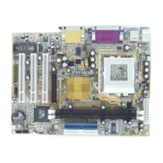
Introduction Chapter 1 Chapter 1 Introduction Introduction Chapter 1 Introduction 1.1. Mainboard And PC99 ATX External Connector Layout The U601BS Mainboard User Manual Page 5... -
Page 6: Overview
1.2. Overview 1.2.1. The U601BS Mainboard The U601BS is a Micro-ATX Socket 370 CPU platform. It based on the VIA Apollo PLE133T. It is able to support three different FSB Clock speeds: 66 MHz, 100 MHz or 133 MHz. It also supports up to 1GB of SDR SDRAM. It has four USB ports, three PCI slots. - Page 7 DC power supply from +1.050V to +1.825V. System Memory The U601BS mainboard has two 168-pin SDR SDRAM DIMM modules on- board. These modules are able to support PC-133 and PC-100 SDRAM mod- ules. A maximum memory of 1GB is supported.
- Page 8 One WOL connector supports Wake-On-LAN functionality. USB Ports The U601BS mainboard is equipped with 4 USB ports. USB allows data exchange between your computer and a wide range of simultaneously accessible external Plug and Play peripherals. USB 1 and USB 2 are external ports.
-
Page 9: System Health Monitor Functions
(Driver Utility) will automatically appear. Click the Hardware Monitoring button, choose the chipset, model number and the OS that is installed. Please refer to the CD “Readme” file for further installation instructions. The U601BS Mainboard User Manual Page 9... -
Page 10: System Intelligence
ACPI Ready The mainboard is designed to meet the ACPI (Advanced Configuration and Power Interface) specification. ACPI has energy saving features that support OS Direct Power Management (OSPM) for round the clock PC operation. Page 10 The U601BS Mainboard User Manual... -
Page 11: Chapter 2:- Hardware Installation
Universal Serial Port 2 USB2 CN18 Game/Audio Port Audio/Game CN19 VGA Port These items are manufacture options. Please see Appendix A for fur- ther details about these options and how they can be obtained. The U601BS Mainboard User Manual Page 11... -
Page 12: Installation Steps
Before you start installing your mainboard we strongly recommend that you use a grounded anti-static mat. We further recommend that you attach an anti-static wristband, which is grounded at the same location as the mat, to your wrist. Page 12 The U601BS Mainboard User Manual... -
Page 13: Expansion Slots, Jumpers And Internal Connectors
Hardware Installation 2.3. Expansion Slots, Jumpers and Internal Connectors The U601BS Mainboard User Manual Page 13... -
Page 14: Cpu, Memory And Expansion Slots
CPU. 2.4.2. Memory Modules The U601BS mainboard has two 168-pin DIMM slots and are able to support a maximum of 1GB PC-100/PC-133 SDR SDRAM. The DIMM slots are located on the right hand side of the board. To install the DIMM’s into these slots, make sure the white lever at each side of the slot has been pulled down to an angle of approximately 45°. -
Page 15: Pci Slots
When you are inserting your PCI card make sure that the pins are correctly aligned. When the pins 11 Pins are properly aligned with hole’s in the slot, push down gen- tly. PCI3 PCI2 PCI1 The U601BS Mainboard User Manual Page 15... -
Page 16: Internal Connectors
Type: 40 pin blocks The U601BS mainboard has two IDE connectors: a primary and secondary. Each IDE connector can support two IDE drives. These mainboards can there- fore support up to four IDE devices each. If you install two hard drives, you need to configure the second drive to slave mode in the BIOS setup. -
Page 17: Atx Power Supply Connector
Make sure the pins are correctly aligned. Find the correct orientation and push the plug down firmly. ATX Power Supply Connector +5VDC +12V +5VDC 5VSB -5VDC PWR_OK +5VDC +5VDC PS_ON# +3.3VDC -12VDC +3.3VDC +3.3VDC Pin 1 Pin 11 The U601BS Mainboard User Manual Page 17... -
Page 18: Wol (Wake-On-Lan) Connector
The internal USB connectors allow you to add on an optional kit to ex- pand the total number of USB ports available. The U601BS has two internal USB connectors (CN30 and CN31). This enables you to use an extra two USB devices. -
Page 19: Aux-In Connector
2.5.8. AUX-IN Connector Connector: CN 45 (AUX-IN) Type: 4 pin un-housed The U601BS mainboard comes with an AUX-IN connector The AUX-IN connector allows you to receive signals from other audio devices like a radio or tape. Auxiliary-IN Connector Left Channel AUX-IN... -
Page 20: Pw: Power On/Off And External Suspend Switch Connector
Any read and write activity by the HDD will turn this LED on. 2.6.4. Reset Button Connector If you connect this connector, you will be able to reset you computer by press- ing the reset button at the front of the chassis. Page 20 The U601BS Mainboard User Manual... -
Page 21: Speaker And Power Led Connectors
2.8.2. PS/2 Mouse Connector. Connector: CN 2 Type: 6 pin female This connector only supports a PS/2 mouse plug. If a PS/2 mouse is de- tected then IRQ 12 will be directed to CN 2. The U601BS Mainboard User Manual Page 21... -
Page 22: Serial Port (Com)
MIDI device. All these motherboards have 3D audio interfaces onboard. SPK-OUT LINE-IN MIC-IN Page 22 The U601BS Mainboard User Manual... -
Page 23: Vga Port Connecto
Insert the jumper cap on Pin 2 and Pin 3 for 3 ~ 5 seconds. Pull out the jumper cap and replace it on Pin 1 and Pin 2. Turn your PC on and run the BIOS setup program. JP: Clear CMOS PIN: 1 2 3 The U601BS Mainboard User Manual Page 23... -
Page 24: Chapter 3:- Managing The Pc Bios
Esc : Quit Time, Date, Hard Disk Type ... Note! BIOS software is continuously updated therefore the BIOS menus and the descriptions that are given in this manual are for reference purposes only. Page 24 The U601BS Mainboard User Manual... -
Page 25: Standard Cmos Setup
Hard Drive parameters. Move the selection bar to the IDE Hard Drive you want to configure. Press the "ENTER" key. If you select “AUTO” the system BIOS will detect the HDD type automatically. The U601BS Mainboard User Manual Page 25... - Page 26 16384K Drive A /B The U601BS mainboard series can support up to two floppy disk drives. These two selection fields allow you to select the floppy drives that are installed on your computer. Select the correct specifications for the diskette drive(s) in- stalled on your computer.
-
Page 27: Advanced Bios Features
PCs have an additional (external) cache memory. When the CPU requests data, the system transfers the requested data from the main DRAM into cache memory, for faster access by the CPU. The U601BS Mainboard User Manual Page 27... - Page 28 L2 cache is accurate. Processor Number Feature If you have a Pentium processor onboard you should enable this option. This will alow the serial code of the Pentium processor to be published on certain applications. Page 28 The U601BS Mainboard User Manual...
- Page 29 Typematic Rate Setting The keyboard controller determines the rate at which the keystrokes from the keyboard are repeated. If you enable this option then the typematic rate and the typematic delay can be selected. The U601BS Mainboard User Manual Page 29...
- Page 30 These fields allow you to change the Video BIOS location from ROM to RAM. Information access is faster through RAM than ROM. Therefore when you en- able this option you will enhance your system performance. Page 30 The U601BS Mainboard User Manual...
-
Page 31: Advanced Chipset Features
Some memory modules are unable to deal with short delay times. We recommend that you set this delay time between 2 and 3 CLK’s (the default is 3). If your system becomes unstable we recommend that you in- crease the delay time. The U601BS Mainboard User Manual Page 31... - Page 32 This should be enabled if your system has a USB installed on the system board and you want to use it. Even when so equipped, if you add a higher perform- ance controller, you will need to disable this feature. Page 32 The U601BS Mainboard User Manual...
- Page 33 When enabled, PCI#2 will be disconnected if max retries are attempted with- out success. AGP Master 1 WS Write When Enabled, writes to the AGP(Accelerated Graphics Port) are executed with one wait states. The U601BS Mainboard User Manual Page 33...
-
Page 34: Integrated Peripherals
: EPP 1.9 Onboard Legacy Audio :Enabled Sound Blaster :Disabled SB I/O Base Address :220H SB IRQ Select :IRQ 5 SB DMA Select :DMA 1 MPU-401 :Disabled MP-401 I/O Address :330-333H Game Port (200—207H) :Enabled Page 34 The U601BS Mainboard User Manual... - Page 35 Disabled in this field. Onboard Serial Port 1/Port 2 These two selection fileds allow you to select the I/O address and correspond- ing interrupt for the first and second serial ports. The U601BS Mainboard User Manual Page 35...
- Page 36 “enabled” setting should be retained. Sound Blaster If a Sound Blaster is going to be used then this field needs to be enabled. If you are not using a Sound Blaster then retain the default “disabled” setting. Page 36 The U601BS Mainboard User Manual...
-
Page 37: Power Management Setup
Windows 98, that supports the ACPI function. During the installation of the OS, like Windows 98, you need to enter a certain set of parameters. For fur- ther details please refer to the OS user manual. (continued on the next page.) The U601BS Mainboard User Manual Page 37... - Page 38 Power Down which ranges from 1 min. to 15 min. and disable. !HDD Power Down When enabled and after the set time of system inactivity, the hard disk drive will be powered down while all other devices remain active. Page 38 The U601BS Mainboard User Manual...
- Page 39 Video Electronics Standards to select video power man- agement values. Soft-Off by PWRBTN Pressing the power button for more than 4 seconds forces the system to enter the Soft-Off state when the system has “hung”. The U601BS Mainboard User Manual Page 39...
- Page 40 When an I/O device wants to gain the attention of the operating system, it signals this by causing an IRQ to occur. When the operating system is ready to respond to the request, it interrupts itself and performs the service. Page 40 The U601BS Mainboard User Manual...
-
Page 41: Pnp/Pci Configuration
Award Plug and Play BIOS has the capacity to automatically configure all of the boot and Plug and Play compatible devices. However, this capability means absolutely nothing unless you are using a Plug and Play operating system such as Windows 98. The U601BS Mainboard User Manual Page 41... -
Page 42: Pc Health Status
This field will show you the current CPU Cooling FAN1 speed. Current Chassis FAN Speed This field will show you the current Chassis Fan speed. Vcore This field and the files show you the current system voltage. Page 42 The U601BS Mainboard User Manual... -
Page 43: Frequency/Voltage Control
Set User Password ! Power Management Setup Save & Exit Setup ! PNP/PCI Configuration Exit Without Saving ! Health Status ← ↑ ↓ → : Select Item ESC : Quit Load Optimized Defaults The U601BS Mainboard User Manual Page 43... -
Page 44: Set Supervisor Password
Whenever you turn on the PC, it will request the user to enter the Password in order to boot up your system. Without the correct password, the PC system will stop and the operating system will not be loaded. Page 44 The U601BS Mainboard User Manual... -
Page 45: Set User Password
B. When there is no password stored in the "SUPERVISOR PASS WORD" 1. When "Setup" is selected in Security Option: Users can use the "User Password" to log into the BIOS setup program, and they can change any of the BIOS settings. The U601BS Mainboard User Manual Page 45... -
Page 46: Save & Exit Setup/Exit Without Saving
CMOS RAM. If you do not want to save any of the changes, or settings you selected in the BIOS SETUP utility, move the selection bar to the “EXIT WITHOUT SAVING” option. Press the “Enter” key. Then press “Y” Page 46 The U601BS Mainboard User Manual... -
Page 47: Appendix A: Optional Items
The Sony Phillips Digital Interface, S/PDIF, connector is a digital interface that can be used to improve the quality of the sound output from your system. Top View of the S/PDIF S/PDIF data input signal Ground The U601BS Mainboard User Manual Page 47... - Page 48 Managing The PC BIOS This page has intentionally been left blank Page 48 The U601BS Mainboard User Manual...
Need help?
Do you have a question about the U601BS and is the answer not in the manual?
Questions and answers