Pilz PNOZ X9 Operating Manual
Safety relays
Hide thumbs
Also See for PNOZ X9:
- Operating instructions manual (16 pages) ,
- Operating manual (31 pages)
Table of Contents
Advertisement
Quick Links
Advertisement
Table of Contents

Related Manuals for Pilz PNOZ X9


Summary of Contents for Pilz PNOZ X9
- Page 1 PNOZ X9 Safety relays Operating Manual-19526-EN-10...
- Page 2 Preface This document is the original document. All rights to this documentation are reserved by Pilz GmbH & Co. KG. Copies may be made for the user's internal purposes. Suggestions and comments for improving this documenta- tion will be gratefully received.
-
Page 3: Table Of Contents
Operation ..........................Status indicators ........................Faults – Interference ......................Dimensions in mm ......................... Technical details ........................Safety characteristic data ......................Supplementary data ......................Service life graph ........................Order reference ........................EC declaration of conformity ....................Operating Manual PNOZ X9 19526-EN-10... -
Page 4: Introduction
PNOZ X9 Introduction Validity of documentation This documentation is valid for the product PNOZ X9. It is valid until new documentation is published. This operating manual explains the function and operation, describes the installation and provides guidelines on how to connect the product. -
Page 5: Safety
This gives advice on applications and provides information on special fea- tures. Safety Intended use The safety relay PNOZ X9 provides a safety-related interruption of a safety circuit. The safety relay meets the requirements of EN 60947-5-1 and EN 60204-1 and may be used in applications with: E-STOP pushbuttons... -
Page 6: Use Of Qualified Personnel
Note for overvoltage category III: If voltages higher than low voltage (>50 VAC or >120 VDC) are present on the unit, connected control elements and sensors must have a rated insulation voltage of at least 250 V. Operating Manual PNOZ X9 19526-EN-10... -
Page 7: Unit Features
The circuit is redundant with built-in self-monitoring. The safety function remains effective in the case of a component failure. The correct opening and closing of the safety function relays is tested automatically in each on-off cycle. Operating Manual PNOZ X9 19526-EN-10... -
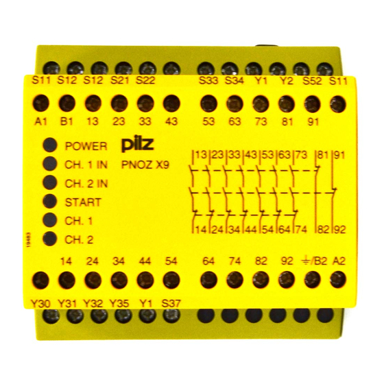
Page 8: Block Diagram/Terminal Configuration
III), Protective separation (overvoltage category II) Function Description The safety relay PNOZ X9 provides a safety-oriented interruption of a safety circuit. When supply voltage is supplied the "POWER" LED is lit. The unit is ready for operation when the feedback loop Y1-Y2 and the start circuit S33-S34 are closed. -
Page 9: Timing Diagram
Out semi OUT: Semiconductor output switch state [1]: Automatic start [2]: Manual start [3]: Monitored start a: Input circuit closes before start circuit b: Start circuit closes before input circuit : Switch-on delay : Delay-on de-energisation Operating Manual PNOZ X9 19526-EN-10... -
Page 10: Installation
(on the input circuit) does not overload the proximity switch. With a 24 VDC supply voltage via terminals B1, B2, the power supply must comply with the regulations for extra low voltages with safe electrical separation (SELV, PELV). Operating Manual PNOZ X9 | 10 19526-EN-10... -
Page 11: Preparing For Operation
Important for detection of shorts across contacts: As this function for detecting shorts across contacts is not failsafe, it is tested by Pilz during the final control check. If there is a danger of exceeding the cable runs, we recommend the following test after the installation of the device: 1. - Page 12 22]). NOTICE Operation with a light guard or safety switch It must not be possible to switch off the supply voltage for the PNOZ X9 separately from the supply voltage for the light guard or safety switch. Start circuit Single-channel, dual-channel...
- Page 13 Y31, Y30: External supply voltage Legend S1/S2: E-STOP/safety gate switch S3: Reset button : Switch operated : Gate open : Gate closed INFORMATION With automatic and manual start, Y1 and S37 must not be linked. Operating Manual PNOZ X9 | 13 19526-EN-10...
-
Page 14: Operation
Start circuit is closed. CH.1 IN Channel 1 input circuit is closed. CH.2 IN Channel 2 input circuit is closed. CH.1 OUT Channel 1 safety contacts are closed. CH.2 OUT Channel 2 safety contacts are closed. Operating Manual PNOZ X9 | 14 19526-EN-10... -
Page 15: Faults - Interference
Contact malfunctions: If the contacts have welded, reactivation will not be possible after the input circuit has opened. LED "POWER" does not light: Short circuit or no supply voltage. Dimensions in mm 75 (2.95") 90 (3.54") 87 (3.42") Operating Manual PNOZ X9 | 15 19526-EN-10... -
Page 16: Technical Details
50 mA 50 mA Start circuit DC 100 mA 100 mA 100 mA Feedback loop DC 100 mA 100 mA 100 mA Min. input resistance at power-on 89 Ohm 89 Ohm 89 Ohm Operating Manual PNOZ X9 | 16 19526-EN-10... - Page 17 Number of output con- tacts Safety contacts (N/O), instantaneous Auxiliary contacts (N/C) 2 Max. short circuit current 1 kA 1 kA 1 kA Utilisation category In accordance with the standard EN 60947-4-1 EN 60947-4-1 EN 60947-4-1 Operating Manual PNOZ X9 | 17 19526-EN-10...
- Page 18 240 V AC G. P. 240 V AC G. P. With current Voltage 24 V DC Resistive 24 V DC Resistive 24 V DC Resistive With current Pilot Duty B300, R300 B300, R300 B300, R300 Operating Manual PNOZ X9 | 18 19526-EN-10...
- Page 19 4 contacts Conv. therm. current with 5 contacts 3,5 A 3,5 A 3,5 A Conv. therm. current with 6 contacts 3,2 A 3,2 A 3,2 A Conv. therm. current with 7 contacts Operating Manual PNOZ X9 | 19 19526-EN-10...
- Page 20 Min. start pulse duration with a monitored start 50 ms 50 ms 50 ms Supply interruption before de-energisation 35 ms 35 ms 35 ms Simultaneity, channel 1 and 2 max. 150 ms 150 ms 150 ms Operating Manual PNOZ X9 | 20 19526-EN-10...
- Page 21 ABS UL 94 V0 ABS UL 94 V0 PPO UL 94 V0 PPO UL 94 V0 PPO UL 94 V0 Connection type Screw terminal Screw terminal Screw terminal Mounting type Fixed Fixed Fixed Operating Manual PNOZ X9 | 21 19526-EN-10...
-
Page 22: Safety Characteristic Data
EN 61508-6 and IEC 61511 and as the proof test interval and mission time in accordance with EN 62061. All the units used within a safety function must be considered when calculating the safety characteristic data. Operating Manual PNOZ X9 | 22 19526-EN-10... -
Page 23: Supplementary Data
If the service life graphs are not accessible, the stated PFH value can be used irrespective of the switch frequency and the load, as the PFH value already considers the relay's B10d value as well as the failure rates of the other components. Operating Manual PNOZ X9 | 23 19526-EN-10... -
Page 24: Service Life Graph
24 VAC; 24 VDC Screw terminals 774609 PNOZ X9 100 - 120 V AC; 24 V DC Screw terminals 774605 PNOZ X9 200 - 230 V AC; 24 V DC Screw terminals 774606 Operating Manual PNOZ X9 | 24 19526-EN-10... -
Page 25: Ec Declaration Of Conformity
European Parliament and of the Council. The complete EC Declaration of Conformity is available on the Internet at www.pilz.com/support/downloads. Representative: Norbert Fröhlich, Pilz GmbH & Co. KG, Felix-Wankel-Str. 2, 73760 Ost- fildern, Germany Operating Manual PNOZ X9... - Page 26 We are represented internationally. Please refer to our homepage www.pilz.com for further details or contact our headquarters. Headquarters: Pilz GmbH & Co. KG, Felix-Wankel-Straße 2, 73760 Ostfildern, Germany Telephone: +49 711 3409-0, Telefax: +49 711 3409-133, E-Mail: info@pilz.com, Internet: www.pilz.com...
Need help?
Do you have a question about the PNOZ X9 and is the answer not in the manual?
Questions and answers