Pilz PNOZ X2.1C Operating Manual
Safety relays
Hide thumbs
Also See for PNOZ X2.1C:
- Operating instructions manual (16 pages) ,
- Operating instructions manual (12 pages)
Table of Contents
Advertisement
Quick Links
Advertisement
Table of Contents

Related Manuals for Pilz PNOZ X2.1C


Summary of Contents for Pilz PNOZ X2.1C
- Page 1 PNOZ X2.1C Safety relays Operating Manual-1003973-EN-07...
- Page 2 Preface This document is a translation of the original document. All rights to this documentation are reserved by Pilz GmbH & Co. KG. Copies may be made for internal purposes. Suggestions and comments for improving this documentation will be gratefully received.
-
Page 3: Table Of Contents
Function Description Operating modes Timing diagram Installation Wiring Preparing for operation Operation Status indicators Faults – Interference Dimensions in mm Technical details Safety characteristic data Supplementary data Service life graph Order reference EC declaration of conformity Operating Manual PNOZ X2.1C 1003973-EN-07... -
Page 4: Introduction
PNOZ X2.1C Introduction Validity of documentation This documentation is valid for the product PNOZ X2.1C. It is valid until new documentation is published. This operating manual explains the function and operation, describes the installation and provides guidelines on how to connect the product. -
Page 5: Safety
Safety Intended use The safety relay PNOZ X2.1C provides a safety-related interruption of a safety circuit. The safety relay meets the requirements of EN 60947-5-1, EN 60204-1 and VDE 0113-1 and may be used in applications with E-STOP pushbuttons... -
Page 6: Use Of Qualified Personnel
Note for overvoltage category III: If voltages higher than low voltage (>50 VAC or >120 VDC) are present on the unit, connected control elements and sensors must have a rated insulation voltage of at least 250 V. Operating Manual PNOZ X2.1C 1003973-EN-07... -
Page 7: Unit Features
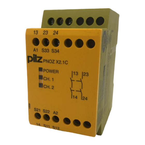
Block diagram/terminal configuration S33 S34 PNOZ X2.1C POWER CH. 1 CH. 2 *Insulation between the non-marked area and the relay contacts: Basic insulation (over- voltage category III), Protective separation (overvoltage category II) Operating Manual PNOZ X2.1C 1003973-EN-07... -
Page 8: Function Description
PNOZ X2.1C Function Description The safety relay PNOZ X2.1C provides a safety-oriented interruption of a safety circuit. When supply voltage is supplied the "POWER" LED is lit. The unit is ready for operation when the start circuit S33-S34 is closed. -
Page 9: Timing Diagram
Calculation of the max. cable length l in the input circuit: lmax / km = max. overall cable resistance (see Technical details [ 13]) lmax / km = cable resistance/km Use copper wire that can withstand 60/75 °C. Operating Manual PNOZ X2.1C 1003973-EN-07... -
Page 10: Preparing For Operation
Important for detection of shorts across contacts: As this function for detecting shorts across contacts is not failsafe, it is tested by Pilz during the final control check. If there is a danger of exceeding the cable runs, we recommend the following test after the installation of the device: 1. -
Page 11: Operation
When the relay outputs are switched on, the mechanical contact on the relay cannot be tested automatically. Depending on the operational environment, measures to detect the non-opening of switching elements may be required under some circumstances. Operating Manual PNOZ X2.1C 1003973-EN-07... -
Page 12: Status Indicators
1 minute, the unit is ready for operation again. Contact malfunctions: If the contacts have welded, reactivation will not be possible after the input circuit has opened. LED "POWER" does not light: Short circuit or no supply voltage. Operating Manual PNOZ X2.1C 1003973-EN-07... -
Page 13: Dimensions In Mm
24 V Start circuit DC 24 V Feedback loop DC 24 V Current at Input circuit DC 25 mA Start circuit DC 30 mA 30 mA Feedback loop DC Min. input resistance at power-on 21 Ohm Operating Manual PNOZ X2.1C 1003973-EN-07... - Page 14 EN 60947-5-1 240 A²s Max. melting integral Blow-out fuse, quick 10 A Blow-out fuse, slow Blow-out fuse, gG 10 A Circuit breaker 24V AC/DC, characteristic B/C Conventional thermal current Contact material AgSnO2 + 0,2 µm Au Operating Manual PNOZ X2.1C 1003973-EN-07...
- Page 15 III / II Pollution degree Rated insulation voltage 250 V Rated impulse withstand voltage 4 kV Protection type Housing IP40 IP20 Terminals Mounting area (e.g. control cabinet) IP54 Mechanical data Mounting position 10,000,000 cycles Mechanical life Operating Manual PNOZ X2.1C 1003973-EN-07...
-
Page 16: Safety Characteristic Data
A safety function's SIL/PL values are not identical to the SIL/PL values of the units that are used and may be different. We recommend that you use the PAScal software tool to calculate the safety function's SIL/PL values. Operating Manual PNOZ X2.1C 1003973-EN-07... -
Page 17: Supplementary Data
To increase the service life, sufficient spark suppression must be provided on all output contacts. With capacitive loads, any power surges that occur must be noted. With DC con- tactors, use flywheel diodes for spark suppression. Operating Manual PNOZ X2.1C 1003973-EN-07... -
Page 18: Order Reference
European Parliament and of the Council. The complete EC Declaration of Conformity is available on the Internet at www.pilz.com/support/downloads. Representative: Norbert Fröhlich, Pilz GmbH & Co. KG, Felix-Wankel-Str. 2, 73760 Ost- fildern, Germany Operating Manual PNOZ X2.1C... - Page 19 Back cover Support Technical support is available from Pilz round the clock. Americas Australia Scandinavia +45 74436332 Brazil +61 3 95600621 +55 11 97569-2804 Spain Canada Europe +34 938497433 +1 888-315-PILZ (315-7459) Austria Switzerland Mexico +43 1 7986263-0 +41 62 88979-30...
Need help?
Do you have a question about the PNOZ X2.1C and is the answer not in the manual?
Questions and answers