
Related Manuals for Taurus Multi-gym UltraForce


Summary of Contents for Taurus Multi-gym UltraForce
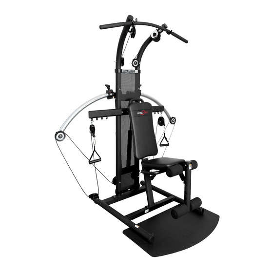
- Page 1 Assembly and Operating Instructions max. 120 kg ~ 60 Min. 33 kg L 108 | W 56 | H 139 TFUF.01.02 Art. No. TF-UF-PRO Multi-gym UltraForce...
- Page 2 Ultra Force...
-
Page 3: Table Of Contents
Content GENERAL INFORMATION Technical Data Personal Safety Set-Up Place ASSEMBLY General Instructions Scope of Delivery Parts Overview Warning notes/warning sticker Assembly STORAGE AND TRANSPORT General Instructions Transportation Wheels WORKOUT INSTRUCTIONS General training instructions Exercise and safety notes Exercise manual Equipment settings Stretching exercises for leg &... - Page 4 ORDERING SPARE PARTS Serial Number and Model Name Parts List Exploded Drawing WARRANTY CONTACT Ultra Force...
- Page 5 With Taurus® fitness equipment, the focus is on what sport is all about: maximum performance! Therefore, the equipment is developed in close consultation with athletes and sports scientists.
- Page 6 ABOUT THIS MANUAL Please carefully read the entire manual before installation and first use. The manual will help you to quickly set up the system and explains how to safely use it. Make sure that all persons exercising with the equipment (especially children and persons with physical, sensory, mental or motor disabilities) are informed about this manual and its contents in advance.
-
Page 7: General Information
GENERAL INFORMATION Technical Data Weight and dimensions: Article weight (gross, including packaging): 88.6 kg Article weight (net, without packaging): 87 kg Packaging dimensions of the box (L x W x H): No. 1 approx. 151 cm x 49 cm x 22 cm, weight: 42 kg (gross, including packaging) No. -
Page 8: Personal Safety
Personal Safety DANGER ⚠ Before you start using the equipment, you should consult your physician that this type of exercise is suitable for you from a health perspective. Particularly affected are persons who: have a hereditary disposition to high blood pressure or heart disease, are over the age of 45, smoke, have high cholesterol values, are overweight and/or have not exercised regularly in the past year. -
Page 9: Set-Up Place
Set-Up Place WARNING ⚠ Do not place the equipment in main corridors or escape routes. ⚠ CAUTION Choose a location in which to place the equipment such that there is enough free space/ clearance to the front, the rear and to the sides of the equipment. The training room should be well ventilated during training and not be exposed to any draughts. -
Page 10: Assembly
ASSEMBLY General Instructions ⚠ DANGER Do not leave any tools, packaging materials such as foils or small parts lying around, as otherwise there is a danger of suffocation for children. Keep children away from the equipment during assembly. ⚠ WARNING Pay attention to the instructions attached to the equipment in order to reduce the risk of injuries. -
Page 11: Scope Of Delivery
Scope of Delivery The scope of delivery consist of the following parts. At the beginning, check whether all parts and tools belonging to the device are included in the scope of delivery and whether damage has occurred. In the event of complaints, the contractual partner must be contacted directly. -
Page 12: Parts Overview
Parts Overview Ultra Force... -
Page 13: Warning Notes/Warning Sticker
Warning notes/warning sticker IMPORTANT: Please observe the attachment of the following warning and attention stickers on your equipment: CAUTION LABEL 1 If you are not using the lat bar, always hang it in the holder. WARNING LABEL 1 If you do not read and follow the safety instructions provided in the user instructions and video, this MAY RESULT IN SERIOUS INJURIES OR DEATH. - Page 14 WARNING LABEL 3 Crushing hazard! Keep hands away while using! WARNING LABEL 5 (6 positions) Do not touch the pulleys and mobile parts. Ultra Force...
- Page 15 WARNING LABEL 4 (2 positions) WARNING! Make sure that the pin is locked in the position before you begin the exercise. WARNING LABEL 7 (2 positions) WARNING! When you do exercises while standing, keep your feet on the ground plate.
- Page 16 CAUTION LABEL 2 NOTE! In order to transport the equipment, we recommend doing this with two persons. WARNING LABEL 5 (6 positions) WARNING! Do not touch the pulleys and mobile parts. WARNING LABEL 6 (2 positions) WARNING! Crushing hazard - only use adjusting arm with free hands. WARNING LABEL 8 (2 positions) WARNING! Content under pressure;...
-
Page 17: Assembly
Assembly Before assembly, take a close look at the individual assembly steps shown and carry out the assembly in the order given. NOTICE First loosely screw all parts together and check that they fit properly. Tighten the screws using the tool only when you are instructed to do so. - Page 18 Required parts for step 1: Step 1: Assembly base frame Turn the main frame with the warning notes downward. Position the ground plate on the main frame on the opposite side of the transport wheels and make sure that the bent side of the ground plate shows outward. Align the holes in the ground plate with the main frame and attach the parts with the four screws.
- Page 19 Required parts for step 2: Step 2: Assembly of rear frame Turn around the rear frame so that it is on the auxiliary strut and the warning notes point downwards. Place perforated cover and the crossbar on the frame and align the holes.
- Page 20 All nuts and screws are brought in from the front to back - with the nut on the backside. Required parts for step 3: Step 3: Assembly backrest supporting frame Loosen the screws from the handle of the backrest. Mount the handle with the previously loosened screws on the small crossbar on the upper end of the backrest frame.
- Page 21 Required parts for step 4: Step 4: Assembly frame components Carefully straighten up the rear frame and place it on the rear traverse of the main frame. The crossbar and the perforated cover point forward. Mount the parts with four screws and spring washers and tighten these by hand.
- Page 22 Position the frame with the backrest by aligning the holes of the main frame with the holes of the frame with the backrest. Tighten the parts with two screws and spring washers. Align the holes on the upper end of the backrest with the central holes in the crossbar. Mount the two Allen screws and two cap nuts and tighten these by hand.
- Page 23 Required parts for step 5: Step 5: Assembly covers Remove the two (M6 x 29mm) hex head screws from the upper cover plates of the perforated metal plate with the Phillips wrench (included in delivery) and separate the front and back sides. NOTICE The cover plate with the UltraForce logo belongs on the top on the front side.
- Page 24 Required parts for steps 6 and 7: Step 6: Assembly of seat Loosen the screws from the underside of the seat. Place the seat frame on the backside of the seat and make sure that the long socket pin and the bracket are in the same direction as the small end of the seat.
- Page 25 Step 7: Assembly of leg extension Place the upper end of the leg extension tube on the bracket from the removable leg extension unit. NOTICE The warning note points towards the seat. Slide the barrel nut through the removable leg extension unit and the leg extension tube.
- Page 26 Required parts for step 8: Step 8: Assembly swivel arms and cylinder Place yourself behind the station. Slide the right swivel arm on the supportive bar on the upper crossbar of the main frame. The label from the swivel arm points forward. Mount the right swivel arm with a large washer and a hex head screw.
- Page 27 NOTICE All nuts and screws are brought in from the front to back - with the nut on the backside. Lift the right swivel arm and the resistance cylinder. Mount the upper end of the cylinder with the lower part of the right adjusting unit with a cap nut and a hex head screw.
- Page 28 Required parts for step 9: Step 9: Assembly pulleys Determine the positions of the individual pulley holders, see markings. Take the two pulleys without the UltraForce logo and the two pulley brackets, which are designated for the lower end of the main frame. Mount the pulleys on the lower backside of the main frame with two Allen screws and two cap nuts.
- Page 29 Required parts for step 10: Step 10: Assembly of the cable Lay out and unwind cable. Slide the chrome pulley to one end of the cable. Slide the other two pulleys to the other end of the cable. This keeps the cable unwind during installation. Mount the chrome pulley with bracket on the upper right frame with a thread screw and a cap nut, see image.
- Page 30 Ultra Force...
- Page 31 Step 11: Mount the lat bar on the large snap hook on the upper frame. Then place the lat bar in the designated hook on the upper frame. Mount the handles with the large snap hook on the end of the cable on the crossbar. NOTICE The foot loops can now be suspended on the hook from the leg extension unit.
-
Page 32: Storage And Transport
STORAGE AND TRANSPORT General Instructions ⚠ WARNING The storage location should be chosen so that improper use by third parties or children can be prevented. If your equipment does not have transportation wheels, the equipment must be disassembled before transportation. ࣑... -
Page 33: Workout Instructions
WORKOUT INSTRUCTIONS The Taurus UltraForce is a multi-functional multi-gym for achieving many training targets. Muscle toning and tightening are possible as well as an improvement of strength-endurance and an effective support in losing weight. We have compiled some important training tips for you so you can achieve your training targets as effectively, safely and lastingly as possible. -
Page 34: Exercise And Safety Notes
Clothing All training clothing should sit loosely and comfortably (for enough freedom of movement) and give self-confidence. Never wear rubber and synthetic clothing; such materials impair the evaporation of sweat and may cause a dangerous increase in body temperature. Wear comfortable, supportive sport shoes with anti-slip soles like running or aerobic shoes. -
Page 35: Exercise Manual
Exercise manual A detailed description of all exercises can be found in the included training instructions. Equipment settings Set resistance with glide-n-lock technology The resistance setting is done quickly. Simply pull up the glide-n-lock slider to unlock it from its current position. - Page 36 Ultra Force...
-
Page 37: Stretching Exercises For Leg & Chest Muscles
Stretching exercises for leg & chest muscles 1. Exercise: Stretching of front thigh / leg extension (quadriceps) • Stable position, grab arches of feet • Pull heel towards buttocks, knee points downwards (no abduction) • Straight upper body, avoid tilting the pelvic forward (hollow back) by tensing the abdominal muscles •... - Page 38 3. Exercise: Stretching the calf muscles (gastrocnemius) • Place feet parallel to each other pointing forward, the heels touch the floor • Support yourself on a chair coming from a lunge • Move your body weight to the front leg, press your heel from the rear leg towards the floor and hold the contact •...
-
Page 39: Workout Journal
Workout journal Date Time (min.) Training weight Calories burnt Body weight Ø Pulse Distance Resistance level I feel ... -
Page 40: Troubleshooting, Care And Maintenance
TROUBLESHOOTING, CARE AND MAINTENANCE General Instructions ⚠ WARNING Do not make any improper changes to the equipment. CAUTION ⚠ Damaged or worn components may affect your safety and the life of the equipment. Therefore, immediately replace damaged or worn components. In such a case, contact the contract partner. -
Page 41: Maintenance And Inspection Calendar
Maintenance and Inspection Calendar To avoid damage from body sweat, the equipment must be cleaned with a damp towel (no solvents!) after each training session. The following routine tasks must be performed at the specified intervals: Part Weekly Monthly Quarterly Screw connections Pulleys and cable routing Wheels and rope guide... -
Page 42: Recommended Accessories
RECOMMENDED ACCESSORIES To make your training experience even more efficient and pleasant, we recommend that you add suiting accessories to your fitness equipment. This could be a floor mat, for example, which makes your fitness equipment stand more securely and also protects the floor from falling sweat, but it could also be additional handrails on some treadmills or silicone spray to keep moving parts in good shape. -
Page 43: Ordering Spare Parts
10 of this operating manual. NOTICE The serial number of your equipment is unique. It's located on a white sticker. Enter the serial number in the appropriate field. Serial number: Brand / Category: Taurus / multi gym Model Name: Ultra Force Article Number: TF-UF-PRO... -
Page 44: Parts List
Parts List Name (ENG) Specification Qty. UPRRIGHT FRAME PULLEY WHEEL LOGO PLATE BDE7144 ROUND HEAD CROSS TAPPING SCREW M2x6 PULLEY WHEEL PBG107 BEARING 6202Z PLASTIC PULLEY COVER PCZ3535 OIL BEARING NBZ201588 PULLEY BRACKET GUARDS FRAME IRON PLATE NAB081419328 FRONT TOP COVER CAP PCZ36040A FRONT BOTTOM COVER CAP PCZ36041C... - Page 45 PLASTIC ROLLER CAP(L) PBK6457A PLASTIC ROLLER CAP(R) PBK6457B ALLEN BOLT M8x46(10mm) CROSS BOLT M6x20 FOOT PAD PCF1226 WASHER DRILL CROSS TAPPING SCREW Ø4x20 TOP FRAME TUBE (L) PULLEY WHEEL PBG107A CHRAME PULLEY ASSEMBLY ALLEN BOLT M10x38(10mm) TOP FRAME TUBE (R) TOP PULLEY WHEEL BRACKET UPPER FRAME(R) FOAM GRIP HOOK Ø12xØ15x125...
- Page 46 SWING ARM PULLEY WHEEL BRACKET WITH BUSHING(R) SWING ARM PULLEY WHEEL BRACKET WITH BUSHING(L) TOP PULLEY WHEEL BRACKET(L) RESISTANCE CYLINDER FBN88022 RESISTANCE IRON CORE NBB8128 CYLINDER HOUSING TUBE 50.8x1.5tx462 RESISTANCE PLASTIC CAP PEC508378 RESISTANCE PLASTIC CAP W/PIVOT PCD508452 CABLE NCJ55200 CLIMBERS CLIP NBZ880 HANDLES...
- Page 47 FLAT END ALLEN BOLT M8x15 FOOT HARNESS CLIRNBERS CLIP (SMALL) NBD6608 ALLEN BOLT M10x72(15mm) ALLEN BOLT M10x112(20mm) ALLEN BOLT M10x57(15mm) ALLEN BOLT M10x30 SPRING WASHER M10x2.5t HEX BOLT M8x20 WASHER Ø30xØ10x2.0t WASHER Ø20xØ9x2.0t HEX BOLT M8x49(10mm) ACORN NUT ALLEN SPACER BOLT SAE61673 ALLEN BOLT SAE61620...
-
Page 48: Exploded Drawing
Exploded Drawing Ultra Force... -
Page 49: Warranty
WARRANTY Training equipment from Taurus® is subject to strict quality control. However, if a fitness equipment purchased from us does not work perfectly, we take it very seriously and ask you to contact our customer service as indicated. We are happy to help you by phone via our service hotline. - Page 50 Warranty Conditions For the warranty to be valid, the following steps must be taken: Please contact our customer service by email or phone. If the product under warranty has to be sent in for repair, the seller bears costs. After expiry of the warranty, the buyer bears the costs of transport and insurance.
-
Page 51: Contact
CONTACT TECHNICAL SUPPORT TECHNICAL SUPPORT & SERVICE TECHNICAL SUPPORT & SERVICE �� �� �� +49 4621 4210-900 80 90 16 50 +33 (0) 172 770033 +49 4621 4210-945 +49 4621 4210-933 �� +49 4621 4210-698 �� �� info@fitshop.dk service-france@fitshop.fr �� technik@sport-tiedje.de ��... - Page 52 LIVE FITNESS WEBSHOP AND SOCIAL MEDIA Sport-Tiedje is Europe’s largest specialist store www.sport-tiedje.co.uk for home fitness equipment with currently over www.sport-tiedje.de/blog 70 stores and one of the world’s most renowned online mail order companies for fitness equipment. Private customers order via the 25 www.facebook.com/SportTiedje web shops in the respective national language or have their desired equpiment assembled on...
- Page 54 Multi-gym Ultraforce...
Need help?
Do you have a question about the Multi-gym UltraForce and is the answer not in the manual?
Questions and answers