SystemAir SAVE VTR 300/B Installation Instructions Manual
Hide thumbs
Also See for SAVE VTR 300/B:
- Installation manual (54 pages) ,
- Installation and service (44 pages) ,
- User manual (25 pages)

Subscribe to Our Youtube Channel
Related Manuals for SystemAir SAVE VTR 300/B


Summary of Contents for SystemAir SAVE VTR 300/B
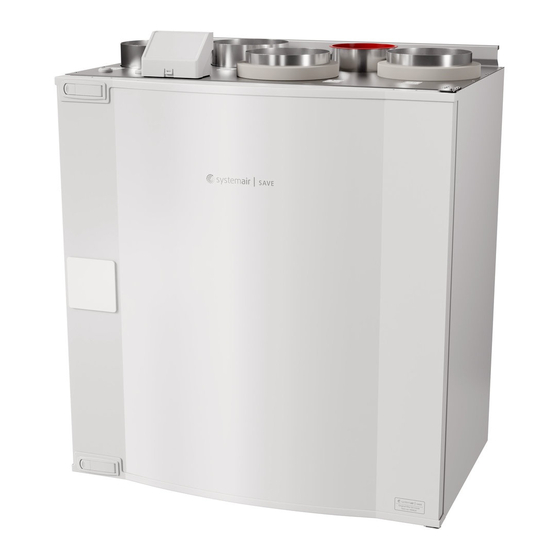
- Page 1 SAVE VTR 300/B Installation instructions Document in original language | 229391 · v02...
- Page 2 This also applies to products already ordered, as long as it does not affect the previously agreed specifications. Systemair is not liable or bound by warranty if these instructions are not adhered to during installation or service. 229391 | v02...
-
Page 3: Table Of Contents
Contents Overview ............1 Warranty ..........1 Type label..........1 Disposal and recycling ......1 Important Safety Information ......1 Intended Use.........2 Admonitions .........2 Technical Data ..........2 Power consumption and fuse size ....2 Dimensions and Weight ......3 Connections Left and Right models.....5 Installation recommendation regarding condensation ........5 3.4.1 Condensation inside of the... -
Page 5: Overview
For the assertion of warranty claims, the products must be correctly connected and operated, and used in accordance with the data sheets. Further prerequisites are a completed maintenance plan with no gaps and a commissioning re- port. Systemair will require these in the case of a warranty claim. Type label Before calling your service representative, make a note of the specification and production number from the type label, which can be found next to the external connections and inside of the unit. -
Page 6: Intended Use
| Technical Data • Safety elements may not be dismantled, circumvented or deactivated. • Wear protective equipment during all work in the vicinity of the unit. • Do not allow children to play with the device. Intended Use • Abide by the system-related conditions and requirements of the system manufacturer or plant constructor. •... -
Page 7: Dimensions And Weight
Technical Data | Dimensions and Weight Fig. 2 Dimensions of left hand unit 229391 | v02... - Page 8 | Technical Data Fig. 3 Dimensions of right hand unit * Water coil connections. ** Drainage. *** Height with mounting bracket. The unit weight is 56 kg. 229391 | v02...
-
Page 9: Connections Left And Right Models
Technical Data | Connections Left and Right models Position Description Right hand model (Supply air connection is situated on the right hand side of the unit viewed from the front) Left hand model (Supply air connection panel is situated on the left hand side of the unit viewed from the front) Description Description... -
Page 10: Condensation Outside Of The Unit
Transport and storage The SAVE VTR 300/B should be stored and transported in such a way that it is protected against physical damage. It should be covered so dust, rain and snow cannot enter and damage the unit and its components. -
Page 11: Location And Space Requirements
Access to Power supply The SAVE VTR 300/B is supplied with approximately 1,5 m cable and plug for 230V, single phase earthed connection. Make sure a power outlet is reachable by the plug. - Page 12 | Installation C — concrete/bricks, W — wood block, G — gypsum, M — mineral wool X* — adaptable height according to needs. Make sure the mounting bracket is completely level. 229391 | v02...
-
Page 13: Ventilation Duct Connection And Insulation
Before Starting the System | Follow the ventilation drawing when connecting the unit to the duct system. Ventilation Duct Connection and Insulation Important • Always cover the ventilation ducts during construction period. • Make sure there are no loose objects or impurities inside the ducts. Install the ducts, supply air diffusers and air intake grilles as shown in the ventilation drawing. -
Page 14: Commissioning
| Commissioning • The unit is correctly wired Commissioning Follow the first startup instructions and fill in the Commissioning record as you go through the settings. The Startup Wizard cannot be skipped. Select language, set the time and choose airflow control type. Select revolutions per minute as the type of airflow con- trol only if these values are included with the device. -
Page 15: Eu Declaration Of Conformity
The manufacturer hereby confirms that EN 61000-6-2 SAVE VTR 300/B Electromagnetic compatibility (EMC) – Part 6-2: Generic standards – Immunity for industrial environments. comply with all applicable requirements in the following directives and regulations. - Page 16 Systemair UAB Linų st. 101 LT–20174 Ukmergė, LITHUANIA Phone +370 340 60165 Fax +370 340 60166 www.systemair.com...
Need help?
Do you have a question about the SAVE VTR 300/B and is the answer not in the manual?
Questions and answers