Table of Contents
Advertisement
Available languages
Available languages
Quick Links
Advertisement
Table of Contents

Related Manuals for GiBiDi BE24


Summary of Contents for GiBiDi BE24
- Page 1 BE24 BE24 - (AS06250) Apparecchiatura elettronica ISTRUZIONI PER L’INSTALLAZIONE Electronic control unit INSTRUCTIONS FOR INSTALLATION Platine électronique INSTRUCTIONS POUR L’INSTALLATION Elektronische apparatuur INSTRUCTIES VOOR DE INSTALLATIE...
-
Page 2: Caratteristiche Tecniche
• Programmazione della richiusura automatica e del tempo di pausa tramite dip switch. • Predisposizione per uso con batterie tampone. • Soft-Start e Soft-Stop per limitare gli shock meccanici. Grazie per avere scelto GIBIDI. LEGGERE ATTENTAMENTE QUESTO MANUALE PRIMA DI PROCEDERE ALL’INSTALLAZIONE. AVVERTENZE: Questo prodotto è... -
Page 3: Avvertenze Per L'installazione
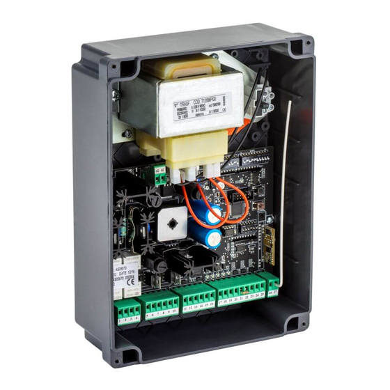
BE24 3 - AVVERTENZE PER L’INSTALLAZIONE • Prima di procedere con l’installazione bisogna predisporre a monte dell’impianto un interruttore magneto termico e differenziale con portata massima 10A. L’interruttore deve garantire una separazione omnipolare dei contatti, con distanza di apertura di almeno 3 mm. - Page 4 BE24 5 - COLLEGAMENTI ELETTRICI: FASTON FASTON Descrizione 0 Vac da trasformatore 24 Vac da trasformatore 6 - COLLEGAMENTI ELETTRICI: MORSETTIERE Morsetto Posizione Segnale Descrizione Motore 1+ Motore 1- Motore 2+ Motore 2- + Alimentazione elettroserratura 12V. - Alimentazione elettroserratura 12V.
-
Page 5: Fusibili Di Protezione
BE24 7 - FUSIBILI DI PROTEZIONE Posizione Valore Tipo Descrizione Protegge l’alimentazione batteria 24V. Protegge gli accessori esterni, l’elettroserratura e il lampeggiante 3,15A Protegge la scheda elettronica. Protegge il trasformatore. 8 - LED DI SEGNALAZIONE Posizione Colore Segnale Descrizione Si accende quando viene attivato il comando START dalla morsettiera o dalla ricevente. - Page 6 BE24 9 - DIP SWITCH DIP1 Le impostazioni vengono memorizzate durante la fase di riposo (cancello chiuso). Le impostazioni di DEFAULT sono evidenziate con lo sfondo della casella in grigio Funzione Stato Descrizione Funzionamento in risposta al comando di START : →...
- Page 7 BE24 9 - DIP SWITCH DIP1 Le impostazioni vengono memorizzate durante la fase di riposo (cancello chiuso). Le impostazioni di DEFAULT sono evidenziate con lo sfondo della casella in grigio Funzione Stato Descrizione Abilita il prelampeggio di 3 secondi prima dell’attivazione del motore in apertura e chiusura.
- Page 8 BE24 10 - DIP SWITCH DIP2 Le impostazioni vengono memorizzate durante la fase di riposo (cancello chiuso). Le impostazioni di DEFAULT sono evidenziate con lo sfondo della casella in grigio Funzione Stato Descrizione FUNZIONAMENTO ENCODER Il cambio di impostazione resetta la centrale ed è...
- Page 9 BE24 11 - JUMPER SW4 Le impostazioni vengono memorizzate durante la fase di riposo (cancello chiuso). Le impostazioni di DEFAULT sono evidenziate con lo sfondo della casella in grigio JUMPER Funzione Stato Descrizione All'ingresso STOP/COSTA (21) sono collegati dispositivi di tipo N.C.
- Page 10 BE24 13 - GESTIONE RICEVENTE RADIO A BORDO Memorizzazione nuovo trasmettitore: 1 - Premere e rilasciare il pulsante Learn. 2 - Il led L6 si accenderà 3 - Premere il tasto 1 del radiocomando da memorizzare per 2 secondi. 4 - Il nuovo radiocomando è memorizzato.
-
Page 11: Risoluzione Problemi
BE24 Movimenti eseguiti durante l’apprendimento con 2 motori: • Motore 1 apre fino ad incontrare le battute meccaniche. • Motore 2 apre fino ad incontrare le battute meccaniche. • Pausa di 5 secondi. • Motore 2 chiude fino ad incontrare le battute meccaniche. - Page 12 GI.BI.DI. S.r.l. Via Abetone Brennero, 177/B, 46025 Poggio Rusco (MN) ITALY dichiara che i prodotti: APPARECCHIATURA ELETTRONICA BE24 sono conformi alle seguenti Direttive CEE: Direttiva LVD 2006/95/CE e successive modifiche; • • Direttiva EMC 2004/108/CE e successive modifiche; e che sono state applicate le seguenti norme armonizzate: EN60335-1, •...
- Page 13 BE24 NOTE...
-
Page 14: Technical Specifications
• Programming of automatic closing and pause time via DIP switch. • Provision for use with buffer batteries. • Soft-Start and Soft-Stop to limit mechanical shock. Thank you for choosing GIBIDI. READ CAREFULLY THESE INSTRUCTIONS BEFORE PROCEEDING WITH INSTALLATION. WARNINGS: This product has been tested by GI.BI.DI. -
Page 15: Installation Warnings
BE24 3 - INSTALLATION WARNINGS • Before proceeding with installation, fit a differential magnetothermal switch with a maximum capacity of 10A upstream of the system. The switch must guarantee omnipolar separation of the contacts with an opening distance of at least 3mm. - Page 16 BE24 5 - ELECTRICAL CONNECTIONS: CONNECTORS FASTON Description 0 VAC from transformer 24 VAC from transformer 6 - ELECTRICAL CONNECTIONS: TERMINAL BOARDS Terminal Position Signal Description Motor 1+ Motor 1- Motor 2+ Motor 2- Electric lock power supply - Electric lock power supply 12V + FLASHLIGHT power supply 24 VDC MAX 10W.
-
Page 17: Protection Fuses
BE24 7 - PROTECTION FUSES Position Value Type Description Protects battery power circuit. Protects external accessories, electric lock and flashing light. 3,15A Protects the circuit board. Protects the transformer. 8 - WARNING LEDs Position Colour Signal Description Comes on when the START control is activated from the terminal board or the receiver. - Page 18 BE24 9 - DIP SWITCH DIP1 The settings are stored during the rest phase (gate closed). The default settings are highlighted in the boxes with grey background. Function Status Description Operation in response to the START command: → ŸGate closed OPENS →...
- Page 19 BE24 9 - DIP SWITCH DIP1 The settings are stored during the rest phase (gate closed). The default settings are highlighted in the boxes with grey background. Function Status Description Enables pre-flashing of 3 seconds before motor activation during opening and closing.
- Page 20 BE24 10 - DIP SWITCH DIP2 The settings are stored during the rest phase (gate closed). The default settings are highlighted in the boxes with grey background. Function Status Description FUNCTIONING ENCODER changing this setting will reset the control board and...
- Page 21 BE24 11 - JUMPER SW4 The settings are stored during the rest phase (gate closed). The default settings are highlighted in the boxes with grey background. JUMPER Function Status Description N.C. devices are connected to STOP/EDGE (21) input FUNCTIONING TERMINAL 21 8,2KOhm (8K2) resistive devices are connected to STOP/EDGE (21) input.
- Page 22 BE24 13 - ONBOARD RADIO RECEIVER CONTROL Storing a new transmitter in memory: 1 - Press and release Learn button. 2 - Led L6 will come on. 3 - Press button 1 of the transmitter to be stored for 2 seconds.
-
Page 23: Troubleshooting
BE24 Movements during learning with 2 motors: • Motor 1 opens until meeting the mechanical end-stops. • Motor 2 opens until meeting the mechanical end-stops . • 5 seconds pause. • Motor 2 closes until meeting the mechanical end-stops. • Motor 1 closes until meeting the mechanical end-stops. - Page 24 S.r.l. Via Abetone Brennero, 177/B, 46025 Poggio Rusco (MN) ITALY eclares that the products ELECTRONIC CONTROL UNIT BE24 are in conformity to the following CEE Directives Directive LVD 2006/95/CE and subsequent amendments; • • Directive EMC 2004/108/CE and subsequent amendments;...
- Page 25 BE24 NOTES...
-
Page 26: Caracteristiques Techniques
BE24 1 - CARACTERISTIQUES TECHNIQUES Platine BE24 / AS06250 Platine électronique pour l’automation d’un Type portail battant avec double porte et moteurs en 24Vdc Alimentation 230 Vac monophasé 50/60 Hz N° moteurs Alimentation moteur 24 Vdc Clignoteur 24 Vdc 10W max... -
Page 27: Instructions Pour L'installation
BE24 3 - INSTRUCTIONS POUR L’INSTALLATION • Avant d’effectuer l’installation, il faut prévoir en amont de la même un interrupteur magnétique thermique et différentiel avec capacité maxi 10A. L’interrupteur doit assurer une séparation omnipolaire des contacts, avec distance d’ouverture d’au moins 3 mm. - Page 28 BE24 5 - BRANCHEMENTS ELECTRIQUES: FASTON FASTON Description 0 Vac de transformateur 24 Vac de transformateur 6 - BRANCHEMENTS ELECTRIQUES: BORNIERS Borne Position Signal Description Moteur 1+ Moteur 1- Moteur 2+ Moteur 2- + Alimentation serrure électrique 12V. - Alimentation serrure électrique 12V.
-
Page 29: Led De Signalisation
BE24 7 - FUSIBLES DE PROTECTION Position Valeur Type Description Protection alimentation batterie 24V. Protection accessoires extérieurs, serrure électrique et clignoteur 3,15A Protection platine électronique. Protection transformateur. 8 - LED DE SIGNALISATION Position Couleur Signal Description S’allume quand on active la commande START du bornier ou du récepteur. - Page 30 BE24 9 - DIP SWITCH DIP1 Les positions sont mémorisées pendant la phase de repos (portail fermé). Les positions par DEFAUT sont indiquées dans la case grise Fonction Etat Description Fonctionnement en réponse à la commande de START : →...
- Page 31 BE24 9 - DIP SWITCH DIP1 Les positions sont mémorisées pendant la phase de repos (portail fermé). Les positions par DEFAUT sont indiquées dans la case grise Fonction Etat Description Habilite le pré-clignotement de 3 s avant l’activation du moteur en ouverture et fermeture.
- Page 32 BE24 10 - DIP SWITCH DIP2 Les positions sont mémorisées pendant la phase de repos (portail ouvert). Les positions par DEFAUT sont indiquées avec la case grise Fonction Etat Description FONCTIONNEMENT ENCODER Le changement de position met à zéro la centrale et il est nécessaire faire un nouveau...
- Page 33 BE24 11 - JUMPER SW4 Les positions sont mémorisées pendant la phase de repos (portail ouvert). Les positions par DEFAUT sont indiquées avec la case grise JUMPER Fonction Etat Description Les dispositifs N.C. sont connectées à l'entrée STOP/BORD SENSIBLE (21)
- Page 34 BE24 13 - GESTION RECEPTEUR RADIO A BORD Mémoriser un nouvel émetteur: 1 - Appuyer sur la touche Learn et la relâcher. 2 - Le led L6 s’allumera 3 - Appuyer sur la touche 1 de l’émetteur à mémoriser par 2 s.
- Page 35 BE24 Mouvements faits pendant l’apprentissage avec 2 moteurs: • Moteur 1 ouvre jusqu’à rencontrer les arrêts mécaniques. • Moteur 2 ouvre jusqu’à rencontrer les arrêts mécaniques. • Pause de 5 s • Moteur 2 ferme jusqu’à rencontrer les arrêts mécaniques.
- Page 36 BE24 Déclaration de conformité CE Le constructeur GI.BI.DI. S.r.l. Via Abetone Brennero, 177/B, 46025 Poggio Rusco (MN) ITALY éclare que le produit ci-dessous APPAREILLAGE ÉLECTRONIQUE BE24 est conforme aux Directives CEE suivantes Directive LVD 2006/95/CE et modifications successives; • • Directive EMC 2004/108/CE et modifications successives;...
- Page 37 BE24 NOTES...
-
Page 38: Technische Eigenschappen
• Voorziening voor gebruik met buffer batterijen. • Soft-Start en Soft-Stop om de mechanische schokken te beperken. Bedankt om te kiezen voor GIBIDI. LEES DEZE GEBRUIKSAANWIJZING HEEL AANDACHTIG ALVORENS DE INSTALLATIE AAN TE VATTEN. WAARSCHUWING: Dit product werd gekeurd bij GI.BI.DI. voor de naleving of de kenmerken van het product perfect overeenkomen met de geldige richtlijnen. - Page 39 BE24 3 - WAARSCHUWINGEN VOOR DE INSTALLATIE • Alvorens met de installatie te beginnen, moet u een thermomagnetische schakelaar of een differentieelschakelaar met een maximale stroomsterkte van 10A stroomopwaarts van de installatie plaatsen. De schakelaar moet een omnipolaire onderbreking van de contacten waarborgen, met openingsafstand van minstens 3 mm.
- Page 40 BE24 5 - ELEKTRISCHE AANSLUITINGEN: CONNECTOREN FASTON Beschrijving 0 VAC van transformator 24 VAC van transformator 6 - ELEKTRISCHE AANSLUITINGEN: KLEMMENBORDEN Klem Positie Signaal Beschrijving Motor 1+ Motor 1- Motor 2+ Motor 2- + Voeding elektrisch slot 12V - Voeding elektrisch slot 12V + voeding KNIPPERLICHT 24 VDC MAX 10W.
- Page 41 BE24 7 - GLASZEKERINGEN Positie Waarde Type Beschrijving Beveiliging van de batterij. Beveiliging van de bijkomende toebehoren, elektrisch slot en knipperlicht. 3,15A Beveiliging van de elektronische besturing. Beveiliging van de transformator. 8 - SIGNALERINGSLEDS Positie Kleur Signaal Beschrijving Gaat branden wanneer het START-commando wordt geactiveerd.
- Page 42 BE24 9 - DIP SWITCH DIP1 De instellingen worden opgeslagen tijdens de rustfase van de motor (tijdens gesloten poort). De standaard instellingen worden hieronder gemarkeerd met een grijze markering. Functie Status Beschrijving Werking volgend op START commando: → ŸPoort is gesloten OPENT →...
- Page 43 BE24 9 - DIP SWITCH DIP1 De instellingen worden opgeslagen tijdens de rustfase van de motor (tijdens gesloten poort). De standaard instellingen worden hieronder gemarkeerd met een grijze markering. Functie Status Beschrijving Activeert het voorknipperen voor 3 seconden vóór het starten van de motor tijdens opening en sluiting.
- Page 44 BE24 10 - DIP SWITCH DIP2 De instellingen worden opgeslagen tijdens de rustfase van de motor (tijdens gesloten poort). De standaard instellingen worden hieronder gemarkeerd met een grijze markering. Functie Status Beschrijving FUNCTIE ENCODER wijzigen van deze instelling zal de...
- Page 45 BE24 11 - JUMPER SW4 De instellingen worden opgeslagen tijdens de rustfase van de motor (tijdens gesloten poort). De standaard instellingen worden hieronder gemarkeerd met een grijze markering. JUMPER Functie Status Beschrijving Aan de ingang STOP/EDGE (21) zijn er inrichtingen van het type N.C. verbonden.
- Page 46 BE24 13 - AANLEREN VAN DE AFSTANDBEDIENINGEN Programmeren van een nieuwe afstandbediening in het geheugen: 1 - Druk op de Learn knop en laat los. 2 - Led L6 gaat branden. 3 - Druk op knop 1 van de zender voor 2 seconden om deze te programmeren.
- Page 47 BE24 Bewegingen met 2 motoren tijdens het aanleren: • Motor 1 opent tot aan de mechanische eindaanslag. • Motor 2 opent tot aan de mechanische eindaanslag. • 5 seconden pauze. • Motor 2 sluit tot aan de mechanische eindaanslag. • Motor 1 sluit tot aan de mechanische eindaanslag.
- Page 48 GI.BI.DI. S.r.l. Via Abetone Brennero, 177/B, 46025 Poggio Rusco (MN) ITALY verklaart dat de producten ELEKTRONISCHE BESTURING BE24 conform met de volgende CEE-richtlijnen zijn ichtlijn LVD 2006/95/CE en daaropvolgende wijzigingen; • R • Richtlijn EMC 2004/108/CE en daaropvolgende wijzigingen; en dat de volgende geharmoniseerde normen werden toegepast EN60335-1, •...
- Page 49 BE24 AANTEKENINGEN...
- Page 50 BE24 NOTES...
- Page 51 BE24 NOTES...
- Page 52 GI.BI.DI. S.r.l. Via Abetone Brennero, 177/B 46025 Poggio Rusco (MN) - ITALY Tel. +39.0386.52.20.11 Fax +39.0386.52.20.31 E-mail: info@gibidi.com Numero Verde: 800.290156 w w w . g i b i d i . c o m...
Need help?
Do you have a question about the BE24 and is the answer not in the manual?
Questions and answers