Table of Contents
Advertisement
Quick Links
Advertisement
Table of Contents

Related Manuals for GiBiDi AS06200


Summary of Contents for GiBiDi AS06200
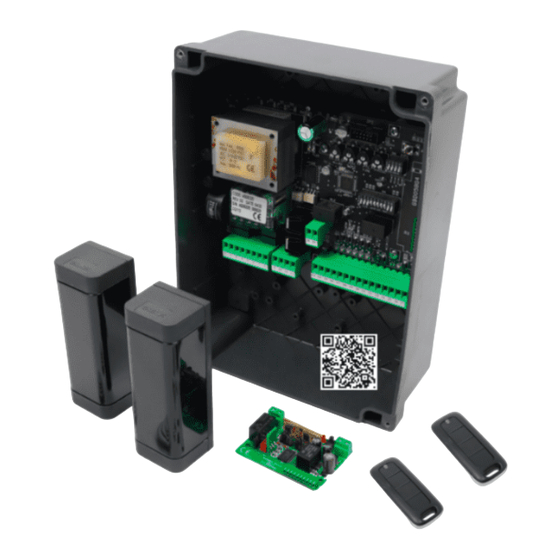
- Page 1 BR24 BR24 - (AS06200) Electronic control unit INSTRUCTIONS FOR INSTALLATION...
- Page 2 BR24 SCHEMA ELETTRICO / ELECTRICAL CONNECTION 24Vac 6/12Vac ~ 230Vac 0Vac BR24 LCD1 SYNC STOP START DL10 SLOW SLOW 24 25 26 27 28 29 30 31 32 33 34 35 36 37 22 23 LED STATUS 24 25 26 27 28 29 30 31 32 33 34 35 36 37...
- Page 3 BR24 SINCRONISMO / SYNCRONISM 0Vac 0Vac 24Vac 24Vac MOTOR MOTOR CLOSE CLOSE MOTOR MOTOR OPEN OPEN LAMP 24Vcc 10W MAX LAMP 24Vcc 10W MAX LAMP LAMP 230 Vac PHASE 230 Vac PHASE LIGHT LIGHT LIGHT LIGHT 230 Vac NEUTRAL 230 Vac NEUTRAL 24Vcc 3W MAX SPIA...
- Page 4 BR24 COLLEGAMENTO BATTERIE CON SINCRONISMO / BATTERY BACKUP CONNECTION WITH SYNCRONISM 0Vac 0Vac 24Vac CB24 24Vac CB24 MOTOR MOTOR CLOSE CLOSE MOTOR MOTOR OPEN OPEN LAMP 24Vcc 10W MAX LAMP 24Vcc 10W MAX LAMP LAMP 230 Vac PHASE 230 Vac PHASE LIGHT LIGHT...
- Page 5 BR24 OROLOGIO ESTERNO / SEMAFORO UNA VIA / EXTERNAL CLOCK ONE WAY TRAFFIC LIGHT ELECTRICAL BOX OROLOGIO ESTERNO EXTERNAL CLOCK ROSSO VERDE GREEN 16 17 18 NA NC 230Vac/24Vac-dc SEMAFORO DUE VIE / TWO WAYS TRAFFIC LIGHT ELECTRICAL BOX ROSSO/RED VERDE/GREEN INGRESSO/IN 230Vac/24Vac-dc...
- Page 6 BR24 COLLEGAMENTO FOTOCELLULE / PHOTOCELLS CONNECTION...
- Page 7 BR24 FOTO TEST / PHOTO TEST 21 22 21 22...
- Page 8 BR24 Thank you for choosing GI.BI.DI. READ CAREFULLY THESE INSTRUCTIONS BEFORE PROCEEDING WITH INSTALLATION. WARNINGS: This product has been tested by GI.BI.DI. for full compliance with the requirements of the directives in force. GI.BI.DI. S.r.l. reserves the right to change the technical data without prior notice in relation to product development. DISPOSAL: GI.BI.DI.
-
Page 9: Installation Warnings
BR24 INSTALLATION WARNINGS • Before proceeding with the installation, fit a magneto-thermal or differential switch with a maximum capacity of 10A upstream of the system. The switch must guarantee omnipolar separation of the contacts, with an opening distance of at least 3 mm. •... -
Page 10: Technical Data
BR24 TECHNICAL DATA Control unit BR24 / AS06200 Electronic control unit Type for the automation of a 24 Vdc barrier Power supply 230Vac monophase 50/60 Hz No. Motors Motor power supply 24 Vdc Flashing light 24Vdc 10W max Boom lights... - Page 11 BR24 POWER SUPPLY PHASE 230Vac for boom lights LIGHT BOOM LIGHTS 230 Vac LIGHT BOOM LIGHTS 230 Vac POWER SUPPLY NEUTRAL 230Vac for boom lights On this terminal block there is a free contact that is activated at the start of the motor and disabled after 3 s. The contact can be used to control an ELECTRIC LOCK or an ELECTROMAGNET.
-
Page 12: Signalling Led
BR24 SAFETY DEVICES input (8K2 EDGE) If not in use disable during programming (C9-1). If using a safety edge with NC contact, an 8K2 resistor must be connected in SAFETY series to one of the cables wired to the control board. Operation: Input active only during closing. -
Page 13: Protection Fuses
BR24 PROTECTION FUSES Position Value Type Description External accessories protection (accessories wired between +24 Vdc and COMMON) 500 mA FAST Control unit, motor and accessories protection when the control unit is battery supplied 15 A Control unit, motor and accessories protection 15 A CHECK ENABLED INPUT During stand by (closed barrier) the control unit perform a test to verify the consistency between the enabling of... -
Page 14: Password Management
BR24 PASSWORD MANAGEMENT You can enter the control board programming menu in 2 different ways, using 2 different password depending on which menu you want to set. BASIC MODE: when prompted for the password enter 0000. In such a way you enter only the menus listed below operation logic automatic closing... - Page 15 BR24 The second digit blinks. 0 0 0 0 If you want to enter the ADVANCED programming, by means of + or - keys type the second digit of the installer code set in the menu E92. Once you get to the desired digit confirm with the OK button and go to the next step.
- Page 16 BR24 MENU A: SYSTEM CONFIGURATION AND OPERATING LOGIC SELECTION Example Programming MENU A When the display shows the main menus (letters ACFHE or just some of them depending on which password was used to access A C F H E programming) let the letter A blink by moving to the right or to the left with the buttons + or - Once the letter A blinks confirm with the OK button...
- Page 17 BR24 WARNING: the OPEN command changes its function if you use a traffic light and select the menu E20-3. Refer to the paragraph related to the traffic light operation STEP BY STEP Command CLOSE WITH STOP LOGIC - During opening inverts the motion toward closing - During pause enables closing - Durino closing is irrelevant - With gate closed is irrelevant...
- Page 18 BR24 Command OPEN - With gate closed it opens but does not make the automatic closing - With gate closed it opens but does not make the automatic closing - During opening is irrelevant - During pause is irrelevant - During closing inverts the motion toward opening and it will not follow an automatic closing.
- Page 19 BR24 By means of + or - buttons you can select the submenus (C1, C2, C3,..) The digits on the lcd are fixed to show that is no possible any modification. C 1 1 The button ESC lets you to go to the upper level (menus A, C, F, H E). With OK button you enter the selected menu and the digits start blinking to show that is now possible to modify the values and the ESC button becomes irrelevant.
- Page 20 BR24 Enabled in closing and opening. (suggested for booms over 4m)) Operation: The closing and opening manoeuvres start with slowed motion, in this phase the slow down is obtained by the transformer. SLOWED In correspondence of the first closing/opening limit switch the slow OPENING / CLOSING down made with the transformer (JP13 close with wire) or the adjustable electronic slow down (JP13 open) starts.
- Page 21 BR24 By means of + or - buttons you can select the submenus (F2, F3, F4) The digits on the lcd are fixed to show that is no possible any modification. The button ESC lets you to go to the upper level (menus A, C, F, H E). With OK button you enter the selected menu and the value set is shown.
- Page 22 BR24 MENU H: TIME SETTINGS Example Programming MENU H When the display shows the main menus (letters ACFHE or just some of them depending on which password was used to access A C F H E programming) let the letter H blink by moving to the right or to the left with the buttons + or - Once the letter H blinks confirm with the OK button By means of + or - buttons you can select the submenus (H9)
- Page 23 BR24 Appears again menu H9. With ESC return to the upper level (menu A, C, F, H, E) Description MENU H All the times can be set in steps of 1 s Menu Fonction Description Determines the pause time in opening before automatic closing. AUTOMATIC CLOSING PAUSE TIME (t.max 300 sec.) MENU E: ENABLING AND DISABLING...
- Page 24 BR24 Example Programming MENU E From E90 When the display shows the main menus (letters ACFHE or just some of them depending on which password was used to access A C F H E programming) let the letter E blink by moving to the right or to the left with the buttons + or - Once the letter E blinks confirm with the OK button By means of + or - buttons you can select the submenus (E90, E92, …)
- Page 25 BR24 Description MENU E Menu Function Status Description Disables the photocell test Enables the photocell test. The transmitter of the photocell must be connected to the terminal n. 21 and 22 PHOTOCELL TEST Operation: When the START or OPEN command is given the power to the photocell transmitter is cut off for 0,5 s and then restored: if photocell input switches from close to open and then return close the motor starts, otherwise a fault will be signalled by 4 blinks (1 s) of the flashing light,...
- Page 26 BR24 EXTERNAL CLOCK - AUTOMATIC OPENING AND CLOSING COMMAND Enable the RESERVE input for the connection of an external clock Operation: With the contact on the RESERVE input closed between terminal 32 and common 33 (led DL8 on), an automatic opening command will EXTERNAL CLOCK activate (with no need of a START command).
- Page 27 BR24 USING THE LIMIT SWITCHES The detection of the limit switches, two in opening and two in closing, is made by means of an electronic board assembled on the operator. Such a board detects the polarity of the magnets attached on the plastic supports of the metal disc.
-
Page 28: Operation
BR24 SYNCRONIZED SYSTEM In case of installation with 2 control boards wired and syncronized with each other the MASTER will send some commands to the SLAVE, that works in sync with the MASTER. CONTROL BOARDS SETTINGS 1 - define a control board as MASTER setting the E22-2. On the display will appear the letter “m” on top left. 2 - define the other control board as SLAVE setting the menu E22-3. - Page 29 BR24 TRAFFIC LIGHT OPERATION WARNING: in the drawings n. 5 and 6 the power for the lights must be taken outside the control board. If not possible please refer to the electrical features of the control board, being careful not to overload the output power accessory.
- Page 30 BR24 BACKUP BATTERIES USE The batteries capacity should be chosen depending on the type of installation. If the installation is preset for the use of backup batteries, the amperometric thresholds and the forces must be set checking the correct operation even when the control equipment is supplied only by the batteries. When the control equipment is supplied only by the batteries, the voltage of the motor power supply is lower, thus the motor absorptions will be lower too.
- Page 31 BR24 FLASHING LIGHT SIGNALS SUMMARY Fault Signal Effect Phototest failed at opening 4 blinks 1s Blocked closed barrier Phototest failed at closing 4 blinks 1s Blocked open barrier Amperometric circuit test failed 4 blinks 2s Blocked closed barrier at opening Amperometric circuit test failed 4 blinks 2s Blocked open barrier...
-
Page 32: Default Settings
BR24 DEFAULT SETTINGS • Active parameters type A • A3 STEP - STEP WITH STOP LOGIC → • A5 AUTOMATIC CLOSING ENABLED → • Active parameters type C • C1 FAST CLOSING DISABLED → • C2 INTERMITTENT FLASHING LIGHT → •... - Page 33 EN 301 489-1 V2.2.0; EN 62479:2010; • • EN 301 489-3 V2.1.1; EN 60950-1:2014; • • EN 300 220-2 V3.2.1; • Date 13/08/2021 The legal Representative Michele Prandi UE manufacturer declaration: The UE declaration is available at http://conformity.gibidi.com...
- Page 34 GI.BI.DI. S.r.l. Via Abetone Brennero, 177/B 46025 Poggio Rusco (MN) - ITALY Tel. +39.0386.52.20.11 Fax +39.0386.52.20.31 E-mail: info@gibidi.com Numero Verde: 800.290156 w w w . g i b i d i . c o m...
Need help?
Do you have a question about the AS06200 and is the answer not in the manual?
Questions and answers