
Subscribe to Our Youtube Channel
Related Manuals for Eneo ISD-59P0010P0A


Summary of Contents for Eneo ISD-59P0010P0A
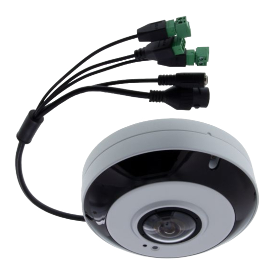
- Page 1 Quick Installation Guide 1/1,7” Network Dome, Fix, Day/Night, 4000x3000, H.265, 1.29mm, 360°, IR-LED, IP66 ISD-59P0010P0A...
-
Page 2: Table Of Contents
Contents Components........................5 Installation ........................6 Installation ...................................6 Extension Cable ................................6 Installation ..................................7 Connections ..................................8 Micro SD memory card ..............................8 Connecting to the RJ-45 ............................8 Connecting Audio ...............................8 Connecting Alarms ..............................8 Connecting the Power ..............................9 Connecting Test Monitor Out(CVBS) ........................9 Network Connection & IP Assignment ......................10 Resetting to the factory default settings......................11 Further information .................... - Page 3 Safety instructions General safety instructions • Before switching on and operating the system, first read this safety advice and the operating instructions. • Keep the operating instructions in a safe place for later use. • Installation, commissioning and maintenance of the system may only be carried out by authorised indi- viduals and in accordance with the installation instructions - ensuring that all applicable standards and guidelines are followed.
- Page 4 Class A device note This is a Class A device. This device can cause malfunctions in the living area; in such an event, the operator may need to take appropriate measures to compensate for these. WEEE (Waste Electronical & Electronic Equipment) Correct Disposal of This Product (Applicable in the European Union and other European countries with separate collection systems).
-
Page 5: Components
Components This system comes with the following components; • Dome Camera • Installation Guide • Accessory Kit NOTE: Check your package to make sure that you received the complete system, includ- ing all components listed above. NOTE: Adapter for 12 VDC is not supplied. -
Page 6: Installation
Installation Installation For the operation of the Network Camera, it is necessary to connect a network cable for data transmission, power connection from supplied power adapter. Depending on opera- tion methods, it is possible to connect an alarm cable additionally. The dome camera should be attached to a structural object, such as hard wood, wall stud or ceiling rafter that supports the weight of the dome camera. -
Page 7: Installation
Installation 1. Silicone sealant fix the rubber grommet on the bottom for water proof: 2. Make mounting holes and cable hole using the template sheet. Screw Template sheet Camera cover Dome camera Plastic anchor... -
Page 8: Connections
Connections Micro SD memory card Insert the SD card on the bottom of the dome. Connecting to the RJ-45 Connect a standard RJ-45 cable to the network port of the network camera. Generally a cross-over cable is used for directly connection to PC, while a direct cable is used for con- nection to a hub. -
Page 9: Connecting The Power
AO (Alarm Out) The camera can activate external devices such as buzzers or lights. Connect the device to the AO (Alarm Out) and G (Ground) connectors. Connecting the Power Connect power of 12VDC for the network camera. Connect the positive (+) pole to the ‘+’ position and the negative (-) pole to the ‘-’ position for the DC power. -
Page 10: Network Connection & Ip Assignment
If necessary, uncheck “DHCP”. Make the necessary settings and confirm with “OK”. The camera settings are updated. Now you can also perform a factory reset of the camera inside the eneo Site Manager. For further information, please refer to the eneo Site Manager Quick Start Guide. -
Page 11: Resetting To The Factory Default Settings
Resetting to the factory default settings To reset the network camera to the original factory settings, go to the Setup > System > Maintenance web page (described in ”System > Maintenance” of User’s Manual) or use the Reset button on the network camera inside the bottom cap. Using the Reset button: Follow the instructions below to reset the network camera to the factory default settings using the Reset button. -
Page 12: Further Information
Further information Make sure to always upgrade to the latest firmware version available from the eneo web- site at www.eneo-security.com to receive the latest functionality for your product. The manual, and other software tools are available on the eneo website at www.eneo-se- curity.com. - Page 13 Inhalt Komponenten ......................16 Installation ........................17 Installation ..................................17 Verlängerungskabel ..............................17 Installation ................................... 18 Anschlüsse ..................................19 MicroSD-Speicherkarte ............................19 Anschluss an RJ-45..............................19 Audio anschließen ..............................19 Anschließen von Alarmen ............................19 Anschluss der Stromversorgung ......................... 20 Anschließen eines Testmonitors (CVBS) ......................20 Netzwerkverbindung und IP-Zuweisung ......................
- Page 14 Sicherheitshinweise Sicherheitshinweise allgemein • Bevor Sie das System anschließen und in Betrieb nehmen, lesen Sie zuerst diese Sicherheitshinweise und die Betriebsanleitung. • Bewahren Sie die Betriebsanleitung sorgfältig zur späteren Verwendung auf. • Montage, Inbetriebnahme und Wartung des Systems darf nur durch dafür autorisierte Personen vorgenom- men und entsprechend den Installationsanweisungen - unter Beachtung aller mitgeltenden Normen und Richtlinien - durchgeführt werden.
- Page 15 • Bei abgedunkelter Umgebung und direktem Blick in den IR-Scheinwerfer ist ein Sicherheitsabstand von > 1 m zum Scheinwerfer einzuhalten. • Unsichtbare LED Strahlung nicht direkt mit optischen Instrumenten (z.B. Lupe, Vergrößerungsglas oder Mikroskop) betrachten, da sie eine Augengefährdung verursachen kann, LED Klasse 1M. •...
-
Page 16: Komponenten
Komponenten Das System wird mit den folgenden Komponenten geliefert: • Dome-Kamera • Installationsanleitung • Montageset Hinweis: Prüfen Sie den Packungsinhalt, um sicherzustellen, dass Sie das vollständige System mit allen oben genannten Komponenten erhalten haben. HINWEIS: Adapter für 12VDC ist nicht im Lieferumfang enthalten. -
Page 17: Installation
Installation Installation Zum Betrieb der Netzwerkkamera müssen ein Netzwerkkabel zur Datenübertragung und die Stromversorgung durch das mitgelieferte Netzteil angeschlossen werden. Je nach Betriebsmethode kann ein zusätzliches Alarmkabel angeschlossen werden. Die Dome-Kamera sollte an einem Bauelement wie etwa Hartholz, einem Wandständer oder Deckenbalken befestigt werden, welches das Gewicht der Kamera trägt. -
Page 18: Installation
Installation 1. Silikondichtmasse: Befestigen Sie die Gummitülle auf der Unterseite für Wasserdichtigkeit 2. Bohren Sie Befestigungslöcher und Kabelloch mithilfe der Bohrschablone. Schraube Bohrschablone Kamera-Abdeckung Dome-Kamera Kunststoffdübel... -
Page 19: Anschlüsse
Anschlüsse MicroSD-Speicherkarte Legen Sie die MicroSD-Karte auf der Unterseite der Kuppel ein. Anschluss an RJ-45 Schließen Sie ein Standard-RJ-45-Kabel an den Netzwerkanschluss der Netzwerkkamera an. Zum Anschluss an einen PC wird im Allgemeinen ein Crossover-Kabel verwendet, während zum Anschluss an einen Hub ein direktes Kabel (Patch-Kabel) verwendet wird. Zur Versorgung der Kamera mit Strom kann auch ein Router mit der PoE-Funktion (Power over Ethernet) verwendet werden. -
Page 20: Anschluss Der Stromversorgung
G (Masse) Schließen Sie die Masseseite des Alarmein- und/oder -ausgangs an den Anschluss G (Masse) an. AO (Alarmausgang) Die Kamera kann externe Geräte wie Signalhörner oder Alarmleuchten aktivieren. Schlie- ßen Sie das Gerät an die Anschlüsse AO (Alarmausgang) und G (Erdung) an. Anschluss der Stromversorgung Schließen Sie die Stromversorgung von 12 V DC an die Netzwerkkamera an. -
Page 21: Netzwerkverbindung Und Ip-Zuweisung
Netzwerkverbindung und IP-Zuweisung Mit dem eneo Site Manager können alle eneo Netzwerk Kameras im lokalen Netzwerk erkannt werden (laden Sie die Software von www.eneo-security.com herunter). Laden Sie die Software von www.eneo-security.com herunter und installieren Sie es. Starten Sie das Programm. Sie erhalten eine Liste der im lokalen Netzwerk verfügbaren Kameras. -
Page 22: Rücksetzen Auf Die Werkseinstellungen
Jetzt können Sie die Kameraeinstellungen auch mittels eneo Site Manager zurücksetzen. Weitere Informationen finden Sie im eneo Site Manager Quick Start Guide. Rücksetzen auf die Werkseinstellungen Um die Netzwerkkamera auf die Werkseinstellungen zurückzusetzen, rufen Sie die Webseite Konfiguration > System > Wartung auf (beschrieben in der Betriebsanleitung unter "System >... -
Page 23: Weitere Informationen
Bitte halten Sie die Firmware stets aktuell, damit Sie die neuesten Funktionen des Geräts nutzen können. Die aktuellsten Firmware-Versionen finden Sie auf unserer Website unter www.eneo-security.com. Das Benutzerhandbuch und weitere Software-Tools sind auf der eneo Website unter www.eneo-security.com verfügbar. Informationen zu kompatiblen Video Management Software-Lösungen finden Sie in der Kategorie Software unter www.eneo-security.com. - Page 24 Contenu Composants .........................27 Installation ........................28 Installation ..................................28 Câble d’extension ..............................28 Installation ................................... 29 Raccordements ................................30 Carte mémoire Micro SD ............................30 Connexion au RJ-45 ..............................30 Connexion audio ............................... 30 Connexion des alarmes ............................30 Connexion de l´alimentation ..........................31 Connexion de test Monitor Out (CVBS) ......................
- Page 25 Instructions de sécurité Consignes de sécurité générales • Avant de brancher et de mettre en service le système, veuillez lire d'abord ces consignes de sécurité ainsi que la notice d'instructions. • Conservez soigneusement la notice d'instructions en vue d'une utilisation ultérieure. •...
- Page 26 • Une distance de sécurité > 1 m doit être respectée par rapport au projecteur dans un environnement sombre, quand on regarde directement dans le projecteur IR. • Les rayons invisibles des LED ne doivent pas être observés directement avec des instruments optiques (par ex.
-
Page 27: Composants
Composants Le système est fourni avec les composants suivants : • Caméra dôme • Guide d'installation • Kit d'accessoires Remarque : veuillez contrôler votre package afin de vous assurer que vous avez reçu le système intégral, y compris tous les composants répertoriés plus haut. REMARQUE : L'adaptateur CC12V n'est pas fourni. -
Page 28: Installation
Installation Installation Pour utiliser la caméra réseau, il est nécessaire de brancher un câble réseau pour la trans- mission de données ainsi que la prise de courant sur le bloc d'alimentation secteur fourni. En fonction des méthodes de fonctionnement, il est également possible de connecter un câble d’alarme. -
Page 29: Installation
Installation 1. Le mastic silicone : Fixer le couvercle du dôme en le clipsant sur la base. 2. Percez les trous de fixation ainsi que le trou pour le câble à l’endroit où la caméra dôme est installée en vous référant au modèle fourni.. Gabarit de montage Cache de la caméra Caméra dôme... -
Page 30: Raccordements
Raccordements Carte mémoire Micro SD Insérez la carte SD au bas du dôme. Connexion au RJ-45 Branchez un câble RJ-45 standard au port réseau de la caméra réseau. En général, un câble croisé est utilisé pour une connexion directe à un PC alors qu’un câble direct est employé... -
Page 31: Connexion De L´alimentation
G (Ground-Terre) Connectez la mise à la terre de l’entrée de l’alarme et/ou de la sortie de l’alarme au connecteur G (terre). AO (Alarm Out - sortie alarme) La caméra peut activer des périphériques externes tels qu’un avertisseur sonore ou un signal lumineux. -
Page 32: Connexion Au Réseau Et Attribution D'une Adresse Ip
Si nécessaire, décochez « DHCP ». Ensuite, cliquez sur « OK » pour mettre à jour les ré- glages de la caméra. Maintenant, vous pouvez également effectuer une réinitialisation d'usine de la caméra à l'intérieur du eneo Site Manager. Pour plus d´informations, merci de vous référer au «... -
Page 33: Réinitialisation Aux Paramètres Par Défaut D'usine
Site Manager Quick Start Guide » (guide de démarrage rapide du gestionnaire de site eneo). Réinitialisation aux paramètres par défaut d'usine Pour réinitialiser la caméra réseau aux paramètres d'usine, suivez sur le site Internet Setup > System> Maintenance (voir le manuel de l'utilisateur « Système > Maintenance ») ou utilisez le bouton de réinitialisation sur la caméra réseau, à... -
Page 34: Complément D'information
Le manuel utilisateur et d’autres outils logiciels sont disponibles sur le site web eneo www.eneo-security.com. Des informations concernant les solutions logicielles de gestion vidéo compatibles sont disponibles dans la catégorie Software sur www.eneo-security.com. - Page 35 Indice Componenti .........................38 Installazione .........................39 Installazione ..................................39 Cavo di prolunga ............................... 39 Installazione ................................40 Collegamenti ..................................41 Alloggiamento memoria Micro SD ........................41 Collegamento a RJ-45 .............................. 41 Collegamento dell'audio ............................41 Collegamento degli allarmi ........................... 41 Collegamento dell'alimentazione ........................42 Collegamento di Test Monitor Out (CVBS) .......................
- Page 36 Istruzioni per la sicurezza Istruzioni generali per la sicurezza • Prima di collegare e mettere in funzione il sistema, leggete le istruzioni per la sicurezza e le istruzioni per l'uso. • Conservate con cura le istruzioni per l'uso per un eventuale utilizzo futuro. •...
- Page 37 • Deve essere mantenuto un margine di sicurezza di > 1 m dal proiettore se si guarda direttamente nel proiettore IR in un ambiente buio. • Non guardare direttamente le radiazioni LED invisibili utilizzando strumenti ottici (ad es. lente, lente di ingrandimento o microscopio) per prevenire danni agli occhi ( LED classe 1M).
-
Page 38: Componenti
Componenti Il sistema viene fornito con i componenti seguenti: • Telecamera dome • Guida di installazione • Kit di accessori Avviso: controllare la confezione per verificare di aver ricevuto il sistema completo, con tutti i componenti indicati sopra. NOTA: l'adattatore per 12 VCC non è fornito. -
Page 39: Installazione
Installazione Installazione Per l'utilizzo della telecamera di rete è necessario collegare un cavo di rete per la trasmis- sione dei dati e collegare l'alimentazione dall'adattatore di corrente fornito. A seconda del metodo d'uso, è possibile collegare anche un cavo di allarme. La telecamera dome deve essere fissata a un elemento strutturale, ad esempio un pezzo di legno duro, un montante o un travetto del soffitto che sostenga il peso della telecame- ra dome. -
Page 40: Installazione
Installazione 1. Il sigillante siliconico: fissa l'anello di tenuta in gomma sul fondo per impermeabilità: 2. Praticare i fori di montaggio e il foro del cavo utilizzando la dima fornita. Vite Dima Telecamera dome Coperchio della telecamera Tassello di plastica... -
Page 41: Collegamenti
Collegamenti Alloggiamento memoria Micro SD Inserire la scheda SD nella parte inferiore della dome. Collegamento a RJ-45 Collegare un cavo RJ-45 standard alla porta di rete della telecamera di rete. Generalmente si utilizza un cavo incrociato per il collegamento diretto al PC, mentre si usa un cavo di- retto per il collegamento a un hub. -
Page 42: Collegamento Dell'alimentazione
G (terra) Collegare il lato di terra dell'ingresso allarme e/o dell'uscita allarme al connettore G (terra). AO (uscita allarme) La telecamera può attivare dispositivi esterni come segnalatori acustici o luci. Collegare il dispositivo ai connettori AO (uscita allarme) e G (terra). Collegamento dell'alimentazione Collegare l'alimentazione di 12VCC della telecamera di rete. -
Page 43: Connessione Alla Rete E Assegnazione Dell'ip
Connessione alla rete e assegnazione dell'IP Lo strumento eneo Site Manager (scaricabile da www.eneo-security.com) viene utilizzato per individuare tutte le telecamere di rete eneo in una rete locale. Scarica e installa il software da www.eneo-security.com. Viene visualizzato un elenco di telecamere collegate alla rete locale. -
Page 44: Ripristino Delle Impostazioni Predefinite
Ripristino delle impostazioni predefinite Per ripristinare le impostazioni predefinite della telecamera di rete, andare alla pagina web Setup (Impostazione)>System (Sistema)> Maintenance (Manutenzione) - descritta nel manuale utente "Sistema > Manutenzione" - oppure utilizzare il tasto Reset all'interno della copertura nella parte inferiore della telecamera di rete. Utilizzo del tasto Reset: Seguire le istruzioni riportate di seguito per ripristinare le impostazioni predefinite della telecamera di rete con il tasto Reset. -
Page 45: Altre Informazioni
Il software fornito con questo prodotto contiene software protetto da copyright il cui utilizzo viene concesso con licenze open source. È possibile richiedere a Eneo il codice sorgente completo per un periodo di tre anni dopo l'ultima spedizione di questo prodotto inviando un'e-mail a: opensource@eneo-security. - Page 48 VIDEOR E. Hartig GmbH Exclusive distribution through specialised trade channels only. VIDEOR E. Hartig GmbH Carl-Zeiss-Straße 8 63322 Rödermark/Germany Tel. +49 (0) 6074 / 888-0 Technical changes reserved Fax +49 (0) 6074 / 888-100 www.videor.com...
Need help?
Do you have a question about the ISD-59P0010P0A and is the answer not in the manual?
Questions and answers