Table of Contents
Advertisement
Quick Links
Advertisement
Table of Contents

Related Manuals for Evikon PluraSens E2658-CO


Summary of Contents for Evikon PluraSens E2658-CO
- Page 1 ® PluraSens Carbon Monoxide Detector-Transmitter E2658-CO User Manual...
-
Page 2: Table Of Contents
E2658-CO Rev 06.04.2021 Table of contents Carbon Monoxide Specifications Product description Safety requirements Operating conditions Installation guidelines Mounting dimensions Sensor probe handling Gas sensor replacement procedures Electrical connections Operation Maintenance Calibration Delivery set Order code for E2658-CO options Configuring Return to default settings Modbus RTU Communication RS485 communication interface Communication parameters... -
Page 3: Carbon Monoxide
E2658-CO Rev 06.04.2021 Carbon Monoxide Carbon Monoxide is a colorless, odorless, and tasteless gas that is highly toxic. Synonyms: Carbonous oxide, Carbon (II) oxide, Flue gas, Monoxide. Chemical formula Molar weight Relative gas density (to air) 0.97 Conversion 1 ppm = 1.15 mg/m Boiling point −191.5 °C Low explosive limit (LEL), % vol. -
Page 4: Specifications
E2658-CO Rev 06.04.2021 Specifications Sensor type Electrochemical cell Sampling method Diffusion Detection range 0...300 ppm 0...1000 ppm Maximum overload 2000 ppm Resolution / digital unit 1 ppm Response time T90 < 30 s Repeatability < ± 5% Sensor lifetime > 10 years Calibration interval 12 months Signal update... - Page 5 E2658-CO Rev 06.04.2021 According to 2014/30/EU and 2014/34/EU, EN 61000-6-3:2020, EN 61326-1:2013 (EMC, Emissions) EN 61000-6-1:2019, EN 61000-6-2:2019, EN 61326-2-1:2013 (EMC, CE marking Immunity) EN 60079-0:2018, EN 60079-1:2014, EN 60079-31:2014, EN 60079-29-1:2016, EN 60079-29-2:2015, EN 60079-29-3:2014 -20...+50 °C, 0...90% RH non-condensing, 0,9...1,1 atm Explosion-safe zones and ATEX Zones 2 and 22, Operating conditions...
-
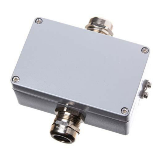
Page 6: Product Description
E2658-CO Rev 06.04.2021 Product description E2658 is a series of flameproof gas detectors-transmitters intended for operation in safe zones and ATEX Zones 2 and 22. E2658 series devices are based on PluraSens® multifunctional platform and provide all its features. The instruments utilize gas sensors of various types with excellent repeatability, stability, and long lifetime. -
Page 7: Operating Conditions
E2658-CO Rev 06.04.2021 Operating conditions The device should be used in a basic electromagnetic environment, where the latter is defined in EN 61326-1. Avoid strong mechanical shock and vibrations. Although E2658 series devices are suitable for use in the presence of flammable dust, special precautions should be taken when operating in a dusty environment. - Page 8 E2658-CO Rev 06.04.2021 The device is fixed on the wall using two fixing holes located outside the sealed area of the device (see dimensional drawing). Unscrew four lid screws and detach the lid from the detector. Fix the detector on the wall and earth the enclosure using an earthing terminal on the side of the device.
-
Page 9: Mounting Dimensions
E2658-CO Rev 06.04.2021 Mounting dimensions Front view Bottom view... -
Page 10: Sensor Probe Handling
E2658-CO Rev 06.04.2021 Sensor probe handling The sensor probes of all types are equipped with a hydrophobic microporous PTFE filter to protect the sensor from dust, dirt, and water drops. The filter should be replaced if it gets strongly contaminated. To replace the PTFE filter, unscrew the sensor head cap and remove the old filter. -
Page 11: Electrical Connections
E2658-CO Rev 06.04.2021 Electrical connections Unscrew four lid screws and detach the lid from the device. Use the M25 cable gland to let in the cables of the power supply and of the external devices. Without turning on the power, plug the power cable, and connect the analog/relay outputs and/or digital interface terminals to the necessary devices according to the relevant connection diagram. - Page 12 E2658-CO Rev 06.04.2021 The screwless quick connect spring terminals on the E2658 series devices are suitable for a wide range of wires with cross-section 0,5...1,5 mm . We recommend to strip the wire end by 8...9 mm and use the wire end sleeves. To connect the wire, insert the wire end into the terminal hole.
-
Page 13: Operation
E2658-CO Rev 06.04.2021 Operation Turn on the power. The instrument warm-up time takes about 1 minute after switching on and the final sensor stabilization time to maximum accuracy takes about 30 minutes. The operating status is indicated by the LED on the PCB of the device. The control LED (red) response to different processes is presented in the following table: Mode LED mode... -
Page 14: Delivery Set
E2658-CO Rev 06.04.2021 Delivery set ● Detector-transmitter E2658 Mounting accessories: ● 2 screws with plastic dowels ○ Order code for E2658-CO options E2658 options Order code Integrated 90...265 V mains power supply module E2658-CO-230 Integrated 24 VAC power supply module E2658-CO-24VAC Two SPST relays E2658-CO-R... -
Page 15: Configuring
E2658-CO Rev 06.04.2021 Configuring A standard configuration kit includes a USB-RS485 converter, fixed flow regulator, gas tubing with applicators, and a software pack. Please contact your Seller for more information. Detectors- transmitters E2658 share all functionalities of the PluraSens® multifunctional platform. -
Page 16: Modbus Rtu Communication
E2658-CO Rev 06.04.2021 Modbus RTU Communication RS485 communication interface Databits: 8 Supported Modbus functions: Parity: none / odd / even 03 – Read multiple registers Stop bits: 1 or 2 06 – Write a single register Protocol: Modbus RTU Communication parameters Parameter Permitted values Default... - Page 17 E2658-CO Rev 06.04.2021 0x0006 6 / 40007 RW Response delay, ms 1...255 1 – No parity bit, 1 stop bit (default after factory reset) 2 – No parity bit, 2 stop bits 3 – Odd parity, 1 stop bit 0x0007 7 / 40008 RW Stop bits, parity bit * 4 –...
- Page 18 E2658-CO Rev 06.04.2021 0 –none 211 / Parameter tied to relay 2 – gas concentration 0x00D3 40212 9 – control by Modbus control, state set in MHR / 40214 0 – none 2 – gas concentration 212 / Parameter tied to relay 0x00D4 9- –...
- Page 19 E2658-CO Rev 06.04.2021 221 / 0x00DD LOW setpoint for relay RE1 0...65535 (gas units) 40222 Specifications 222 / HIGH setpoint for relay 0x00DE 0...65535 (gas units) 40223 Specifications 223 / 0x00DF LOW setpoint for relay RE2 0...65535 (gas units) 40224 Specifications 224 / HIGH setpoint for relay...
- Page 20 E2658-CO Rev 06.04.2021 bit[11]=0/1 - 1 Hz (50% on, 50% off) LED signal off/on if relay1 turned on bit[12]=0/1 - 2 Hz (50% on, 50% off) LED signal off/on if relay2 turned on 257 / 0x0101 Raw gas sensor data 0...4095, ADC units 40258 259 /...
-
Page 21: Warranty
Manufacturer or damaged by customer error or negligence or if there has been an unauthorized modification. Manufacturer contacts Evikon MCI OÜ Teaduspargi 7/9, Tartu 50411 Estonia info@evikon.eu...
Need help?
Do you have a question about the PluraSens E2658-CO and is the answer not in the manual?
Questions and answers