
Subscribe to Our Youtube Channel
Related Manuals for Weber mt CR 7-II Hd


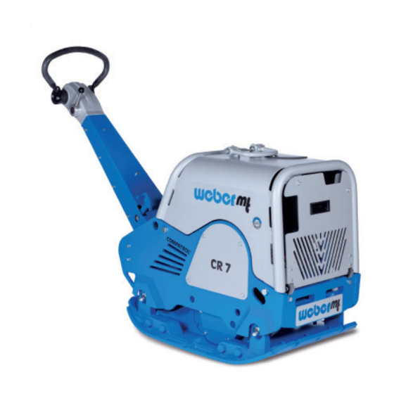
Summary of Contents for Weber mt CR 7-II Hd
- Page 1 Operating and Maintenance Manual CR 7-II Hd CR 7-II Hd E CR 7-II Hd CCD 0116641 0116642 0116645...
- Page 2 Attached to the machine is a rating plate. Note down the information given on this plate so that you can recreate the rating plate should the plate be lost. 1 Designation 2 Type ....................... 3 Serial no. 4 Year of construction ............
-
Page 3: Table Of Contents
Contents 1. Introduction ........................4 2. Description ........................5 3. Technical data ......................... 6 4. Safety ..........................7 4.1. Information and safety stickers ................12 5. Operation........................13 6. Transport ........................22 7. Storage .......................... 22 8. Maintenance ........................23 8.1. -
Page 4: Introduction
If you require any additional information, turn to your Weber MT dealer. Found on the last page of this manual is a QR code. Scan it to acquire the current contact addresses of all Weber MT branches. You can obtain information on the assembled Honda gasoline... -
Page 5: Description
2. Description The machine The machine is a hand-guided, reversible soil compactor. The machine is composed of a bottom and a top section. The bottom section houses the exciter, while the top section contains the engine and the required controls. An air-cooled Honda gasoline engine makes the exciter vibrate via a centrifugal clutch. -
Page 6: Technical Data
3. Technical data CR 7-II Hd CR 7-II Hd E CR 7-II Hd CCD Weight Operating weight CECE [kg] Dimensions Overall length [mm] 1710 1710 1710 Overall width/with attachment plates 510/650/790 510/650/790 510/650/790 [mm] 1160 1160 1160 Height with folded guide bar [mm]... -
Page 7: Safety
4. Safety General All safety instructions must be read and complied with, as non- compliance will result in - Danger to life and limb of the user, - Impairments to the machine or other property. In addition to the operating manual, the accident-prevention regulations in the country where the appliance is used must be complied with. - Page 8 Changes and conversions are prohibited unless made with conversions original Weber MT spare parts. If the machine is modified with other accessories without the approval of Weber MT, the manufacturer will not assume liability for any resulting personal injury or property damage. All maintenance and repairs must be carried out with original Weber MT spare parts. Untested spare parts may affect the...
- Page 9 Start-up procedure Do not disperse any sprays or other agents into the air intake while the machine is starting up. They may lead to overheating in the combustion chamber and result in damage to the engine. There is danger of suffocation if the operator starts up the machine in closed rooms or in deep and tight trenches. Operating the machine in closed rooms is prohibited.
- Page 10 When coming into contact with fuels, the rubber-bonded metal buffers of the machine may become damaged or ineffective. Therefore, wipe spilled fuel carefully off the rubber-bonded metal buffers. Fuel vapors are easily flammable. Do not smoke and keep away from open fire while refueling the machine. The machine must not be fueled unless the engine is switched off. Cleaning work Use clear water for cleaning. Do not use flammable solvents. The vapors of the solvents may ignite upon contact with hot components or other sparks.
- Page 11 Safety instructions and A variety of safety instructions and warnings are used warnings throughout this operating manual. The following explains the meaning of signal words and symbols. ATTENTION warns of the danger of material dam- ATTENTION age. CAUTION warns of the danger of slight injury.
-
Page 12: Information And Safety Stickers
4.1. Information and safety stickers Sticker Meaning All threaded unions must be checked for firm seat on a regular basis and, particularly, after initial use. The fuel tank may only be fueled with regular gasoline. Turn the gas cap to open and close it. Use the designated lifting ring to lift the machine. -
Page 13: Operation
5. Operation Preparing the machine for Remove all packaging material. initial use Check all components for visible damage. Do not start the machine if detecting visible damage. Contact the responsible dealer. Check if the shipment of the machine and its components is complete. - Page 14 Base plate with exciter Engine Mounting bracket Key switch Gas lever Start module Handle 10** Compaction control system Compatrol Guide bar Lifting ring *Only CR 7-II Hd E and CR 7-II Hd CCD **Only units equipped with COMPATROL compaction control.
- Page 15 The start module MS 15 Figure 2 1 Operational status indicator This indicator signals that the ignition of the machine is (LED) switched on. It comes on as soon as the key switch (5) is set to position “1”. 2 Oil pressure indicator (LED) This indicator warns of insufficient oil pressure.
- Page 16 The COMPATROL compaction control system Figure 3 1 Operational status indicator This indicator comes on as soon as the correct operating (Green) frequency has been reached and signals that the compaction control system is operational. A flashing of the indicator signifies that the machine is working with an incorrect operating frequency. 2 Compaction indicator The LEDs 1-7 indicate the achieved compaction of the soil.
- Page 17 Possible indicator states Function test of the LEDs A function test of the LEDs is performed when the ignition is turned on, but the engine has not yet been started. The operational status indicator (1) and the warning light (3) light up permanently.
- Page 18 Other damage Check and, if necessary, Engine oil correct the fill levels Hydraulic oil Fuel Other inspections Check all threaded unions for firm seat Verify compliance with the maintenance schedule Figure 4 Vandalism flap Valve box Set screw *Only CR 7-II Hd E and CR 7-II Hd CCD...
- Page 19 Start the engine only in well-ventilated environments. See section “Safety” for operating the machine in trenches. CR 7-II Hd E & CR 7-II Hd CCD Adjust the desired work height of the guide bar with the set screw (position 3, figure 4).
- Page 20 CR 7-II Hd Adjust the desired work height of the guide bar with the set screw (1). Set the short-circuit switch (2) to “I”. Open the fuel cock (slide to the right). Close the choke lever (slide to the left).
- Page 21 Bring the gas lever into the idle speed position “STOP”. Turn the ignition key (the short-circuit switch on the CR 7-II Hd) to position “0”. On the CR 7-II Hd E and the CR 7-II Hd CCD, pull out the ignition key and close the vandalism flap.
-
Page 22: Transport
3 months. Another option is to use a permanent charger / battery maintainer. If the machine is to be stored for longer than six months, contact the Weber MT’s service organization to discuss additional measures. -
Page 23: Maintenance
8. Maintenance General information The section below contains instructions that need to be observed for regular maintenance. Read these instructions carefully and follow them in order to prevent downtimes of the machine caused by excessive wear or damage to the machine. Also read the safety instructions relevant to machine maintenance before you begin with the maintenance work. -
Page 24: Maintenance Overview
8.1. Maintenance overview Frequency Activity Change the engine oil 8.2.2 Check the valve play of the en- Honda gine, adjust if necessary structions Re-tighten all accessible threaded connections Clean the air filter 8.2.3 Check the oil level of the transmis- 8.2.4 sion Change the oil in the exciter 8.2.5 Adjust / replace the spark plug 8.2.6... -
Page 25: Description Of The Maintenance Operations
8.2. Description of the maintenance operations WARNING If lubricating oils and fuel come into contact with skin, they can cause skin cancer. Wear protective gloves. If skin contact has occurred, wash the affected areas thoroughly. Park the machine on a horizontal subsurface. 8.2.1. Check the engine oil Switch off the engine and wait for several minutes until the level oil has collected in the crankcase. -
Page 26: Clean The Air Filter
Remove the cover cap from the oil drain valve. Screw the oil drain hose onto the oil drain valve. CAUTION! Danger of scalding due to hot oil. Wear protective gloves. Use extra caution. Allow the oil to drain into the collection vessel. Unscrew the oil drain pipe. -
Page 27: Check The Hydraulic Oil Level
8.2.4. Check the hydraulic oil level Lock the guide bar in place in the transport position. Check the hydraulic oil level. The oil level is correct when the oil is in the middle of the view glass. 8.2.5. Change the oil in the Start the engine and allow the engine to warm up for a few exciter minutes. -
Page 28: Check V-Belt
8.2.7. Check V-belt Shut down the machine. Remove the V-belt guard (1). Check the V-belt (2) for cracks and wear. Replace the V-belt if it shows signs of extensive wear or other damage. Fit the V-belt guard. 8.2.8. Use a permanent charger Open the maintenance cover. -
Page 29: Operating Fluids And Fill Levels
8.3. Operating fluids and fill levels Quantity Assembly Operating material Engine Engine oil SAE 10 W 40 1.1 l (-10 ~ + 50 °C) API - CD CE-CF-CG or SHPD or CCMC - D4 - D5 - PD2 Fuel tank Unleaded gasoline 6.5 l Fully-synthetic transmission fluid... - Page 32 Weber Maschinentechnik GmbH Im Boden 5-8, 10 · 57334 Bad Laasphe · Germany Phone +49 2754 398 0 · Fax +49 2754 398 101 info@webermt.de · www.webermt.de 085101306-104 / CR 7-II Hd _2020-08 Original operating manual...
Need help?
Do you have a question about the CR 7-II Hd and is the answer not in the manual?
Questions and answers