Table of Contents
Advertisement
Quick Links
Advertisement
Table of Contents

Subscribe to Our Youtube Channel
Related Manuals for Weber mt CR 7-II Hd


Summary of Contents for Weber mt CR 7-II Hd
- Page 1 Operating and Maintenance Manual CR 7-II Hd CR 7-II Hd E 0116641 0116642...
- Page 2 Attached to the machine is a rating plate. Note down the information given on this plate so that you can recreate the rating plate should the plate be lost. Description Type Serial number Year of construction Rated Mass power 1 Description 2 Type ............
-
Page 3: Table Of Contents
Contents 1. Introduction ........................4 2. Description ........................5 3. Technical data ......................... 6 4. Safety ..........................7 4.1. Information and safety stickers ................12 5. Operation........................13 6. Transport ........................21 7. Storage .......................... 21 8. Maintenance ........................22 8.1. -
Page 4: Introduction
Enclosed with this manual is a valid declaration of conformity and a spare parts lists for orders of spare parts. Store these documents carefully. Turn to your Weber MT dealer if you require any additional information. Found on the last page of this manual is a QR code. -
Page 5: Description
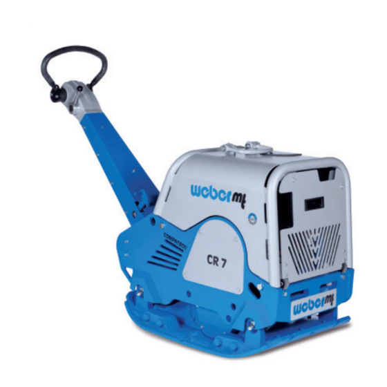
2. Description The machine The machine is a hand-guided, reversible soil compactor. The machine is composed of a bottom and a top section. The bottom section houses the exciter, while the top section contains the engine and the required controls. An air-cooled Honda gasoline engine makes the exciter vibrate via a centrifugal clutch. -
Page 6: Technical Data
3. Technical data CR 7-II Hd E Weight Operating weight CECE [kg] Dimensions Overall length [mm] 1710 Overall width / with attachment plates 510/650/790 [mm] Height with folded guide bar [mm] 1160 Base plate length [base in mm] Pressure surface [mm]... -
Page 7: Safety
4. Safety General All safety instructions must be read and complied with, as non-compliance will result in – danger to life and limb of the user, – impairments to the machine or other property. In addition to the operating manual, the accident-prevention regulations in the country where the appliance is used must be complied with. - Page 8 Spare parts, changes and Changes and conversions are prohibited unless made with conversions original Weber MT spare parts. If the machine is modified with other accessories without the approval of Weber MT, the manufacturer will not assume liability for any resulting personal injury or property damage.
- Page 9 Start-up procedure Do not disperse any sprays or other agents into the air intake while the machine is starting up. They may lead to overheating in the combustion chamber and result in damage to the engine. There is danger of suffocation if the operator starts up the machine in closed rooms or in deep and tight trenches.
- Page 10 Fueling the machine Spilled fuel may ignite and has a negative impact on the environment. Therefore, wipe up spilled fuel and make sure the gas cap is firmly tightened after fueling. Fuel vapors are easily flammable. Do not smoke and keep away from open fire while refueling the machine.
- Page 11 Inspection The machine must be inspected in accordance with the corre- sponding implementation conditions and operating conditions to ensure its operationally safe status. This inspection should be performed as needed by an expert – however, no less than once a year. The findings of the inspection must be stored in writing until the time of the next inspection.
-
Page 12: Information And Safety Stickers
4.1. Information and safety stickers Sticker Meaning All threaded unions must be checked for firm seat on a regular basis and, particularly, after initial use. The fuel tank may only be fueled with regular gasoline. Turn the gas cap to open and close it. -
Page 13: Operation
5. Operation Preparing the machine Remove all packaging material. for initial use Check all components for visible damage. Do not start the machine if detecting visible damage. Contact the responsible dealer. Check if the shipment of the machine and its components is complete. - Page 14 Overall view CR 7 Base plate with exciter Engine Mounting bracket Key switch Gas lever Start module Handle 10** Compaction control system Compatrol 2.0 Guide bar Lifting ring *Only CR 7-II Hd E *Only units equipped with COMPATROL 2.0 compaction control.
- Page 15 The start module MS 15 Figure 2 1 Operational status indicator This indicator signals that the ignition of the machine is (LED) switched on. It comes on as soon as the key switch (5) is set to position “1”. 2 Oil pressure indicator This indicator warns of insufficient oil pressure.
- Page 16 The COMPATROL compaction control system Figure 3 1 Operational status indicator This indicator comes on as soon as the operating frequency (LED) has been reached and signals that the compaction control system is operational. 2 Compaction indicator The LEDs 1 – 7 indicate the achieved compaction of the soil. (LED) If no additional LED comes on after another pass over the same spot, the maximum level of compaction has been...
- Page 17 Check and, if necessary, Engine oil correct the fill levels Hydraulic oil Fuel Other inspections Check all threaded unions for firm seat Verify compliance with the maintenance schedule Figure 4 Vandalism flap Valve box Set screw *Only CR 7-II Hd E...
- Page 18 Start the engine only in well-ventilated environments. See section “Safety” for operating the machine in trenches. CR 7-II Hd E Open the vandalism flap (position 1, figure 4) Insert the vandalism flap (1) into the designated holder on the valve box (position 2, figure 4).
- Page 19 CR 7-II Hd Adjust the desired work height of the guide bar with the set screw (1). Set the short-circuit switch (2) to “I”. Open the fuel cock (slide to the right). Close the choke lever (slide to the left).
- Page 20 Compacting CAUTION There is a crushing hazard between the machine and the wall during work in close proximity to walls. Use extra caution when working close to obstacles CAUTION Risk of injury if the machine is guided improperly. Guide the machine safely with both hands on the handle. ATTENTION Danger of material damage or excessive wear if V-belt slips through.
-
Page 21: Transport
Lightly oil all bare parts, levers and accelerator control cables. Check the charging status of the battery, recharge if necessary. If the machine is to be stored for longer than six months, contact the Weber MT’s service organization to discuss additional measures. -
Page 22: Maintenance
8. Maintenance General information The section below contains instructions that need to be observed for regular maintenance. Read these instructions carefully and follow them in order to prevent downtimes of the machine caused by excessive wear or damage to the machine. Also read the safety instructions relevant to machine maintenance before you begin with the maintenance work. -
Page 23: Maintenance Overview
8.1. Maintenance overview Frequency Activity 8.2.2 Change the engine oil Honda Check the valve play of the engine, adjust if necessary instructions Re-tighten all accessible threaded connections 8.2.3 Clean the air filter Check the oil level of 8.2.4 the transmission 8.2.5 Change the oil in the exciter 8.2.6... -
Page 24: Description Of The Maintenance Operations
8.2. Description of the maintenance operations WARNING If lubricating oils and fuel come into contact with skin, they can cause skin cancer. Wear protective gloves. If skin contact has occurred, wash the affected areas thoroughly. Park the machine on a horizontal subsurface. 8.2.1. -
Page 25: Clean The Air Filter
Remove the cover cap from the oil drain valve Screw the oil drain hose onto the oil drain valve. CAUTION! Danger of scalding due to hot oil. Wear protective gloves. Use extra caution. Allow the oil to drain into the collection vessel. Unscrew the oil drain pipe. -
Page 26: Check The Hydraulic Oil Level
8.2.4. Check the hydraulic oil level Lock the guide bar in place in the transport position. Check the hydraulic oil level. The oil level is correct when the oil is in the middle of the view glass. 8.2.5. Change the oil in Start the engine and allow the engine to warm up for the exciter a few minutes. -
Page 27: Check V-Belt
8.2.7. Check V-belt Shut down the machine. Remove the V-belt guard (1). Check the V-belt (2) for cracks and wear. Replace the V-belt if it shows signs of extensive wear or other damage. Fit the V-belt guard. 8.2.8. Use a permanent charger Open the maintenance cover. -
Page 28: Operating Fluids And Fill Levels
8.3. Operating fluids and fill levels Quantity Assembly Operating material Engine Engine oil SAE 10 W 40 1.1 l (– 10 ~ + 50 °C) API – CD CE-CF-CG or SHPD or CCMC – D4 – D5 – PD2 Fuel tank Unleaded gasoline 6.5 l Fully-synthetic transmission fluid... - Page 32 Weber Maschinentechnik GmbH Im Boden 5 – 8, 10 · 57334 Bad Laasphe · Germany Phone +49 2754 398 0 · Fax +49 2754 398 101 info@webermt.de · www.webermt.de 085101306-104 / CR 7-II Hd _2020-07 Original instructions...
Need help?
Do you have a question about the CR 7-II Hd and is the answer not in the manual?
Questions and answers