
Subscribe to Our Youtube Channel
Related Manuals for KROHNE SU 600 Ex


Summary of Contents for KROHNE SU 600 Ex
- Page 1 Operating Instructions SU 600 Ex 4 … 20 mA signal conditioning instrument Document ID: 30653...
-
Page 2: Table Of Contents
Rectify faults ........................22 Instrument repair ......................23 Dismount Dismounting steps......................24 Disposal ......................... 24 Supplement Technical data ........................ 25 Dimensions ........................27 9.3 Certificate ........................28 Editing status: 2015-01-13 SU 600 Ex • 4 … 20 mA signal conditioning instrument... -
Page 3: About This Document
This arrow indicates a single action. Sequence of actions Numbers set in front indicate successive steps in a procedure. Battery disposal This symbol indicates special information about the disposal of bat- teries and accumulators. SU 600 Ex • 4 … 20 mA signal conditioning instrument... -
Page 4: For Your Safety
During work on and with the device the required personal protective equipment must always be worn. Appropriate use SU 600 Ex is a universal signal conditioning instrument and power supply unit for connection of a 4 … 20 mA/HART sensor. You can find detailed information about the area of application in chapter "Product description". -
Page 5: Safety Label On The Instrument
DIN EN ISO 14001. Please help us fulfill this obligation by observing the environmental instructions in this manual: • Chapter "Packaging, transport and storage" • Chapter "Disposal" SU 600 Ex • 4 … 20 mA signal conditioning instrument... -
Page 6: Product Description
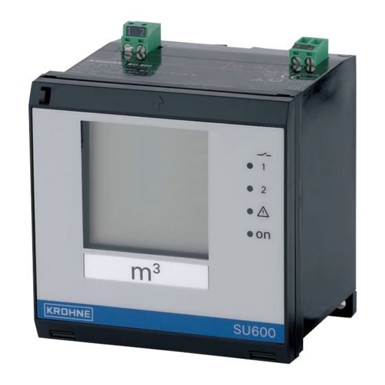
Status indication fail safe relay Status indication operation [+/-] adjustment keys 5 Insertable tag for identification of the measurement loop 6 Function switch LC display Type label The type label contains the most important data for identification and use of the instrument: • Article number • Serial number • Technical data SU 600 Ex • 4 … 20 mA signal conditioning instrument... -
Page 7: Principle Of Operation
At the same time, it can serve as power supply unit for the connected sensor.SU 600 Ex is designed for connection of any 4 … 20 mA sensor. The instrument is suitable for carrier rail, panel and surface mounting. - Page 8 Protected against solar radiation • Avoiding mechanical shock and vibration • Storage and transport Storage and transport temperature see chapter "Supplement - temperature Technical data - Ambient conditions" • Relative humidity 20 … 85 % SU 600 Ex • 4 … 20 mA signal conditioning instrument...
-
Page 9: Mounting
If the instrument is mounted via the screws or carrier rail, it must always be inside a switching cabinet or protective case. A SU 600 Ex is an auxiliary, intrinsically safe instrument and may not be installed in explosion-endangered areas. - Page 10 Metal strap 2 Covering slide switch active-passive Carrier rail mounting 1. Place the adapter plate [1] to the rear of SU 600 Ex (spring of the adapter plate downward) and fasten the plate with screw [2] (M4 x 6). 2. PlaceSU 600 Ex against the carrier rail [3] from below and push the instrument upward until it snaps in.
- Page 11 4 Mounting Fig. 4: Carrier rail mounting 1 Adapter plate Screw (M4 x 6) Carrier rail SU 600 Ex • 4 … 20 mA signal conditioning instrument...
-
Page 12: Connecting To Power Supply
If potential equalisation currents are expected, the screen connec- tion on the side of SU 600 Ex must be made via a ceramic capacitor (e. g. 1 nF, 1500 V). The low frequency potential equalisation currents are thus suppressed, but the protective effect against high frequency interference signals remains. - Page 13 2. Lead the sensor cable towards the front and out of the Ex sepa- rating chamber 3. Push the Ex separating chamber towards the front until you hear it snap in SU 600 Ex • 4 … 20 mA signal conditioning instrument...
-
Page 14: Wiring Plan
In passive mode the sensors are not powered, only the measured value is transmitted. This input is for connection of transmitters with their own separate voltage supply (sensors in four-wire ver- sion). The SU 600 Ex can be also looped into the existing circuit like a normal ammeter. The position of the slide switch also influences the preconditions for Ex implementation. Take note of the type approval certificate or the... -
Page 15: Setup With The Integrated Display And Adjustment Unit
– Current output – Integration time – Offset correction • [+/-] key: – Change value of the parameters By pushing the [+/-] key, you change the individual parameters of the selected function. In this phase, the processed parameter is flashing. SU 600 Ex • 4 … 20 mA signal conditioning instrument... -
Page 16: Setup Steps
To clearly denote the measuring unit, the supplied labels can be inserted in the cover. In case several SU 600 Ex are used, each measurement loop should be clearly labelled. Switch-on phase After being switched on, SU 600 Ex first of all carries out a short self- check. - Page 17 [1] or [2], enter the switching points for ON or OFF and save your settings. If necessary, proceed in the same way with relay 2 (position [3] or [4]). SU 600 Ex • 4 … 20 mA signal conditioning instrument...
- Page 18 In general, a period of a few seconds is sufficient to smooth the measured value display. → Now select position [9] on the function switch, enter the request- ed value and save your settings SU 600 Ex • 4 … 20 mA signal conditioning instrument...
-
Page 19: Application Example
With a reset, all values set by the user will be lost and are reset to factory settings. → Interrupt the power supply of SU 600 Ex. Push the [+/-] keys simultaneously and hold them while you switch on the power supply. The display shows "RES" and the default settings will be restored. - Page 20 0 - 20 = 0 … 20 mA • 4 - 20 = 4 … 20 mA 2. Save the value by pushing [+/-] simultaneously SU 600 Ex requires for scaling of the indication, the adjustment of the filling quantities for 0 % and 100 %. The vessel must neither be filled nor emptied. Scaled indication at 0 % 1.
- Page 21 6 Setup with the integrated display and adjustment unit Note: If you want to change the mode (i.e. the switching function of the relays), you have to exchange the On and Off values. SU 600 Ex • 4 … 20 mA signal conditioning instrument...
-
Page 22: Maintenance And Fault Rectification
– Carry out a fresh adjustment and small increase the distance between min. and max. adjustment E021 Scaling span too – Carry out a fresh scaling, increase small the distance between min. and max. scaling. SU 600 Ex • 4 … 20 mA signal conditioning instrument... -
Page 23: Instrument Repair
• Print and fill out one form per instrument • Clean the instrument and pack it damage-proof • Attach the completed form and possibly also a safety data sheet to the instrument SU 600 Ex • 4 … 20 mA signal conditioning instrument... -
Page 24: Dismount
Materials: see chapter "Technical data" If you have no way to dispose of the old instrument properly, please contact us concerning return and disposal. SU 600 Ex • 4 … 20 mA signal conditioning instrument... -
Page 25: Supplement
Contact material AG NI 0.15 hard gold-plated Switching voltage min. 10 mV DC, max. 250 V AC/DC Switching current min. 10 µA DC, max. 3 A AC, 1 A DC SU 600 Ex • 4 … 20 mA signal conditioning instrument... - Page 26 If inductive loads or stronger currents are switched through, the gold plating on the relay contact surface will be permanently damaged. The contact is then no longer suitable for switching low-level signal circuits. SU 600 Ex • 4 … 20 mA signal conditioning instrument...
-
Page 27: Dimensions
Galvanic separation between relay output and digital part Ʋ Reference voltage 250 V Ʋ Voltage resistance of the isolation 4 kV Dimensions 96 mm (3.78") 19 mm 69 mm 2 mm (0.75") (2.72") (0.08") SU 600 Ex • 4 … 20 mA signal conditioning instrument... -
Page 28: Certificate
9 Supplement 9.3 Certificate CE declarations of conformity SU 600 Ex • 4 … 20 mA signal conditioning instrument... - Page 29 9 Supplement Fig. 10: CE declarations of conformity SU 600 Ex • 4 … 20 mA signal conditioning instrument...
- Page 30 9 Supplement Trademark All the brands as well as trade and company names used are property of their lawful proprietor/ originator. SU 600 Ex • 4 … 20 mA signal conditioning instrument...
- Page 31 Integration time 16, 18 LC display 26 Line break 22 Load 26 Offset correction 16, 17 Overflow protection 17 Point level detection 17 Potential equalisation 12 Recycling 24 Relay 16, 17, 20, 23, 25 Relay output SU 600 Ex • 4 … 20 mA signal conditioning instrument...
- Page 32 Subject to change without notice 30653-EN-150129...
Need help?
Do you have a question about the SU 600 Ex and is the answer not in the manual?
Questions and answers