Table of Contents
Advertisement
Quick Links
7025282200
KROHNE 11/2007
GR
Note
In case of instruments which are explosion
please observe the supplementary
instructions:
SDA/...
Kat. II2G
installation and operating
with electr. internals
Id. Nr. 702529##00
www.krohne.com
Installation and
Operating Instructions
SDA
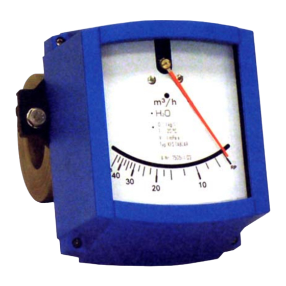
Flap-type flowmeter
for liquid measurements
Variable area flowmeters
Vortex flowmeters
Flow controllers
Electromagnetic flowmeters
Ultrasonic flowmeters
Mass flowmeters
protec
Level measuring instruments
Communications technology
Engineering systems & solutions
Switches, counters, displays and recorders
Heat metering
Pressure and temperature
Advertisement
Table of Contents

Related Manuals for KROHNE SDA


Summary of Contents for KROHNE SDA
- Page 1 7025282200 www.krohne.com KROHNE 11/2007 Installation and Operating Instructions Flap-type flowmeter for liquid measurements Variable area flowmeters Vortex flowmeters Flow controllers Electromagnetic flowmeters Ultrasonic flowmeters Mass flowmeters Note In case of instruments which are explosion protec please observe the supplementary installation and operating...
-
Page 2: Table Of Contents
Table of Contents Product liability and warranty .......................3 General............................4 Description code ..........................4 Marking ............................4 Key for Pressure Equipment Directive..................5 Functional principle........................5 Installation and Start-up........................6 Prerequisite for the installation ....................6 Preparation of the pipeline......................6 Observance of the IP degree (NEMA Type) of protection............6 Flow table............................7 Materials............................7 Technical Data..........................8... -
Page 3: Product Liability And Warranty
The calculation of the pressurized parts is effected with allowance for corrosion, erosion through abrasion or cavitation. If the flowmeter needs to be returned to KROHNE Messtechnik, please note the information at the end of these installation and operating instructions. -
Page 4: General
General Description code The description code consists of the following elements: *) Series measuring unit SDA Display part series Standard indicator with added corrosion prevention Stainless steel housing Electrical signal output Analog signal output Limit switch One limit switch Two limit switches *) Positions which are not used in the description code are not required. -
Page 5: Key For Pressure Equipment Directive
Key for Pressure Equipment Directive Pressure Equipment Directive Fluid Gases, liquefied gases, gases dissolved under pressure, vapors and those liquids whose vapor pressure lies more than 0.5 bars over the normal atmospheric pressure (1013 mbars) at the maximum permissible temperature Liquids whose vapor pressure lies a maximum of 0.5 bars above the atmospheric pressure at the maximum permissible temperature Fluid group... -
Page 6: Installation And Start-Up
Preparation of the pipeline Generally comply with the maximum pressure and maximum temperature levels allowable for the SDA at the measuring point in your plant. The direction of flow must be the same as that indicated by the flow arrow on the device. -
Page 7: Flow Table
Flow table Reference conditions: Water at 20°C The turn-down range amounts to 10 : 1 The specified pressure losses apply for water and air at the maximum flow rate. Nominal size Flow Water Inch m3/h US GPH - 12 1585 3170 1 1/4"... -
Page 8: Technical Data
Technical Data 0,5 ... 6 m Water Flow range 150 ... 1500 m Water 5% FS Accuracy min. 1 : 10 Turndown ratio DN25 ... DN300 Nominal sizes Standard PN 6/10 Max. Operating pressure Option PN 16/25/40 Standard 50 mm Mounting length Special spring 60mm... -
Page 9: Dimensions
Dimensions d4 [mm] A [mm] 232,5 236,0 240,0 245,0 252,5 260,0 270,0 282,5 295,0 320,0 345,0 370,0 395,0 420,0 485,0 530,0 Standard ring C = 50mm (Option: 60mm) -
Page 10: Indicator Part
Indicator part Contact inserts The flowmeter SDA can be equipped with a maximum of two electronic limit switches. The limit switch functions with a slot-type initiator which is operated inductively through the semicircular metal vane belonging to the measuring pointer. The switching points are set through the contact pointer. - Page 11 Connection diagram 2-wire technology NAMUR Safety-oriented * SC3,5-N0-Y SJ3,5-SN and SJ3,5-S1N Inputs Input Terminals Terminal in the in the display display Output I Output II Power Output III Output I Power LED yellow output LED green power LED yellow Relay output Switch S1 LED red LB/LK Effective direction I...
-
Page 12: Limit Setting
8.1.2 Limit setting The setting is carried out directly via the contact pointer (2): Scale opening - Slide the scale away - Loosen the locking screw (1) slightly - Slide the scale back to the latching point - Set the contact pointer (2) to the desired switching point - After setting, the contact pointer (2) is to be fastened hand-screwed again with the locking screw (1) (max. -
Page 13: Technical Data Of Limit Switches
Definition of Min1 and Min2 Max1 and Max2 current consumption with the shown pointer position SC3,5-N0 ≤1 mA Min1 Min2 SJ3,5-S1N ≤1 mA current consumption with the shown pointer position SJ3,5-S1N ≥3 mA Max1 Max2 SC3,5-N0 ≥3 mA 8.1.4 Technical data of limit switches SC3,5-N0-Y SJ3,5-SN SJ3,5-S1N... -
Page 14: Electrical Signal Output Esk
Electrical signal output ESK 8.2.1 Electrical connection The connecting terminals of the M9 display have a pluggable design and can be removed in order to connect the lines. 8.2.2 HART communication with the ESK HART communication is not compellingly required in order to operate the ESK. When HART communication is carried out with the ESK, this does not by any means impair analog measured value transfer (4...20mA) -
Page 15: Technical Data Of Esk Ii
8.2.3 Technical data of ESK II Auxiliary power 12 (18 * ) to 30 V DC Measurement signal 4.00 to 20.00 mA for 0 to 100 % flow value > 20.8 mA for alarm status Auxiliary power influence < 0.1% Dependency on external resistance <... -
Page 16: Maintenance
Maintenance The flowmeter is also to be inspected for soiling, corrosive erosion and mechanical wear or damage to the measuring tube and the display in the context of the routine operational maintenance of the installation and the pipelines. We recommend at least annual inspections. In order to clean the instrument remove it from the pipeline. Note Pressurized lines have to be relieved before the measuring unit is removed. -
Page 17: Information On Returning Instruments
- To enclose a certificate with the device confirming that This means that KROHNE can only service your device if the device is safe to handle and it is accompanied by a certificate in line with the following stating the liquid used. - Page 19 SDA Installation and operating instructions...
-
Page 20: Form For Returning The Instrument
Tel. No.: ............Fax. No.: ..............The enclosed instrument Type:................................KROHNE Order No. or Series No.: ........................ has been operated with the following process liquid: ..................Because this process liquid is water-endangering * / toxic * / caustic * / flammable *...
Need help?
Do you have a question about the SDA and is the answer not in the manual?
Questions and answers