
Related Manuals for WAGO 750-610/040-000


Summary of Contents for WAGO 750-610/040-000
- Page 1 Manual WAGO I/O SYSTEM 750 XTR 750-610/040-000 Power Supply 24 VDC Fuse Diagn XTR Power supply; 24 VDC; Fuse Holder; Diagnostics; Extreme Version 2.0.0...
- Page 2 WAGO I/O SYSTEM 750 XTR 750-610/040-000 Power Supply 24 VDC Fuse Diagn XTR © 2019 WAGO Kontakttechnik GmbH & Co. KG All rights reserved. WAGO Kontakttechnik GmbH & Co. KG Hansastraße 27 D-32423 Minden +49 (0) 571/8 87 – 0 Phone: +49 (0) 571/8 87 –...
-
Page 3: Table Of Contents
WAGO I/O SYSTEM 750 XTR Table of Contents 750-610/040-000 Power Supply 24 VDC Fuse Diagn XTR Table of Contents Notes about this Documentation ............. 5 Validity of this Documentation..............5 Copyright ....................5 Symbols ....................6 Number Notation ..................8 Font Conventions ................... - Page 4 Table of Contents WAGO I/O SYSTEM 750 XTR 750-610/040-000 Power Supply 24 VDC Fuse Diagn XTR 6.2.1 Supplementary Power Supply Regulations ........39 6.2.2 Power Supply Units ................40 Startup and Service ................41 Fuse Installation or Replacement ............41 Use in Hazardous Environments ............
-
Page 5: Notes About This Documentation
(Power Supply 24 VDC Fuse Diagn XTR). The I/O module 750-610/040-000 shall only be installed and operated according to the instructions in this manual, in the system description for the WAGO I/O SYSTEM 750 XTR and in the manual for the used fieldbus coupler/controller. -
Page 6: Symbols
Notes about this Documentation WAGO I/O SYSTEM 750 XTR 750-610/040-000 Power Supply 24 VDC Fuse Diagn XTR Symbols Personal Injury! Indicates a high-risk, imminently hazardous situation which, if not avoided, will result in death or serious injury. Personal Injury Caused by Electric Current! Indicates a high-risk, imminently hazardous situation which, if not avoided, will result in death or serious injury. - Page 7 WAGO I/O SYSTEM 750 XTR Notes about this Documentation 750-610/040-000 Power Supply 24 VDC Fuse Diagn XTR Additional Information: Refers to additional information which is not an integral part of this documentation (e.g., the Internet). Manual Version 2.0.0...
-
Page 8: Number Notation
Notes about this Documentation WAGO I/O SYSTEM 750 XTR 750-610/040-000 Power Supply 24 VDC Fuse Diagn XTR Number Notation Table 1: Number Notation Number Code Example Note Decimal Normal notation Hexadecimal 0x64 C notation Binary '100' In quotation marks, nibble separated '0110.0100'... -
Page 9: Important Notes
2.1.1 Subject to Changes WAGO Kontakttechnik GmbH & Co. KG reserves the right to provide for any alterations or modifications. WAGO Kontakttechnik GmbH & Co. KG owns all rights arising from the granting of patents or from the legal protection of utility patents. -
Page 10: Technical Condition Of Specified Devices
These modules contain no parts that can be serviced or repaired by the user. The following actions will result in the exclusion of liability on the part of WAGO Kontakttechnik GmbH & Co. KG: •... -
Page 11: 2.1.4.1.2 Packaging
WAGO I/O SYSTEM 750 XTR Important Notes 750-610/040-000 Power Supply 24 VDC Fuse Diagn XTR • Observe national and local regulations for the disposal of electrical and electronic equipment. • Clear any data stored on the electrical and electronic equipment. -
Page 12: Safety Advice (Precautions)
Important Notes WAGO I/O SYSTEM 750 XTR 750-610/040-000 Power Supply 24 VDC Fuse Diagn XTR Safety Advice (Precautions) For installing and operating purposes of the relevant device to your system the following safety precautions shall be observed: Do not work on devices while energized! All power sources to the device shall be switched off prior to performing any installation, repair or maintenance work. - Page 13 WAGO I/O SYSTEM 750 XTR Important Notes 750-610/040-000 Power Supply 24 VDC Fuse Diagn XTR Power from SELV/PELV power supply only! All field signals and field supplies connected to this XTR I/O module (750-610/040-000) must be powered from SELV/PELV power supply(s)!
- Page 14 Important Notes WAGO I/O SYSTEM 750 XTR 750-610/040-000 Power Supply 24 VDC Fuse Diagn XTR Protect the components against materials having seeping and insulating properties! The components are not resistant to materials having seeping and insulating properties such as: aerosols, silicones and triglycerides (found in some hand creams).
-
Page 15: Device Description
When configuring the system, do not exceed this current. If it is exceeded, an additional internal system supply module must be used. </dg_ The supply module (750-610/040-000) may only be used in connection with a suitable fuse (not included). </dg_ Additional information on installing or replacing a fuse is available in the section "Startup and Service"... - Page 16 Device Description WAGO I/O SYSTEM 750 XTR 750-610/040-000 Power Supply 24 VDC Fuse Diagn XTR Mixed operation Mixed operation (standard/XTR modules) within a node is possible when groups of modules are electrically isolated on the field side (i.e., electrically isolated power supply).
-
Page 17: View
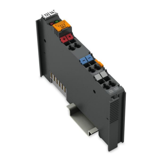
WAGO I/O SYSTEM 750 XTR Device Description 750-610/040-000 Power Supply 24 VDC Fuse Diagn XTR View Figure 1: View Table 3: Legend for Figure “View” Pos. Description Details See Section Marking possibility with Mini- “Device Description” > “Display Elements” Status LEDs “Device Description”... -
Page 18: Connectors
Device Description WAGO I/O SYSTEM 750 XTR 750-610/040-000 Power Supply 24 VDC Fuse Diagn XTR Connectors 3.2.1 Data Contacts/Local Bus Communication between the fieldbus coupler/controller and the I/O modules as well as the system supply of the I/O modules is carried out via the local bus. The contacting for the local bus consists of 6 data contacts, which are available as self-cleaning gold spring contacts. -
Page 19: Power Jumper Contacts/Field Supply
WAGO I/O SYSTEM 750 XTR Device Description 750-610/040-000 Power Supply 24 VDC Fuse Diagn XTR 3.2.2 Power Jumper Contacts/Field Supply Figure 3: Power Jumper Contacts Table 4: Legend for Figure “Power Jumper Contacts” Contact Type Function Spring contact Potential feed-in (Uv) for field supply... -
Page 20: Cage Clamp Connectors
Device Description WAGO I/O SYSTEM 750 XTR 750-610/040-000 Power Supply 24 VDC Fuse Diagn XTR ® 3.2.3 CAGE CLAMP Connectors ® Figure 4: CAGE CLAMP Connectors ® Table 5: Legend for Figure “CAGE CLAMP Connectors” Designation Connector Function 24 V... -
Page 21: Display Elements
WAGO I/O SYSTEM 750 XTR Device Description 750-610/040-000 Power Supply 24 VDC Fuse Diagn XTR Display Elements Figure 5: Display Elements Table 6: Legend for Figure “Display Elements“ Function Error status of the fuse Status voltage supply – Power jumper contacts Table 7: Display Elements –... -
Page 22: Schematic Diagram
Device Description WAGO I/O SYSTEM 750 XTR 750-610/040-000 Power Supply 24 VDC Fuse Diagn XTR Schematic Diagram Figure 6: Schematic Diagram Manual Version 2.0.0... -
Page 23: Technical Data
WAGO I/O SYSTEM 750 XTR Device Description 750-610/040-000 Power Supply 24 VDC Fuse Diagn XTR Technical Data 3.6.1 Device Data Table 8: Technical Data – Device Width 12 mm Height (from upper edge of DIN-rail) 62.6 mm Depth 100 mm Weight 46.8 mm... -
Page 24: Connection Type
Device Description WAGO I/O SYSTEM 750 XTR 750-610/040-000 Power Supply 24 VDC Fuse Diagn XTR 3.6.4 Connection Type Table 11: Technical Data – Field Wiring ® Wire connection CAGE CLAMP 0.25 mm² … 2.5 mm² / AWG 24 … 14 Cross section 8 mm …... -
Page 25: Approvals
PRS (Polski Rejestr Statków) More information about approvals. Detailed references to the approvals are listed in the document “Overview Approvals WAGO I/O SYSTEM 750”, which you can find via the internet under: DOWNLOADS Documentation System Description. www.wago.com Manual Version 2.0.0... -
Page 26: Standards And Guidelines
WAGO I/O SYSTEM 750 XTR 750-610/040-000 Power Supply 24 VDC Fuse Diagn XTR Standards and Guidelines 750-610/040-000 I/O modules meet the following standards and guidelines: Table 16: Standards and Rated Conditions for Explosion Protection Applications ATEX acc. Directive 2014/34/EU General Requirements... -
Page 27: Table 17: Climatic And Mechanical Environmental Conditions And Shipbuilding
WAGO I/O SYSTEM 750 XTR Device Description 750-610/040-000 Power Supply 24 VDC Fuse Diagn XTR Table 17: Climatic and Mechanical Environmental Conditions and Shipbuilding Standard Test Value Transport EN 60870-2-2 Ct2(2k4) (except precipitation/water/moisture) Mechanical Environmental Conditions EN 61850-3 Achieved EN 60870-2-2... -
Page 28: Table 18: Emc - Immunity To Interference
Device Description WAGO I/O SYSTEM 750 XTR 750-610/040-000 Power Supply 24 VDC Fuse Diagn XTR The I/O module 750-610/040-000 meets the following EMC standards as these standards relate to the I/O module: Table 18: EMC – Immunity to Interference Standard... - Page 29 WAGO I/O SYSTEM 750 XTR Device Description 750-610/040-000 Power Supply 24 VDC Fuse Diagn XTR Table 18: EMC – Immunity to Interference Standard Test Value Line Frequency Disturbances • EN 60255-26 Standard not applicable Alternating Components of the Voltage to DC Line Connections •...
-
Page 30: Table 19: Emc - Emission Of Interference
Device Description WAGO I/O SYSTEM 750 XTR 750-610/040-000 Power Supply 24 VDC Fuse Diagn XTR Table 19: EMC – Emission of Interference Standard Test Value Enclosure Emission of Interference • EN 61000-6-3 30 dB(µV/m), QP, 30 MHz … 230 MHz •... -
Page 31: Table 20: Standards And Rated Conditions For Rail Applications (En 50155)
EN 50121-3-2 5.5 EMC (Emission of Interference, EN 50121-3-2 Immunity to Interference) EN 50121-4 EN 50121-5 9.11 Materials (Fire Protection) EN 45545-2 Hazard level HL3 WAGO is a company certified in accordance with the IRIS quality standard. Manual Version 2.0.0... -
Page 32: Process Image
Process Image WAGO I/O SYSTEM 750 XTR 750-610/040-000 Power Supply 24 VDC Fuse Diagn XTR Process Image </dg_ Table 21: Input Bits Bit 1 Bit 0 FUSE SUPPLY SUPPLY Operating voltage monitoring The 24V power supply is not applied to the power contacts or the fuse is defective. -
Page 33: Mounting
Switch off all power to the device prior to performing any installation, repair or maintenance work. Mounting Sequence Fieldbus couplers, controllers and I/O modules of the WAGO I/O SYSTEM 750 are snapped directly on a carrier rail in accordance with the European standard EN 60175 (DIN 35). - Page 34 Always plug a bus end module 750-600/040-000 onto the end of the fieldbus node! You must always use this bus end module at all fieldbus nodes with the WAGO I/O SYSTEM 750 XTR fieldbus couplers/controllers to guarantee proper data transfer.
-
Page 35: Inserting And Removing Devices
WAGO I/O SYSTEM 750 XTR Mounting 750-610/040-000 Power Supply 24 VDC Fuse Diagn XTR Inserting and Removing Devices Do not touch hot surfaces! The surface of the housing can become hot during operation. If the device was operated at high ambient temperatures, allow it to cool off before touching it. -
Page 36: Figure 8: Snap The I/O Module Into Place (Example)
Mounting WAGO I/O SYSTEM 750 XTR 750-610/040-000 Power Supply 24 VDC Fuse Diagn XTR Press the I/O module into the assembly until the I/O module snaps into the carrier rail. Figure 8: Snap the I/O Module into Place (Example) With the I/O module snapped in place, the electrical connections for the data contacts and power jumper contacts (if any) to the fieldbus coupler/controller or to the previous or possibly subsequent I/O module are established. -
Page 37: Removing The I/O Module
WAGO I/O SYSTEM 750 XTR Mounting 750-610/040-000 Power Supply 24 VDC Fuse Diagn XTR 5.2.2 Removing the I/O Module Remove the I/O module from the assembly by pulling the release tab. Figure 9: Removing the I/O Module (Example) Electrical connections for data or power jumper contacts are disconnected when removing the I/O module. -
Page 38: Connect Devices
Only one conductor may be connected to each CAGE CLAMP Do not connect more than one conductor at one single connection! If more than one conductor must be routed to one connection, these must be connected in an up-circuit wiring assembly, for example using WAGO feed- through terminals. ®... -
Page 39: Power Supply Concept
750-624/040-001 filter module (24 VDC HI NC XTR Field Supply Filter) for filtering the 24 VDC field supply. When the internal system supply module with fuse 750-610/040-000 (Power Supply 24 VDC Fuse Diagn XTR) described here is used, the 750-624/040-000 filter module (24 VDC HI NC XTR Field Supply Filter) must be connected directly after it. -
Page 40: Power Supply Units
Connect Devices WAGO I/O SYSTEM 750 XTR 750-610/040-000 Power Supply 24 VDC Fuse Diagn XTR Pos: 64 /Serie 750 (WAGO-I/O -SYSTEM)/ Syste mbeschre ibung/Versorgung/Netzgeräte XTR @ 16\mod_1373963895846_21.docx @ 126216 @ 3 @ 1 6.2.2 Power Supply Units The WAGO I/O SYSTEM 750 XTR requires 24 VDC voltage (system supply) for operation. -
Page 41: Startup And Service
WAGO I/O SYSTEM 750 XTR Startup and Service 750-610/040-000 Power Supply 24 VDC Fuse Diagn XTR </dg_ Startup and Service </dg_ Install a new, suitable fuse before initial startup or if the fuse is defective. Only uses fuses with the specification 5 × 20 mm, T 6.3 A. -
Page 42: Figure 13: Opening The Fuse Holder
Startup and Service WAGO I/O SYSTEM 750 XTR 750-610/040-000 Power Supply 24 VDC Fuse Diagn XTR Pivot cover down to open the fuse holder. Figure 13: Opening the Fuse Holder Remove the old fuse (if any) and install the new fuse. -
Page 43: Use In Hazardous Environments
750-610/040-000 Power Supply 24 VDC Fuse Diagn XTR Use in Hazardous Environments The WAGO I/O SYSTEM 750 (electrical equipment) is designed for use in Zone 2 hazardous areas and shall be used in accordance with the marking and installation regulations. -
Page 44: Marking Configuration Examples
Use in Hazardous Environments WAGO I/O SYSTEM 750 XTR 750-610/040-000 Power Supply 24 VDC Fuse Diagn XTR Marking Configuration Examples 8.1.1 Marking for Europe According to ATEX and IECEx Figure 15: Marking Example According to ATEX and IECEx Figure 16: Text Detail – Marking Example According to ATEX and IECEx Manual Version 2.0.0... -
Page 45: Table 22: Description Of Marking Example According To Atex And Iecex
WAGO I/O SYSTEM 750 XTR Use in Hazardous Environments 750-610/040-000 Power Supply 24 VDC Fuse Diagn XTR Table 22: Description of Marking Example According to ATEX and IECEx Marking Description TUEV 07 ATEX 554086 X Approving authority resp. certificate numbers IECEx TUN 09.0001 X... -
Page 46: Figure 17: Marking Example For Approved Ex I I/O Module According To Atex And Iecex
Use in Hazardous Environments WAGO I/O SYSTEM 750 XTR 750-610/040-000 Power Supply 24 VDC Fuse Diagn XTR Figure 17: Marking Example for Approved Ex i I/O Module According to ATEX and IECEx Figure 18: Text Detail – Marking Example for Approved Ex i I/O Module According to ATEX and... -
Page 47: Table 23: Description Of Marking Example For Approved Ex I I/O Module According To Atex And Iecex
WAGO I/O SYSTEM 750 XTR Use in Hazardous Environments 750-610/040-000 Power Supply 24 VDC Fuse Diagn XTR Table 23: Description of Marking Example for Approved Ex i I/O Module According to ATEX and IECEx Marking Description TUEV 12 ATEX 106032 X Approving authority resp. -
Page 48: Marking For The United States Of America (Nec) And Canada (Cec)
Use in Hazardous Environments WAGO I/O SYSTEM 750 XTR 750-610/040-000 Power Supply 24 VDC Fuse Diagn XTR 8.1.2 Marking for the United States of America (NEC) and Canada (CEC) Figure 19: Marking Example According to NEC Figure 20: Text Detail – Marking Example According to NEC 500... -
Page 49: Figure 21: Text Detail - Marking Example For Approved
WAGO I/O SYSTEM 750 XTR Use in Hazardous Environments 750-610/040-000 Power Supply 24 VDC Fuse Diagn XTR Figure 21: Text Detail – Marking Example for Approved Ex i I/O Module According to NEC 505 Table 25: Description of Marking Example for Approved Ex i I/O Module According to NEC 505... -
Page 50: Figure 23: Text Detail - Marking Example For Approved
Use in Hazardous Environments WAGO I/O SYSTEM 750 XTR 750-610/040-000 Power Supply 24 VDC Fuse Diagn XTR Figure 23: Text Detail – Marking Example for Approved Ex i I/O Modules According to CEC 18 attachment J Table 27: Description of Marking Example for Approved Ex i I/O Modules According to CEC 18... -
Page 51: Installation Regulations
WAGO I/O SYSTEM 750 XTR Use in Hazardous Environments 750-610/040-000 Power Supply 24 VDC Fuse Diagn XTR Installation Regulations For the installation and operation of electrical equipment in hazardous areas, the valid national and international rules and regulations which are applicable at the installation location must be carefully followed. - Page 52 Use in Hazardous Environments WAGO I/O SYSTEM 750 XTR 750-610/040-000 Power Supply 24 VDC Fuse Diagn XTR Explosive atmosphere occurring simultaneously with assembly, installation or repair work must be ruled out. Among other things, these include the following activities •...
-
Page 53: Special Notes Regarding Ansi/Isa Ex
WAGO I/O SYSTEM 750 XTR Use in Hazardous Environments 750-610/040-000 Power Supply 24 VDC Fuse Diagn XTR 8.2.2 Special Notes Regarding ANSI/ISA Ex For ANSI/ISA Ex acc. to UL File E198726, the following additional requirements apply: • Use in Class I, Division 2, Group A, B, C, D or non-hazardous areas only •... -
Page 54: List Of Figures
List of Figures WAGO I/O SYSTEM 750 XTR 750-610/040-000 Power Supply 24 VDC Fuse Diagn XTR List of Figures Figure 1: View ....................17 Figure 2: Data Contacts ..................18 Figure 3: Power Jumper Contacts ..............19 ® Figure 4: CAGE CLAMP Connectors ..............20 Figure 5: Display Elements.................21... -
Page 55: List Of Tables
WAGO I/O SYSTEM 750 XTR List of Tables 750-610/040-000 Power Supply 24 VDC Fuse Diagn XTR List of Tables Table 1: Number Notation ................... 8 Table 2: Font Conventions .................. 8 Table 3: Legend for Figure “View” ..............17 Table 4: Legend for Figure “Power Jumper Contacts” ........19 Table 5: Legend for Figure “CAGE CLAMP... - Page 56 Pos: 75 /Do kumentation allgemein/Einband/E inband Rüc kseite - alle Do kumente; CI 201 7 @ 28\mod_148 647750 3580_2 1.docx @ 4053 94 @ @ 1 WAGO Kontakttechnik GmbH & Co. KG • Postfach 2880 D - 32385 Minden Hansastraße 27 • D - 32423 Minden +49 571 887 –...
Need help?
Do you have a question about the 750-610/040-000 and is the answer not in the manual?
Questions and answers