
Related Manuals for Whelen Engineering Company WAT OR5001V


Summary of Contents for Whelen Engineering Company WAT OR5001V
- Page 1 ANTI-COLLISION LIGHT SYSTEMS INSTALLATION AND SERVICE MANUAL MARCH 2019 Approved under STC SA6NE STC SA21NE STC SA615EA STC SA800EA ISO 9001 Registered QMS © 2019 Whelen Aerospace Technologies 12948E_5/2019_Document #05131 Rev. E...
-
Page 2: Table Of Contents
INDEX PAGE NUNBER 42-43 Strobe Lighthead Assemblies - A470A Series, Models A450, H102, H103 Table Of Contents/Company Information 44-45 Strobe Lighthead Assemblies - A650PG/PR Series Strobe System Requirements 46-47 LED Light Assemblies - 71110( ) Series Aircraft not specifically mentioned on the eligibility list Strobe Lighthead Assemblies - A610 Series / A612 Series Strobe System Wiring Strobe Lighthead Assemblies - A625 Series... - Page 3 INTRODUCTION TO WHELEN AEROSPACE TECHNOLOGIES POSITION LIGHTS AND ANTI-COLLISION LIGHT ANTI-COLLISION STROBE LIGHTING SYSTEMS, STC SA800EA/ DISTRIBUTION PATTERNS REQUIREMENTS STC SA615EA/STC SA6NE/ STC SA21NE Whelen Aerospace Technologies Anti-Collision Strobe Light Systems are º º º approved under STC SA615EA, STC SA800EA, STC SA6NE, and STC SA21NE, º...
-
Page 4: Aircraft Not Specifically Mentioned On The Eligibility List
AIRCRAFT NOT SPECIFICALLY MENTIONED ON THE ELIGIBILITY LIST ANTI-COLLISION LIGHT INSTALLATION PROCEDURES ESTABLISHING SOLID ANGLE BLOCKAGE WITH REFERENCE TO AC 43.13-2A, CHAPTER 4. STC SA800EA / STC SA615EA / STC SA21NE 1. To determine the vertical angles to use with reference to Figure 7 The following information is to assist in the installation of a custom and 8 of the aforementioned chapter 4, attach a long string to the Whelen anti-collision strobe light system on any aircraft, and how to... -
Page 5: Strobe System Wiring
STROBE SYSTEM WIRING Interconnecting Cable Intermixing Strobe Light System Equipment 1. The Whelen interconnecting cable shall be secured in place with Observe Color and Pin Numbers approved aviation techniques. Cables Connecting Strobe Lights MUST BE Connected 2. The cable shall not parallel ADF, Gyro or Flux Gate compass Correctly! leads closer than 12 inches. -
Page 6: Strobe Power Supply Installation
STROBE POWER SUPPLY INSTALLATION INSTALLATION PROCEDURES: Wiring WARNING!!! STROBE LIGHT POWER SUPPLIES ARE Location POLARITY SENSITIVE. REVERSING THE INPUT POLARITY WILL CAUSE SEVERE DAMAGE TO THE 1. Consider areas or locations designated by the aircraft man- POWER SUPPLY! ufacturer. Do not mount the strobe power supply closer than three (3) feet of the ADF loop. -
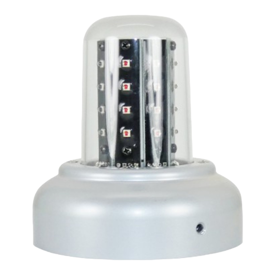
Page 7: Orion 500 Led Light Assemblies
ORION 500 LED LIGHT ASSEMBLIES MODEL OR5001V & OR5002V LED Tail Position / Anti-Collision Lighthead Assembly All LED self-contained tail mounted Position/Anti-Collision system. Eliminates the need for external power supplies and reduces current draw and provides thousands of hours of operation. Model OR500 Specifications Anti- Model... - Page 8 ORION Model OR5001V 12V Series Exploded View Parts CAUTION! DO NOT TOUCH THE LED LENS SURFACE WITH EITHER FINGERS OR SHARP OBJECTS. THIS COULD SOIL AND/OR DAMAGE THE LENS EFFECT OPTICAL PERFORMANCE OF THE LEDs Model OR5001V Parts List ITEM PART NUMBER DESCRIPTION 01-0771774V01...
-
Page 9: Orion 650 Led Light Assemblies
ORION 650 LED LIGHT ASSEMBLIES MODELS OR6501G, OR6501R, OR6502G, OR6502R LED Wingtip Position / Anti-Collision Lighthead Assembly All LED self-contained wingtip mounted Position/Anti-Collision system. Eliminates the need for external power supplies and reduces current draw and provides thousands of hours of operation. Model OR650 Specifications Anti- Model... - Page 10 Model OR6501G, OR6501R 14V Series Model OR6502G, OR6502R 28V Series Exploded View Parts Exploded View Parts Lens P/N 01-0251094-00 Shown For ReferenceOnly Drain Hole Drain Hole Model OR6501G & OR6501R Series Parts List Model OR6502G & OR6502R Series Parts List ITEM PART NUMBER DESCRIPTION...
-
Page 11: Orion 650E Led Light Assemblies
ORION 650E LED LIGHT ASSEMBLIES MODELS OR6501GE, OR6501RE, OR6502GE, OR6502RE LED Wingtip Position / Anti-Collision Lighthead Assembly All LED self-contained wingtip mounted Position/Anti-Collision system. Eliminates the need for external power supplies and reduces current draw and provides thousands of hours of operation. Model OR650E Specifications Anti- Model... - Page 12 Model OR6501GE, OR6501RE 12V Series Exploded View Parts Model OR6501GE, OR6501RE Series Parts List ITEM PART NUMBER DESCRIPTION — 01-0790701-01 OR6501GE Wingtip Position/Anti-Collision Light, 12V (Green) — 01-0790701-02 OR6501RE Wingtip Position/Anti-Collision Light, 12V (Red) 07-771790-100 Mounting Plate, Model 90701 (Heli-Coils, CMPL) —...
- Page 13 MODEL HDACF STROBE POWER SUPPLY ASSEMBLY FAA/PMA APPROVED Specifications Model Number ..HDACF Part Number ..01-0770028-05 Current Draw ..7.0 Amps @ 14 VDC 3.5 Amps @ 28 VDC Weight .
- Page 14 Pin 1. (Top) - RED wire/anode .080” Pin 2. (Center) - BLACK wire/cathode (2mm) Pin 3. (Bottom) - WHITE wire/trigger WHELEN ENGINEERING COMPANY CHESTER, CONNECTICUT 06412-0684 Right Connector (Power Input) OUTPUT POWER (1) ANODE (1) + (2) CATHODE (2) - Pin 1.
- Page 15 MODEL A490TCF STROBE POWER SUPPLY FAA/PMA APPROVED Model Number ..A490TCF Part Number ..01-0770006-08 MODEL A490TCCF STROBE POWER SUPPLY FAA/PMA APPROVED Model Number ..A490TCCF Part Number .
- Page 16 LED LIGHT ASSEMBLIES MODEL OR36( ) SERIES LED FLASHING BEACON TSO-C96a CLASS III (Red & White LED’s) APPROVED ORION 360 Beacons are the 4th Generation LED beacons for fixed wing aircraft. These are designed to replace legacy 2.6" and 3.75" round beacons.
- Page 17 INSTALLATION PROCEDURES: 7. A flight check should be performed by a properly certified pilot. 8. If required, update aircraft records utilizing FAA Field Approval (Form 337) or equivalent. Models OR36R2W, OR36R2WL Dimensions Exploded View Parts Ø3.67 Model OR36R2W & OR36R2WL1 Parts List ITEM PART NUMBER DESCRIPTION...
- Page 18 Models OR36S2W, OR36S2WL Dimensions Exploded View Parts Model OR36S2W & OR36S2WL Parts List Ø3.67 ITEM PART NUMBER DESCRIPTION 01-0772010-32 MODEL, OR36S2W 28V UPPER SPLIT 3.7” ACL 01-0772010-33 MODEL, OR36S2WL 28V LOWER SPLIT 3.7” ACL MS24693C28 SCREW, 6-32 X 1/2 P100FH/CSNK —...
- Page 19 Models OR36R1W, OR36S1W Dimensions Exploded View Parts Ø3.67 Model OR36R1W & OR36S1W Parts List ITEM PART NUMBER DESCRIPTION 01-0772010-72 MODEL, OR36S1W 14V UPPER SPLIT 3.7” ACL 01-0772010-52 MODEL, OR36R1W 14V UPPER RED 3.7” ACL MS24693C28 SCREW, 6-32 X 1/2 P100FH/CSNK 22-0472012-00 CAP, LED A/C BEACON 38-0231522-01...
- Page 20 Models OR36W2W, OR36W2WL Dimensions Exploded View Parts Model OR36W2W & OR36W2WL Parts List Ø3.67 ITEM PART NUMBER DESCRIPTION 01-0772010-22 MODEL, OR36W2W 28V UPPER WHITE 3.7” ACL 01-0772010-23 MODEL, OR36W2WL 28V LOWER WHITE 3.7” ACL MS24693C28 SCREW, 6-32 X 1/2 P100FH/CSNK —...
- Page 21 Models OR36R1N, OR36S1N Exploded View Parts Dimensions Ø2.60 Ø2.60 Ø2.60 Model OR36R1N & OR36S1N Parts List ITEM PART NUMBER DESCRIPTION 01-0772010-50 MODEL, OR36R1N 14V UPPER RED 2.6” ACL 01-0772010-70 MODEL, OR36S1N 14V UPPER SPLIT 2.6” ACL MS24693C28 SCREW, 6-32 X 1/2 P100FH/CSNK 22-0472012-00 CAP, LED A/C BEACON 38-0231522-01...
- Page 22 Models OR36R2N, OR36W2N, OR36S2N Exploded View Parts Dimensions Ø2.60 Ø2.60 Model OR36R2N, OR36W2N & OR36S2N Parts List Ø2.60 ITEM PART NUMBER DESCRIPTION 01-0772010-10 MODEL, OR36R2N 28V UPPER RED 2.6” ACL 01-0772010-20 MODEL, OR36W2N 28V UPPER WHITE 2.6” ACL 01-0772010-30 MODEL, OR36S2N 28V UPPER SPLIT 2.6” ACL MS24693C28 SCREW, 6-32 X 1/2 P100FH/CSNK 22-0472012-00...
- Page 23 LED LIGHT ASSEMBLIES CHROMA SERIES LED POSITION LAMPS TSO-C30c TYPE I & TYPE II APPROVED Meet all FAR requirements for Chromaticity, Intensity, and Coverage FAR Part 23.1383 the 23.1397 FAR Part 27.1383 thru 27.1397 Unique reflector design allows for full FAR coverage compliance. Fixed current source design provides consistent light output compared to filament lamps and LED resistor type designs = complete FAR compliance.
- Page 24 LED LIGHT ASSEMBLIES MODEL 90520( ) SERIES LED FLASHING BEACON (Red & White LED’s) TSO-C96a CLASS III APPROVED 90520 series LED beacons are FAA TSO compliant self-contained LED anti-collision lights (Ref. Class III - 100 effective candlepower). They are designed to replace strobe lightheads as small as the A470A with available models to replace HR self-contained beacons (HRCFA) or our legacy 70900 LED beacon.
- Page 25 Models 9052001, 9052051 Dimensions Exploded View Parts 2.60” (66mm) Model 9052001 & 9052001 Parts List ITEM PART NUMBER DESCRIPTION — 01-0790520-01 Model 9052001 (28V) — 01-0790520-51 Model 9052051 (14V) 07-771051-100 Adapter Plate, 8 Hole — 01-0290522-00 Assy, 28V NOTE: — 01-0290522-50 Assy, 14V RED LEDs TO THE FRONT...
- Page 26 Models 9052004, 9052014 Dimensions Exploded View Parts 5.14” (131mm) Model 9052004 & 9052014 Parts List 2.60” (66mm) ITEM PART NUMBER DESCRIPTION — 01-0790520-04 Model 9052004 (28V) Upper — 01-0790520-14 Model 9052014 (28V) Lower 01-0290522-00 Assy, 28V 38-0250885-00 Gasket, Lens — 68-4971082A30 Lens, Clear —...
- Page 27 Models 9052005, 9052015, 9052055 Dimensions Exploded View Parts 3.60” ITEM PART NUMBER DESCRIPTION (91mm) — — 01-0790520-05 Model 9052005 (28V) Upper — — 01-0790520-15 Model 9052015 (28V) Lower — — 01-0790520-55 Model 9052055 (14V) Upper 01-0290522-00 Assy, 28V — — 01-0290522-50 Assy, 14V 38-0250885-00...
- Page 28 Models 9052007, 9052017 Dimensions Exploded View Parts 3.60” ITEM PART NUMBER DESCRIPTION (91mm) — 01-0790520-07 Model 9052007 (28V) Upper — 01-0790520-17 Model 9052017 (28V) Lower 01-0290522-00 Assy, 28V 38-0250885-00 Gasket, Lens — 68-4971082A30 Lens, Clear — 68-4971082A31 Lens, Clear 07-571361-100 Adapter, Mounting NOTE: RED LEDs...
- Page 29 Models 9052008, 9052018 Dimensions Exploded View Parts 5.14” (131mm) 2.60” ITEM PART NUMBER DESCRIPTION (91mm) — 01-0790520-08 Model 9052008 (28V) Upper — 01-0790520-18 Model 9052018 (28V) Lower 01-0290522-00 Assembly, 28V 38-0250885-00 Gasket, Lens — 68-4971082A30 Lens, Clear — 68-4971082A31 Lens, Clear with Drain 38-0250225-00 Seal 07-571304-100...
- Page 30 LED LIGHT ASSEMBLIES MODEL 71080 ( ) SERIES LED BEACON (Red LED’s) LED Flashing Anti-Collision Light Assembly (150 eff. Cd) (14 VDC & 28 VDC) Anti-Collision 71080 series LED beacons are FAA TSO compliant Self-Contained LED lights (Ref. Class I - 150 effective candlepower). They are designed to replace a range of products. Refer to models and descriptions below.
- Page 31 Models 7108001, 7108006, 7108051 4x #6-32 Mounting Holes Equally 4x #6-32 Mtg Holes Equally Ø1.00 Ø1.00 Spaced on a Ø1.625 Bolt Circle Spaced on a Ø1.750 Bolt Circle Exploded View Parts Suggested Suggested 14V Mounting 28V Mounting Hole Pattern(s) Hole Pattern Mounting 4x #6-32 Mounting...
- Page 32 Models 7108004, 7108014 Dimensions Exploded View Parts 5X Ø.156 Thru Suggested Mounting Pattern C'SINK to Ø.281 x 100° spaced as shown on 75° Ø4.656 Bolt Circle 75° 60° 75° Mounting 75° ∅.125 Drain Hole Lower Mount ∅5.14” Only Ø2.60” (131mm) (66mm) 2.73”...
- Page 33 Models 7108007, 7108017 Exploded View Parts Dimensions Ø3.67” (93mm) ∅.125 (3mm) DRAIN HOLE LOWER MNT ONLY Mounting 3x #6-32 Mounting Holes 6-32 x 5/16” Suggested Screw Length 115° 3.92”±.06 (100mm) 130° 3x #6-32 5.43”±.06 HELI-COIL (138mm) insert 115° Mfg. Label Suggested Mounting Pattern Connector...
- Page 34 Models 7108008, 7108018 Dimensions Exploded View Parts ∅.125” (3mm) ∅5.14” (131mm) Drain Hole Lower Mount Only 75° 75° 17° 75° 75° Mounting 5x Ø.156” (4mm) thru C'SINK to Ø.281” (7mm) x 100° spaced as shown on Ø4.656” (118mm) Bolt Circle 75°...
- Page 35 Models 7108020, 7108030 Dimensions Exploded View Parts 5.55” (141mm) Wiring Diagram -30 Wiring Diagram 2.25” WHITE 2.70” (57mm) BLACK +28VDC (69mm) MODULE MS Connector Wiring (Rear View) Mounting 01-0771080-20 2.475” 2.475” (63mm) (63mm) ∅ .218” (6mm) .700” (18mm) 3.74”±.06 .700” (95mm) (18mm) Suggested Mounting Pattern...
-
Page 36: Self Contained Light Assemblies - 71055( ) Series
SELF CONTAINED LIGHT ASSEMBLIES MODEL 70900 ( ) SERIES TSO-C96a CLASS III APPROVED FLASHING ANTI-COLLISION LIGHT ASSEMBLY 70900 series are FAA TSO compliant self-contained anti-collision lights for fixed wing aircraft. An external power unit is not required. Conservative lab life results greater than 20,000 hours. No EMI or RFI produced. All units meet the minimum requirements stated in FAR Parts 23 &... - Page 37 Models 7090004, 7090005 Exploded View Parts Lens P/N: 68-4990257-30 Screw Before LED installation P/N: 14-062216-05M Gasket P/N: 38-0250843-00 Model 70900 series after LED installation LED Module P/N (14V): 01-0270918-01 P/N (28V): 01-0270918-03 Model 70900 series after LED installation “RTV” required after hardware installation for inverted (bottom) mounted units Mounting (3) #6-32 x 3/8...
- Page 38 SELF CONTAINED LIGHT ASSEMBLIES MODEL 71055 ( ) SERIES LED BEACON ANTI-COLLISION LIGHT ASSEMBLY TSO-C96a CLASS III APPROVED 71055 series beacons are FAA TSO compliant self-contained LED Anti-Collision lights. They are designed to replace existing quartz halogen flasher beacons installed as original equipment on single engine Cessna's from 1967 and later (contact factory for details).
- Page 39 Models 7105500, 7105501 Exploded View Parts Model 71055 series LED installation Mounting 4x #6-32 Mounting Holes Ø1.00 Equally Spaced on a Ø1.625 Bolt Circle #6-32 Flat Head 100° Countersink (typ) 4x #6-32 Mounting Holes Equally Spaced on A Ø1.250 Bolt Circle Suggested Mounting Hole Pattern (+) 14VDC RED TEFLON WIRE 18GA 12"...
- Page 40 MODEL HRCFA SERIES SELF-CONTAINED STROBE ANTI-COLLISION LIGHT ASSEMBLY ® HRCFA series is a self-contained CometFlash strobe Anti-Collision light. The unique polycarbonate optic lens and reflector design re-directs stray light rays into the horizontal plane to provide maximum 360º of uniform light coverage. Available in three different lens colors, aviation Red, aviation White and split aviation Red/White and in radio-shielded configurations.
- Page 41 Exploded View Dimensions *Note* Align Reflectors as shown 2.33” DIA. (59mm) Optional Mounting Adapter Positions 7.01” +/-.03 Before with Rotating Beacon After with Strobe Light (178mm) Model HRCFA Parts List 1.75” (44mm) ITEM PART NUMBER DESCRIPTION 68-2170504-50 LENS, A402AR 68-2170504-30 LENS, A402AW 68-2170504-60 LENS, A402AS...
- Page 42 STROBE LIGHTHEAD ASSEMBLIES MODEL A470A SERIES A470A series remote strobe light assembly is compatible with all Whelen Aerospace power supplies. It can be installed on the fuselage or the vertical fin. The unique polycarbonate optic lens and reflector design, re-directs stray light rays into the horizontal plane to provide the maximum 360º...
- Page 43 Vertical Fin and Rudder Mounting of Anti-Collision Strobe Lights Rudder mounted anti-collision lights should be located top center of the rudder hinge center line, or rudder balance must be established after installation. Refer to AC 43.13-2A, Chapter 4, Paragraph 55(e), “Rudder Installation”.
- Page 44 MODEL A650PG/PR SERIES WINGTIP STROBE ANTI-COLLISION/POSITION LIGHT ASSEMBLY A650 PG/PR Series wingtip with Anti-Collision & Forward Position lights can be used to convert non-Whelen Aerospace Position lights into a Position/Anti-Collision light system. The small size allows for mounting into a wing tip enclosure. Available in 14 or 28 VDC and in a radio shielded version.
- Page 45 A650 Replacement Parts Exploded View Before After/With Modified Wingtip A650 Wingtip Strobe Light Installation on Later Model Cessna Wingtips with Shortened Light Base Because Cessna has modified the Type E Series Wingtip Navigation Light, by cutting off the back 1.3 inch, and designed their wingtip to fit in closer to the 13 14 light, it will be necessary to do a little fiberglass work when completing this installation.
- Page 46 LED LIGHT ASSEMBLIES 71110 ( ) SERIES WING TIP LED FORWARD POSITION LIGHT STROBE ASSEMBLY 71110 series is a wing tip mounted strobe anti-collision/position light assembly utilizing LED’s for the forward position lights. The LED’s pro- vide a significant reduction in current draw over conventional position light bulbs.
- Page 47 Models 7111001, 7111002, 7111003, 7111004, Exploded View Parts Mounting 1.75” (44mm) .56” (14mm) 1.31 (33mm) DIA. 1.00 .36” (9mm) (25mm) 3 x 0.140 Dia .50” .82” .820” Mounting Hole (13mm) (21mm) (21mm) For #6-32 Screws Model 71110( ) Series Parts List ITEM PART NUMBER DESCRIPTION...
- Page 48 INSTALLATION OF MODEL A612 with an A610 Flash Tube A612 glass lens and A610 flash tube are used for installing wing tip strobes in single engine Cessna’s 1972 and later. The existing position light retainer is modified to accommodate the lens, and the flash tube is mounted directly behind.
- Page 49 MODEL A625 SERIES INSTALLATION A625 series has many different applications. It can be used for aircraft with tip-tanks with enclosed position lights (under a fairing), or as an add-on strobe on the wing or the tail. Available in a radio-shielded version. Model A625 Specifications Model Part...
- Page 50 MODEL A500A SERIES INSTALLATION A500A Series Combination Strobe/Tail Navigation light used when the wingtip Anti-Collision lights are mounted in an enclosure and can’t provide 360º of strobe coverage. It is a direct replacement for the standard Tail Position light. Available in a radio-shielded version. Voltage (14 or 28) and mounting (hori- VERTICAL HORIZONTAL VERTICAL...
- Page 51 Model A500A SERIES A500AVD1 (01-0770024-04) A500AVD2 (01-0770024-05) Exploded View Parts A500AHD1 (01-0770024-06 A500AHD2 (01-0770024-07) A500VDM1 (01-0770024-08) A500VDM2 (01-0770024-09) A500HDM1 (01-0770024-10) A500HDM2 (01-0770024-11) A500ABV2 (01-0770024-15) A500ABV1 (01-0770024-16) A500ASP2 (01-0770024-25) ± 7.00" (178mm) 1.00” LEADS ± 7.00" (178mm) 1.00" ± ± 12.00" (305mm) 1.00”...
- Page 52 LED LIGHT ASSEMBLIES MODEL 71011( ) SERIES LED TAIL POSITION LIGHT ASSEMBLY 71011 series are LED tail position lights designed to replace the existing “old style” tail lights typically seen mounted on most general aviation, corporate, and helicopter applications. They have all the advantages associated with using LED’s as a light source, improved reliability, and reduced operating costs and are available with horizontal or vertical mounts with 14 Volt or 28 Volt versions.
- Page 53 Model 71011( ) Series Exploded View Parts (2 Places) (2 Places) (2 Places) (2 Places) Model Model 7101112 7101102 (2 Places) (2 Places) Model Model 7101113 7101103 (2 Places) (2 Places) Model 71011( ) Series Parts List ITEM PART NUMBER DESCRIPTION 01-0771011-02 MODEL 7101102 LED TAIL POSITION LIGHT FINAL ASSEMBLY 28VDC...
- Page 54 LED LIGHT ASSEMBLIES MODEL 71554( ) SERIES LED TAIL POSITION LIGHT ASSEMBLY 71554 Series in our newest LED Tail Position Light. Exact Footprint for Whelen Aerospace Models A555A and 71011 Taillights. Available in horizontal or vertical mount. TSO-C30c TYPE III APPROVED Model 71554 ( ) Specifications Mounting...
- Page 55 Dimensions and Mounting Detail 28 VDC Model 71554 Series Exploded View Parts HORIZONTAL VERTICAL 01-0771554-01 01-0771554-02 HORIZONTAL VERTICAL 4-40X1/2" 4-40X1/2" MS51957-17 (2X) MS51957-17 (2X) 2.36” 2.36” (60mm) (60mm) Nut (for shipping Nut (for shipping purposes only) .96” purposes only) .96” (24mm) Drain Hole Drain Hole 1.13”...
- Page 56 MODEL A600 PG/PR SERIES INSTALLATION A600 PG/PR series wing tip anti-collision, forward position and tail position lights, all in one compact unit. Tail position light eliminates the need for a tail mounted position light. Available in 14 or 28 VDC and in a radio-shielded version.
- Page 57 Model A600 SERIES Exploded View Parts Model A600 Series Replacement Parts List ITEM PART NUMBER DESCRIPTION 02-0350259-00 BASEPLATE ASSY. (A605) 02-0250276-00 FLASH TUBE ASSEMBLY (A610) 34-0414020-65 LAMP, 14V (W1290-14) 34-0428020-65 LAMP, 28V (W1290-28) 68-4230020-40 LENS, GREEN (W1284-G) 68-4230020-50 LENS, RED (W1284-R) 19-170049-009 LENS RETAINER (A606) 18 16...
- Page 58 MODEL A650 SERIES INSTALLATION A650 series converts W1285 position lights into a position/anti-collision system by removing the existing retainer & replacing it with the A650 assembly. Radio-shielded version available. Model A650 Specifications Model Part Exposed Description Color Approvals Weight Numbers Number Height A650...
- Page 59 STROBE POWER SUPPLY CROSS REFERENCE REPLACEMENT LISTING Old Part Number Old Model Number Description Current Replacement A413,HS-41-14 HS,41 Single strobe unit, SingleFlash, 14 VDC, 33 joule A413,HS-41-28 HS,41 Single strobe unit, SingleFlash, 28 VDC, 33 joule A413,HD-14 Dual strobe unit, SingleFlash, 14 VDC, alternating A413,HD-28 Dual strobe unit, SingleFlash, 28 VDC, alternating A413,HD-42-14...
- Page 60 CONTINUED AIRWORTHINESS FLOW CHART Inspect Lens Excessive scratches, Replace Lens discolorations or cracking? Check Lens Mounting Loose or Tighten or missing Replace hardware? Check Operation Improper Check wiring Operation? and connections Refer to trouble-shooting procedures for strobe lights Complete Document #05131 Rev. E...
- Page 61 STROBE SYSTEM TROUBLE-SHOOTING TROUBLE-SHOOTING PROCEDURES FOR AVIATION CABLE CONTINUITY CHECK PROCEDURES ANTI-COLLISION STROBE LIGHT SYSTEMS If pins 1 and 3 are reversed, or if there is a short between pins 1 and 2 of the interconnecting cable, the power supply will be rendered non- WHEN REPAIRING WHELEN ANTI-COLLISION STROBE LIGHT operable until the short is cleared.
- Page 62 If noise problems persist, and the procedures described have not ground circuit. Alternator, electrical motor, fuel pumps and strobe light cleared them up, please contact the Whelen Engineering Company for power supplies draw heavy current through the ground circuit of the assistance.
- Page 63 19-170052-009 Retainer for A650 Series A copy of the Whelen warranty regarding products described on these pages may be obtained free of charge from the Whelen Engineering Company, Inc., Chester, Connecticut 06412. © 2019 Whelen Aerospace Technologies Document #05131 Rev. E...
- Page 64 PARTS BREAKDOWN - AIRCRAFT STROBE BEACONS A628 A425 A425A A425A A457A-D A457B-D A628-D OPTIONAL OPTIONAL OPTIONAL SA402 A457A A457A A612 A457A A402A- ( ) 01-0450685-00 A455 A455 A455 01-0450685-00 A629 A508 A508 A435 A507 SA418-2 A506 A627 A467 A504 A441 SA406 A424 A469B...
- Page 65 NOTES © 2019 Whelen Aerospace Technologies Document #05131 Rev. E...
- Page 66 NOTES Document #05131 Rev. E...
- Page 67 LED & STROBE TECHNOLOGY FOR YOUR AIRCRAFT FROM WHELEN ENGINEERING... THE LEADER IN AVIATION LIGHTING! Model 71110 Model 71141 For a complete look at Whelen Aerospace Technologies and it’s line of Aviation Products... Please visit us on the WEB at: www.flywat.com Model 71055 Background Photo Courtesy of Cessna Flyer Magazine December 2008...
- Page 68 51 WINTHROP ROAD, CHESTER, CT 06412-0684 PHONE: (860) 526-9504 FAX: (860) 526-2009 www.flywat.com WARRANTY & SERVICE REPAIR STATION SERVICE REPAIR STATIONS UNITED STATES: CANADA: OVERSEAS: Whelen Aerospace Technologies Wright Instruments Ltd. AAR Allen Group International 51 Winthrop Road 2762 Slough Street Kruisweg 705 Chester,CT 06412-0684 Mississauga, Ontario...
Need help?
Do you have a question about the WAT OR5001V and is the answer not in the manual?
Questions and answers