Advertisement
Quick Links
Phone: (860) 526-9504
Internet: www.flyWAT.com
Sales/Service e-mail: info@flyWAT.com
TSO-C30c
TSO-C96a
TYPE I, II & III
CLASS II
APPROVED
APPROVED
WARNING: This product can expose you to chemicals including Methylene Chloride which is known to the State of California to cause cancer, and
Bisphenol A, which is known to the State of California to cause birth defects or other reproductive harm. For more information go to
www.P65Warnings.ca.gov.
SPECIFICATIONS:
Nominal Operational Voltage:................................... 28VDC
(Operational from 22-32VDC)
Input Current:
Position Lights .......................................................... 0.17 Amps
Anti-Collision Light (Avg.) ......................................... 0.5 Amps
Anti-Collision Light (Pulse) ....................................... 2.6 Amps
Flashrate................................................................... 45 ± 5 FPM
EQUIPMENT LIMITATIONS:
An approved forward position lighting system consists of two lights, one located on
each wingtip. The baseplate must be mounted parallel to the vertical and horizontal
centerlines of the aircraft to project the patterns properly.
Certain types of installations may require additional testing.
AIRWORTHINESS LIMITATIONS:
The Airworthiness Limitations section is FAA approved and specifies inspections and
other maintenance required under §43.16 and §91.403 of the Federal Aviation
Regulations, unless an alternative program has been approved.
No airworthiness limitations are associated with the installation of the LED position/
anti-collision light.
CONTINUED AIRWORTHINESS:
The forward position light is designed with Green LEDs or Red LEDs. The tail
position light is designed with 2 White LEDs. The anti-collision light is designed with
24 White LEDs. If any one LED fails, the unit must be repaired or replaced.
Inspect the lens, replace if there is excessive scratching, pitting, discoloration or
cracking. For additional lens maintenance detail see SAE ARP5637.
Note: To reduce eye strain, use an optical filter such as dark glasses or a blue
covering dome during LED inspection.
PERIODIC INSPECTIONS:
An annual inspection shall be performed unless the OEM specifies a shorter interval.
INSTALLATION PROCEDURES:
The following information is to assist you in installing a WAT light system. The
installation procedure described in the following text will be confined to a single light
installation, but is identical for multiple light installations.
1.
Choose the appropriate light assembly.
2.
Using the mounting detail information provided, prepare the aircraft for means
to secure the light assembly.
3.
Carefully remove the #2 cap head screws and lens retainer. Remove the lens
from the light assembly by lifting the rear of the lens approximately 1/2". Now
slide the lens rearward approximately 1/2" and lift upwards to remove.
CAUTION! Do not touch the LED lens surface with either fingers or sharp
objects. This could soil and/or damage the lens and affect the optical
performance of the LEDs. Remove the 3 black Phillips head screws securing
the baseplate to the light assembly. Remove baseplate.
4.
Using the appropriate hardware install the baseplate to the aircraft.
5.
Connect the light inputs according to the chart shown. Connect the power lead
to an appropriately sized breaker. Connections to be according to FAA
approved methods.
Note: SYNC is a low-power, bi-directional control signal. Connecting to the
synchronize signal of any WAT LED anti-collision assembly to another WAT
anti-collision assembly will cause the lights to flash at the same time. If
Synchronization is not necessary, the connection may be left open.
©2020 Whelen Aerospace Technologies
Form No.14D95 (100820)
The conditions and tests required for TSO approval of this article are minimum performance standards.
Those installing this article either on or within a specific type or class of aircraft must determine that
the aircraft installation conditions are within the TSO standards which include any accepted integrated
non-TSO functions. TSO articles and any accepted integrated non-TSO function(s) must have separate
approval for installation in an aircraft. The article may be installed only according to 14 CFR part 43 or
the applicable airworthiness requirements.
Page 1
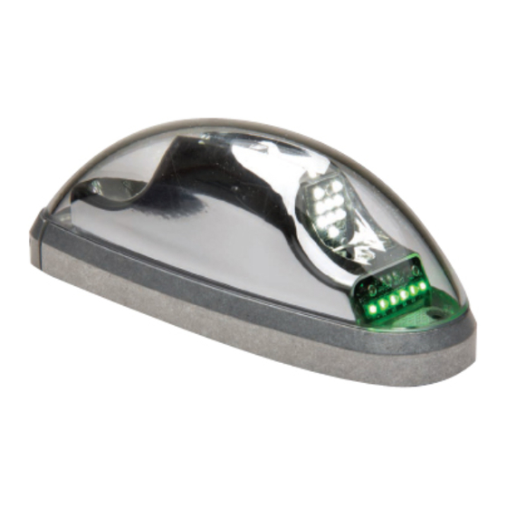
Aviation model(s) OR600C4R, OR600C4G
01-0771733-25
P/N
6.
Re-install the light assembly on to the baseplate and insure that all leads
are clear of any obstructions and secured as required. Note that proper
orientation is achieved with the drain hole down.
7.
Install lens in the reverse order as removal, return the lens retainer to its
installed location, re-insert #2 cap head screw and tighten firmly. Confirm
proper gasket fit.
8.
When necessary, waterproof the light base to aircraft. Apply single-part
Silicone (RTV) or equivalent around any open area where water could
get in. Do not cover the drain hole.
9.
Check all avionics systems for interference from this installation.
10.
A flight check should be performed by a properly certified pilot.
11.
If required, update aircraft records utilizing FAA Field Approval (Form
337) or equivalent.
5.65
1.78
20 AWG WIRE
20 AWG WIRE
58" LG. W/AMP
38" LG. W/AMP
61117-1 SOCKET
61117-1 SOCKET
Installation Guide/ICA:
01-0771733-26
,
Orion 600 Wingtip PTA
Suggested
.29
Mounting
Pattern
ENVELOPE OF
LIGHT ASS'Y
Ø1.00 THRU
4X TYPICAL
MOUNTING
HOLE FOR #6,
100° C'SINK
1.00
2.04
Advertisement

Related Manuals for Whelen Engineering Company WAT Orion 600 Series


Summary of Contents for Whelen Engineering Company WAT Orion 600 Series
- Page 1 Installation Guide/ICA: Phone: (860) 526-9504 Aviation model(s) OR600C4R, OR600C4G Internet: www.flyWAT.com 01-0771733-25 01-0771733-26 Sales/Service e-mail: info@flyWAT.com Orion 600 Wingtip PTA The conditions and tests required for TSO approval of this article are minimum performance standards. TSO-C30c TSO-C96a Those installing this article either on or within a specific type or class of aircraft must determine that TYPE I, II &...
- Page 2 QTY QTY ITEM PART NUMBER DESCRIPTION 0 1 - 0 7 7 1 7 3 3 - 2 5 OR600C4G, Wingtip PTA, 28V (Green) 0 1 - 0 7 7 1 7 3 3 - 2 6 OR600C4R, Wingtip PTA, 28V (Red) 0 6 - 1 7 2 0 6 6 - 2 0 0 BASEPLATE, 4-HOLE MODEL 71733 W/HELICOILS ASS'Y, 28V LED WINGTIP LIGHT GRN, CIRRUS 4 HOLE...
Need help?
Do you have a question about the WAT Orion 600 Series and is the answer not in the manual?
Questions and answers